2011 INFINITI QX56 torque
[x] Cancel search: torquePage 720 of 5598

REPLACEMENT OPERATIONSBRM-45
< REMOVAL AND INSTALLATION >
C
DE
F
G H
I
J
L
M A
B
BRM
N
O P
Rear Floor RearINFOID:0000000006248506
Work after rear panel and rear end crossmember are removed.
1. Rear side member 2. Rear end cross bracket
Unit: mm (in) : Vehicle front
: Welding method, the number of welding points, and the tightening torque apply to both side of the vehicle.
JSKIA1921GB
Revision: 2010 May2011 QX56
Page 745 of 5598
![INFINITI QX56 2011 Factory Service Manual
CCS-10
< SYSTEM DESCRIPTION >[ICC]
COMPONENT PARTS
Component Description
INFOID:0000000006224266
× : Applicable
13. Steering angle sensor
Refer to BRC-10, "
Component Parts
Location"
14. ADAS cont INFINITI QX56 2011 Factory Service Manual
CCS-10
< SYSTEM DESCRIPTION >[ICC]
COMPONENT PARTS
Component Description
INFOID:0000000006224266
× : Applicable
13. Steering angle sensor
Refer to BRC-10, "
Component Parts
Location"
14. ADAS cont](/manual-img/42/57033/w960_57033-744.png)
CCS-10
< SYSTEM DESCRIPTION >[ICC]
COMPONENT PARTS
Component Description
INFOID:0000000006224266
× : Applicable
13. Steering angle sensor
Refer to BRC-10, "
Component Parts
Location"
14. ADAS control unit
Refer to DAS-13, "
Component Parts
Location"
A. Back side of engine room (RH) B. Front bumper (center) C. Upper side of brake pedal
D. Under side of inst rument lower driver
panel
Component Function
Description
Vehicle-to-vehicle distance control mode
Conventional (fixed speed) cruise control mode Intelligent Brake Assist (IBA)
Brake Assist (with preview function)
ADAS control unit ×××× ADAS control unit calculates a target distance between vehicles
and a target speed, based on signals received from each sensor
and switch to transmit an engine torque command value to ECM
and a brake fluid pres sure control signal to ABS actuator and
electric unit (control unit) via CAN communication
ADAS control unit transmits buzzer output signal to combination
meter via CAN communication
ICC sensor ×××× ICC sensor detects light reflected from a vehicle ahead by irra-
diating laser forward and calculates a distance from the vehicle
ahead and a relative speed, based on the detected signal
ICC sensor transmits the presence/absence of vehicle ahead and the distance from the vehicle to ADAS control unit via ITS
communication
ECM ×××× ECM transmits the accelerator pedal position signal, ICC brake
switch signal, stop lamp switch signal, ICC steering switch sig-
nal, etc. to ADAS control unit via CAN communication
ECM controls the electric throttle control actuator based on the engine torque demand received from the ADAS control unit via
CAN communication
ABS actuator and electric unit
(control unit) ×××× ABS actuator and electric unit (control unit) transmits the vehicle
speed signal (wheel speed), stop lamp signal and VDC/TCS/
ABS system operation condition to ADAS control unit via CAN
communication
ABS actuator and electric unit (control unit) controls the brake, based on a brake fluid pressure control signal received from the
ADAS control unit via CAN communication
BCM ×BCM transmits the front wiper request signal to ADAS control unit
via CAN communication
TCM ××TCM transmits the signal related to A/T control to ADAS control
unit via CAN communication
Revision: 2010 May2011 QX56
Page 956 of 5598

CO-14
< REMOVAL AND INSTALLATION >
RADIATOR
to release built-up pressure. Carefully remove radiator cap by turning it all the way. Note that the reser-
voir tank cap side is also under pressure.
1. Remove front under cover with power tool. Refer to EXT-25, "
Exploded View".
2. Remove engine cover. Refer to EM-25, "
Exploded View".
3. Drain engine coolant from radiator. Refer to CO-8, "
Draining".
CAUTION:
Perform this step when the engine is cold.
Never spill engine coolant on drive belts.
4. Remove radiator hose (lower).
5. Remove fan shroud (lower). Refer to CO-13, "
Exploded View".
6. Move reservoir tank to the position without the hindrance for work.
7. Remove radiator core support cover. Refer to DLK-220, "
Exploded View".
8. Remove fan shroud (upper), refer to following.
a. Remove EVAP hose mounting bolts and move harness to aside.
b. Move air cleaner case to the position without the hindrance for work. Refer to EM-27, "
Exploded View".
NOTE:
The air cleaner case connector is not required to be disconnected.
9. Remove radiator grille. Refer to EXT-19, "
Exploded View".
10. Move condenser to the position without the hindranc e for work with the following procedures. Refer to HA-
38, "Exploded View".
Remove mounting bolts and disconnect A/C piping from radiator.
Remove air guide from radiator. Refer to EXT-12, "
Exploded View".
Remove radiator mounting bolts.
11. Remove radiator hose (upper).
12. Remove radiator as per the following: CAUTION:
Be careful not to damage radiator core.
Lift up and pull the radiator (1) forward, and then remove themounting rubber (lower) (3) from the radiator core support (2).
INSTALLATION
Note the following, and install in the reverse order of removal.
CAUTION:
Use genuine mounting bolts for th e cooling fan assembly and strictly observe the tightening torque.
(Breakage prevention for radiator)
NOTE:
Insert the radiator hose (1) all the way to the st opper (2) or by 33 mm (1.30 in) (hose without a stopper).
: Vehicle front
JPBIA3431ZZ
JPBIA4294GB
Revision: 2010 May2011 QX56
Page 1753 of 5598
HOOD
DLK-217
< REMOVAL AND INSTALLATION >
C
D E
F
G H
I
J
L
M A
B
DLK
N
O P
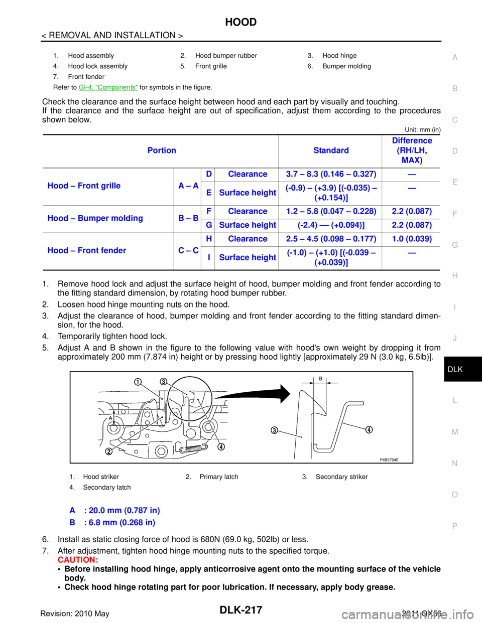
Check the clearance and the surface height betw een hood and each part by visually and touching.
If the clearance and the surface height are out of spec ification, adjust them according to the procedures
shown below.
Unit: mm (in)
1. Remove hood lock and adjust the surface height of hood, bumper molding and front fender according to
the fitting standard dimension, by rotating hood bumper rubber.
2. Loosen hood hinge mounting nuts on the hood.
3. Adjust the clearance of hood, bumper molding and fr ont fender according to the fitting standard dimen-
sion, for the hood.
4. Temporarily tighten hood lock.
5. Adjust A and B shown in the figure to the following value with hood's own weight by dropping it from approximately 200 mm (7.874 in) height or by pressi ng hood lightly [approximately 29 N (3.0 kg, 6.5lb)].
6. Install as static closing force of hood is 680N (69.0 kg, 502lb) or less.
7. After adjustment, tighten hood hinge mounting nuts to the specified torque. CAUTION:
Before installing hood hinge, apply anticorrosive agent onto th e mounting surface of the vehicle
body.
Check hood hinge rotating pa rt for poor lubrication. If necessary, apply body grease.
1. Hood assembly 2. Hood bumper rubber 3. Hood hinge
4. Hood lock assembly 5. Front grille 6. Bumper molding
7. Front fender
Refer to GI-4, "
Components" for symbols in the figure.
Portion Standard Difference
(RH/LH, MAX)
Hood – Front grille A – A D Clearance 3.7 – 8.3 (0.146 – 0.327) —
E Surface height (-0.9) – (+3.9) [(-0.035) –
(+0.154)] —
Hood – Bumper molding B – B F Clearance 1.2 – 5.8 (0.047 – 0.228) 2.2 (0.087)
G Surface height (-2.4) –– (+0.094)] 2.2 (0.087)
Hood – Front fender C – C H Clearance 2.5 – 4.5 (0.098 – 0.177) 1.0 (0.039)
I Surface height (-1.0) – (+1.0) [(-0.039 –
(+0.039)] —
1. Hood striker 2. Primary latch 3. Secondary striker
4. Secondary latch
A : 20.0 mm (0.787 in)
B : 6.8 mm (0.268 in)
PIIB5794E
Revision: 2010 May2011 QX56
Page 1762 of 5598
DLK-226
< REMOVAL AND INSTALLATION >
FRONT DOOR
4. Temporarily tighten door hinge mounting nuts on door side.
5. Loosen door hinge mounting bolts on body side.
6. Raise front door at rear end to adjust clearance of the front door according to the fitting standard dimen-
sion.
7. After adjustment tighten bolts and nuts to the specified torque. CAUTION:
After installation, apply touch-up paint (the bo dy color) onto the head of hinge mounting bolts
and nuts.
Check door hinge rotating part for poor lubrication. If necessary, apply body grease.
8. Install front fender. Refer to refer to DLK-222, "
FRONT FENDER : Removal and Installation".
DOOR STRIKER ADJUSTMENT
Adjust door striker so that it becomes parallel with door lock insertion direction.
DOOR STRIKER
DOOR STRIKER : Removal and InstallationINFOID:0000000006226077
REMOVAL
Remove TORX bolts, and then remove door striker.
INSTALLATION
Note the following items, and then install in the reverse order of removal.
CAUTION:
Check front door open/close, operation after installation.
After installation, be sure to perf orm the fitting adjustment. Refer to DLK-225, "
DOOR ASSEMBLY :
Adjustment".
DOOR HINGE
DOOR HINGE : Removal and InstallationINFOID:0000000006226078
REMOVAL
CAUTION:
Perform work with 2 workers, because of its heavy weight.
When removing and installing front door assembly, support door with a jack and shop cloth to pro-
tect door and body.
1. Remove front fender. Refer to DLK-222, "
FRONT FENDER : Removal and Installation".
2. Remove front door assembly. Refer to DLK-224, "
DOOR ASSEMBLY : Removal and Installation".
3. Remove front door hinge mounting bolts (body side), and then remove front door hinge.
INSTALLATION
Note the following items, and then install in the reverse order of removal.
CAUTION:
Apply anticorrosive agent onto the mounting surface.
Check front door open/close, lock/un lock operation after installation.
Check door hinge rotating pa rt for poor lubrication. If necessary, apply body grease.
After installation, perform th e fitting adjustment. Refer to DLK-225, "
DOOR ASSEMBLY : Adjust-
ment".
After installation, apply touch-up paint (the body color) onto the head of door hinge mounting nuts.
DOOR CHECK LINK
DOOR CHECK LINK : Re moval and InstallationINFOID:0000000006226079
REMOVAL
1. Fully close the front door window.
2. Remove front door finisher. Refer to INT-14, "
Removal and Installation".
3. Remove front door speaker mounting bolts.
4. Disconnect connector and remove front door speaker.
Revision: 2010 May2011 QX56
Page 1766 of 5598
DLK-230
< REMOVAL AND INSTALLATION >
REAR DOOR
1. Remove center pillar lower garnish. Refer to INT-22, "CENTER PILLAR LOWER GARNISH : Removal
and Installation".
2. Loosen door hinge mounting nuts on door side.
3. Adjust the surface height of rear door according to the fitting standard dimension.
4. Temporarily tighten door hinge mounting nuts on door side.
5. Loosen door hinge mounting nuts and bolts on body side.
6. Raise rear door at rear end to adjust clearance of rear door according to the fitting standard dimension.
7. After adjustment tighten bolts and nuts to the specified torque. CAUTION:
After installation, apply touch-up paint (the bo dy color) onto the head of hinge mounting bolts
and nuts.
Check door hinge rotating part for poor lubrication. If necessary, apply body grease.
8. Install center pillar lower garnish. Refer to INT-22, "
CENTER PILLAR LOWER GARNISH : Removal and
Installation".
DOOR STRIKER ADJUSTMENT
Adjust door striker so that it becomes parallel with door lock insertion direction.
DOOR STRIKER
DOOR STRIKER : Removal and InstallationINFOID:0000000006226083
REMOVAL
Remove TORX bolts, and then remove door striker.
INSTALLATION
Note the following items, and then install in the reverse order of removal.
CAUTION:
Check rear door open/c lose, after installation.
After installation, be sure to perf orm the fitting adjustment. Refer to DLK-229, "
DOOR ASSEMBLY :
Adjustment".
DOOR HINGE
DOOR HINGE : Removal and InstallationINFOID:0000000006226084
CAUTION:
Perform work with 2 workers, because of it’s heavy weight.
When removing and installing r ear door assembly, support door with a jack and shop cloth to pro-
tect door and body.
REMOVAL
1. Remove rear door assembly. Refer to DLK-228, "DOOR ASSEMBLY : Removal and Installation".
2. Remove center pillar lower garnish. Refer to INT-22, "
CENTER PILLAR LOWER GARNISH : Removal
and Installation".
3. Remove rear door hinge mounting bolts and nuts (body side), and then remove door hinge.
INSTALLATION
Note the following items, and then install in the reverse order of removal.
CAUTION:
Apply anticorrosive agent onto the mounting surface.
Check rear door open/close op eration after installation.
Check door hinge rotating pa rt for poor lubrication. If necessary, apply body grease.
When removing and inst alling rear door assembly, perform the fitting adjustment. Refer to DLK-229,
"DOOR ASSEMBLY : Adjustment".
After installing, apply the touch-up paint (the body color) onto the head of door hinge mounting nuts.
DOOR CHECK LINK
DOOR CHECK LINK : Removal and InstallationINFOID:0000000006226085
REMOVAL
Revision: 2010 May2011 QX56
Page 1803 of 5598
DLN-1
TRANSMISSION & DRIVELINE
CEF
G H
I
J
K L
M
SECTION DLN
A
B
DLN
N
O P
CONTENTS
DRIVELINE
TRANSFER: ATX90A
PRECAUTION ................ ...............................
6
PRECAUTIONS .............................................. .....6
Precaution for Supplemental Restraint System
(SRS) "AIR BAG" and "SEAT BELT PRE-TEN-
SIONER" ............................................................. ......
6
Precaution Necessary for Steering Wheel Rota-
tion after Battery Disconnect .....................................
6
Service Notice or Precautions for Transfer ...............7
PREPARATION ............................................8
PREPARATION .............................................. .....8
Special Service Tools .......................................... ......8
Commercial Service Tools ........................................8
SYSTEM DESCRIPTION .............................10
COMPONENT PARTS ................................... ....10
Component Parts Location .................................. ....10
Component Description ...........................................11
Transfer Control Unit ...............................................11
Transfer Control Actuator ........................................11
Transfer Hi-Lo Position Sensor ...............................12
Transfer Rotary Position Sensor .............................12
Transfer Lock Position Sensor ................................12
Transfer Fluid Temperature Sensor ........................12
STRUCTURE AND OPERATION .......................13
Sectional View ..................................................... ....13
Torque Split Mechanism .........................................13
SYSTEM .............................................................18
4WD SYSTEM ...........................................................18
4WD SYSTEM : System De scription ......................18
4WD SYSTEM : Fail-Safe ......................... ..............20
DIAGNOSIS SYSTEM (TRANSFER CON-
TROL UNIT) .................................................... ....
21
CONSULT-III Function ........................................ ....21
ECU DIAGNOSIS INFORMATION ..............24
TRANSFER CONTROL UNIT ...........................24
Reference Value .................................................. ....24
Fail-Safe ..................................................................28
DTC Inspection Priority Chart ..................................29
DTC Index ...............................................................29
WIRING DIAGRAM ......................................31
4WD SYSTEM .. ................................ .................31
Wiring Diagram .................................................... ....31
BASIC INSPECTION ...................................38
DIAGNOSIS AND REPAIR WORK FLOW .......38
Work Flow ............................................................ ....38
Diagnostic Work Sheet ............................................39
ADDITIONAL SERVICE WHEN REPLACING
TRANSFER CONTROL UNIT ...........................
41
Description ...............................................................41
Work Procedure .......................................................41
ADDITIONAL SERVICE WHEN REPLACING
TRANSFER ASSEMBLY ..................................
42
Description ...............................................................42
Work Procedure .......................................................42
TRANSFER LOCK POSITION SENSOR
LEARNING ....................................... .................
44
Description ........................................................... ....44
Work Procedure .......................................................44
TRANSFER ROTARY POSITION SENSOR
LEARNING ....................................... .................
46
Description ........................................................... ....46
Work Procedure .......................................................46
TRANSFER FLUID VISCOSITY LEARNING ....47
Description ...............................................................47
Revision: 2010 May2011 QX56
Page 1807 of 5598
DLN-5
CEF
G H
I
J
K L
M A
B
DLN
N
O P
Removal and Installation .....................................
..
156
SIDE OIL SEAL ................................................160
Exploded View .................................................... ..160
Removal and Installation .......................................160
UNIT REMOVAL AND INSTALLATION ....162
FRONT FINAL DRIVE ASSEMBLY ............... ..162
Exploded View .................................................... ..162
Removal and Installation .......................................162
UNIT DISASSEMBLY AND ASSEMBLY ..164
SIDE SHAFT ................................................... ..164
Exploded View .................................................... ..164
Disassembly ..........................................................165
Assembly ...............................................................166
Inspection ..............................................................166
DIFFERENTIAL ASSEMBLY ...........................167
Exploded View .................................................... ..167
Disassembly ..........................................................168
Assembly ...............................................................169
Adjustment ............................................................171
Inspection ..............................................................174
DRIVE PINION ..................................................176
Exploded View .................................................... ..176
Disassembly ..........................................................177
Assembly ...............................................................179
Adjustment ............................................................181
Inspection ..............................................................184
SERVICE DATA AND SPECIFICATIONS
(SDS) ......... ................................. ................
185
SERVICE DATA AND SPECIFICATIONS
(SDS) .............................................................. ..
185
General Specifications ........................................ ..185
Drive Gear Runout ................................................185
Preload Torque .....................................................185
Backlash ................................................................185
Companion Flange Runout ...................................185
REAR FINAL DRIVE: R230
PRECAUTION ................ ............................
186
PRECAUTIONS .............................................. ..186
Service Notice or Precautions for Rear Final Drive ..186
PREPARATION .........................................187
PREPARATION .............................................. ..187
Special Service Tool ........................................... ..187
Commercial Service Tool ......................................189
SYSTEM DESCRIPTION ...........................191
STRUCTURE AND OPERATION ...................191
Sectional View ..................................................... ..191
SYMPTOM DIAGNOSIS ............................192
NOISE, VIBRATION AND HARSHNESS
(NVH) TROUBLESHOOTING .........................
192
NVH Troubleshooting Chart ................................ ..192
PERIODIC MAINTENANCE ......................193
REAR DIFFERENTIAL GEAR OIL .................193
Inspection ............................................................ ..193
Draining .................................................................193
Refilling ..................................................................193
REMOVAL AND INSTALLATION .............194
FRONT OIL SEAL ...........................................194
Exploded View ..................................................... ..194
Removal and Installation .......................................194
SIDE OIL SEAL ...............................................199
Exploded View .......................................................199
Removal and Installation .......................................199
UNIT REMOVAL AND INSTALLATION ....201
REAR FINAL DRIVE .......................................201
Exploded View ..................................................... ..201
Removal and Installation .......................................201
UNIT DISASSEMBLY AND ASSEMBLY ..203
DIFFERENTIAL ASSEMBLY ..........................203
Exploded View ..................................................... ..203
Disassembly ..........................................................204
Assembly ...............................................................206
Adjustment .............................................................210
Inspection ..............................................................215
DRIVE PINION ................................................216
Exploded View .......................................................216
Disassembly ..........................................................217
Assembly ...............................................................218
Adjustment .............................................................220
Inspection ..............................................................220
SERVICE DATA AND SPECIFICATIONS
(SDS) ............... ...........................................
222
SERVICE DATA AND SPECIFICATIONS
(SDS) ...............................................................
222
General Specification .......................................... ..222
Drive Gear Runout .................................................222
Side Gear Clearance .............................................222
Preload Torque ......................................................222
Backlash ................................................................222
Companion Flange Runout ....................................222
Revision: 2010 May2011 QX56