2011 INFINITI QX56 chg
[x] Cancel search: chgPage 1579 of 5598

DIAGNOSIS SYSTEM (BCM)DLK-43
< SYSTEM DESCRIPTION >
C
DE
F
G H
I
J
L
M A
B
DLK
N
O P
*: OFF is displayed when brake pedal is depressed while brake switch power supply is OFF.
ACTIVE TEST
S/L LOCK-IPDM Indicates [On/Off] condition of steering lock unit (LOCK)
S/L UNLK-IPDM Indicates [On/Off] condition of steering lock unit (UNLOCK)
S/L RELAY-REQ Indicates [On/Off] condition of steering lock relay
VEH SPEED 1 Display the vehicle speed signal received from combination meter by numerical value [Km/h]
VEH SPEED 2 Display the vehicle spee d signal received from ABS or VDC or TCM by numerical value [Km/h]
DOOR STAT-DR Indicates [LOCK/READY/UNLK] condition of unlock sensor
DOOR STAT-AS Indicates [LOCK/READY/UNLK] condition of passenger side door status
ID OK FLAG Indicates [Set/Reset] condition of key ID
PRMT ENG STRT Indicates [Set/Reset] condition of engine start possibility
PRMT RKE STRT NOTE:
This item is displayed, but cannot be monitored
TRNK/HAT MNTR NOTE:
This item is displayed, but cannot be monitored
RKE-LOCK Indicates [On/Off] condition of LOCK signal from Intelligent Key
RKE-UNLOCK Indicates [On/Off] condition of UNLOCK signal from Intelligent Key
RKE-TR/BD NOTE:
This item is displayed, but cannot be monitored
RKE-PANIC Indicates [On/Off] condition of PANIC button of Intelligent Key
RKE-MODE CHG Indicates [On/Off] condition of MODE CHANGE signal from Intelligent Key
RKE OPE COUN1 When remote keyless entry receiver receives the signal transmitted while operating on Intelli-
gent Key, the numerical value start changing
RKE OPE COUN2 NOTE:
This item is displayed, but cannot be monitored
Monitor Item Condition
Test item Description
BATTERY SAVER This test is able to check interior room lamp operation
On: Operate
Off: Non-operation
OUTSIDE BUZZER This test is able to check Intelligent Key warning buzzer operation
On: Operate
Off: Non-operation
INSIDE BUZZER This test is able to check warning chime in combination meter operation
Take Out: Take away warning chime sounds when CONSULT-III screen is touched
Key: Key warning chime sounds when CONSULT-III screen is touched
Knob: OFF position warning chime sounds when CONSULT-III screen is touched
Off: Non-operation
INDICATOR This test is able to check warning lamp operation
KEY ON: “KEY” Warning lamp illuminates when CONSULT-III screen is touched
KEY IND: “KEY” Warning lamp blinks when CONSULT-III screen is touched
Off: Non-operation
INT LAMP This test is able to check interior room lamp operation
On: Operate
Off: Non-operation
Revision: 2010 May2011 QX56
Page 2046 of 5598
![INFINITI QX56 2011 Factory Service Manual
EC-22
< SYSTEM DESCRIPTION >[VK56VD]
COMPONENT PARTS
Battery Current Sensor (With Battery Temperature Sensor)
INFOID:0000000006217663
OUTLINE
The power generation voltage variable control enables fu INFINITI QX56 2011 Factory Service Manual
EC-22
< SYSTEM DESCRIPTION >[VK56VD]
COMPONENT PARTS
Battery Current Sensor (With Battery Temperature Sensor)
INFOID:0000000006217663
OUTLINE
The power generation voltage variable control enables fu](/manual-img/42/57033/w960_57033-2045.png)
EC-22
< SYSTEM DESCRIPTION >[VK56VD]
COMPONENT PARTS
Battery Current Sensor (With Battery Temperature Sensor)
INFOID:0000000006217663
OUTLINE
The power generation voltage variable control enables fuel con-
sumption to be decreased by reducing the engine load which is
caused by the power generation of the generator.
Based on sensor signals, ECM judges whether or not the power
generation voltage variable control is performed. When performing
the power generation voltage variable control, ECM calculates the
target power generation voltage based on the sensor signal. And
ECM sends the calculated value as the power generation command
value to IPDM E/R. For the details of the power generation voltage
variable control, refer to CHG-7, "
POWER GENERATION VOLTAGE
VARIABLE CONTROL SYSTEM : System Description".
CAUTION:
Never connect the electrical component or the groun d wire directly to the battery terminal. The con-
nection causes the malfunction of th e power generation voltage variable control, and then the battery
discharge may occur.
BATTERY CURRENT SENSOR
The battery current sensor is installed to the battery cable at the negative terminal. The sensor measures the
charging/discharging current of the battery.
BATTERY TEMPERATURE SENSOR
Battery temperature sensor is int egrated in battery current sensor.
The sensor measures ambient temperature around the battery.
The electrical resistance of the t hermistor decreases as temperature
increases.
*: These data are reference values and are measured between ECM terminals.
Camshaft Position SensorINFOID:0000000006217664
The camshaft position (CMP) sensor senses the protrusion of the
signal plate installed to the camshaft (INT) front end to identify a par-
ticular cylinder. The camshaft position sensor senses the piston posi-
tion.
The sensor consists of a permanent magnet and Hall IC.
When engine is running, the high and low parts of the teeth cause
the gap with the sensor to change.
The changing gap causes the magnetic field near the sensor to
change.
Due to the changing magnetic field, the voltage from the sensor
changes.
When the crankshaft position sens or system becomes inoperative,
the camshaft position sensor provides various controls of engine parts instead, utilizing timing of cylinder iden-
tification signals.
JPBIA3262ZZ
Temperature [ °C ( °F)] Voltage* (V) Resistance (k Ω)
25 (77) 3.333 1.9 - 2.1
90 (194) 0.969 0.222 - 0.258
SEF012P
JMBIA0064ZZ
Revision: 2010 May2011 QX56
Page 2060 of 5598
![INFINITI QX56 2011 Factory Service Manual
EC-36
< SYSTEM DESCRIPTION >[VK56VD]
SYSTEM
DIRECT INJECTION GASOLINE SYSTEM
DIRECT INJECTION GASOLINE
SYSTEM : System DiagramINFOID:0000000006217699
DIRECT INJECTION GASOLINE SY STEM : System Descr INFINITI QX56 2011 Factory Service Manual
EC-36
< SYSTEM DESCRIPTION >[VK56VD]
SYSTEM
DIRECT INJECTION GASOLINE SYSTEM
DIRECT INJECTION GASOLINE
SYSTEM : System DiagramINFOID:0000000006217699
DIRECT INJECTION GASOLINE SY STEM : System Descr](/manual-img/42/57033/w960_57033-2059.png)
EC-36
< SYSTEM DESCRIPTION >[VK56VD]
SYSTEM
DIRECT INJECTION GASOLINE SYSTEM
DIRECT INJECTION GASOLINE
SYSTEM : System DiagramINFOID:0000000006217699
DIRECT INJECTION GASOLINE SY STEM : System DescriptionINFOID:0000000006217700
INPUT/OUTPUT SIGNAL CHART
Function Reference
Fuel injection control EC-36, "
DIRECT INJECTION GASOLINE
SYSTEM : System De-
scription"
Fuel pressure control EC-39, "FUEL PRESSURE CONTROL : System Description"
Cooling fan controlEC-41, "COOLING FAN CONTROL : System Description"
Electric ignition controlEC-42, "ELECTRIC IGNITION SYSTEM : System Description"
Intake valve timing controlEC-43, "INTAKE VALVE TIMING CONTROL : System Description"
VVEL (Variable Valve Event & Lift) EC-44, "VVEL SYSTEM : System Description"
Evaporative emissionEC-45, "EVAPORATIVE EMISSION SYSTEM : System Descrip-
tion"
Air conditioning cut controlEC-47, "AIR CONDITIONING CUT CONT
ROL : System Descrip-
tion"
ASCD (Auto speed control device) EC-48, "AUTOMATIC SPEED CONTROL DEVICE (ASCD) : Sys-
tem Description"
Power generation voltage variable controlCHG-7, "POWER GENERATION VOLTAGE VARIABLE CON-
TROL SYSTEM : System Description"
JSBIA0471GB
Revision: 2010 May2011 QX56
Page 2551 of 5598
![INFINITI QX56 2011 Factory Service Manual
ENGINE CONTROL SYSTEM SYMPTOMSEC-527
< SYMPTOM DIAGNOSIS > [VK56VD]
C
D
E
F
G H
I
J
K L
M A
EC
NP
O
Air Air duct
55555 5 EM-28
Air cleaner
EM-27
Air leakage from air duct
(Mass air flow sensor — el INFINITI QX56 2011 Factory Service Manual
ENGINE CONTROL SYSTEM SYMPTOMSEC-527
< SYMPTOM DIAGNOSIS > [VK56VD]
C
D
E
F
G H
I
J
K L
M A
EC
NP
O
Air Air duct
55555 5 EM-28
Air cleaner
EM-27
Air leakage from air duct
(Mass air flow sensor — el](/manual-img/42/57033/w960_57033-2550.png)
ENGINE CONTROL SYSTEM SYMPTOMSEC-527
< SYMPTOM DIAGNOSIS > [VK56VD]
C
D
E
F
G H
I
J
K L
M A
EC
NP
O
Air Air duct
55555 5 EM-28
Air cleaner
EM-27
Air leakage from air duct
(Mass air flow sensor — electric
throttle control actuator)
5555 EM-28
Electric throttle control actuator
EC-460
Air leakage from intake manifold/
Collector/GasketEM-30
Cranking Battery
111111
11
PG-161
Generator circuit
CHG-13
Starter circuit 3STR-11
Signal plate 6EM-106
PNP signal 4EC-383
Engine Cylinder head
55555 55 5 EM-92
Cylinder head gasket 4 3
Cylinder block
66666 66 6 4
EM-115
Piston
Piston ring
Connecting rod
Bearing
Crankshaft
Va l v e
mecha-
nism Timing chain
55555 55 5 EM-72
Camshaft
EM-77
Intake valve timing controlEM-61
Intake valve
3EM-92
Exhaust valve
Exhaust Exhaust manifold/Tube/Muffler/ Gasket 55555 55 5 EM-42
EX-6Three way catalystSYMPTOM
Reference
page
HARD/NO START/RESTART (EXCP. HA)
ENGINE STALL
HESITATION/SURGING/FLAT SPOT
SPARK KNOCK/DETONATION
LACK OF POWER/POOR ACCELERATION
HIGH IDLE/LOW IDLE
ROUGH IDLE/HUNTING
IDLING VIBRATION
SLOW/NO RETURN TO IDLE
OVERHEATS/WATER TEMPERATURE HIGH
EXCESSIVE FUEL CONSUMPTION
EXCESSIVE OIL CONSUMPTION
BATTERY DEAD (UNDER CHARGE)
Warranty symptom code AA AB AC AD AE AF AG AH AJ AK AL AM HA
Revision: 2010 May2011 QX56
Page 2602 of 5598

EM-40
< REMOVAL AND INSTALLATION >
EXHAUST MANIFOLD AND THREE WAY CATALYST
EXHAUST MANIFOLD AND THREE WAY CATALYST
Exploded ViewINFOID:0000000006289550
Removal and InstallationINFOID:0000000006289551
REMOVAL
WARNING:
Perform the work when the exhaust and cooling system have cooled sufficiently.
1. Drain engine coolant from radiator. Refer to CO-8, "
Draining".
CAUTION:
Perform this step when the engine is cold.
Never spill engine coolant on drive belt.
2. Remove reservoir tank. Refer to CO-13, "
Exploded View".
3. Remove drive belt. Refer to EM-20, "
Removal and Installation".
4. Remove power steering oil pump. Refer to ST-48, "
Exploded View".
5. Remove radiator. Refer to CO-13, "
Exploded View".
6. Remove front under cover. Refer to EXT-25, "
Exploded View".
7. Remove front wheels and tires. Refer to WT-64, "
Exploded View".
8. Remove A/C compressor. Refer to HA-30, "
Exploded View".
9. Remove alternator and alternator bracket. Refer to CHG-25, "
Exploded View".
10. Remove exhaust front tube (bank 1 and bank 2). Refer to EX-5, "
Exploded View".
1. Air fuel ratio sensor 1 (bank 2) 2. Exhaust manifold cover (bank 2) 3. Exhaust manifold and three way cat-
alyst (bank 2)
4. Gasket 5. Exhaust manifold and three way cat-
alyst (bank 1)6. Exhaust manifold cover (bank 1)
7. Air fuel ratio sensor 1 (bank 1)
Refer to GI-4, "
Components" for symbols in the figure.
JSBIA0389GB
Revision: 2010 May2011 QX56
Page 2624 of 5598

EM-62
< REMOVAL AND INSTALLATION >
TIMING CHAIN
Removal and Installation
INFOID:0000000006289566
REMOVAL
1. Release fuel pressure. Refer to EC-153, "Work Procedure".
2. Drain engine coolant from radiator. Refer to CO-8, "
Draining".
3. Remove fan shroud (lower). Refer to CO-13, "
Exploded View".
4. Remove fan bracket. Refer to CO-16, "
Exploded View".
5. Remove drive belt auto-tensioner. Refer to EM-26, "
Exploded View".
6. Remove oil level gauge and oil level gauge guide. Refer to EM-57, "
Exploded View".
7. Move power steering oil pump to the posit ion without the hindrance for work. Refer to ST-48, "
Exploded
View".
8. Remove alternator, alternator bracket and alternator stay. Refer to CHG-25, "
Exploded View".
9. Move power steering reservoir tank to the position without the hindrance for work, and then remove Res- ervoir tank bracket. Refer to ST-54, "
Exploded View".
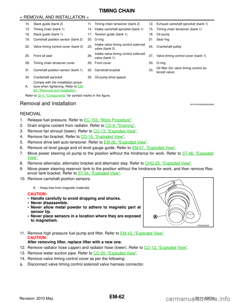
10. Remove camshaft position sensors.
CAUTION:
Handle carefully to avoid dropping and shocks.
Never disassemble.
Never allow metal powder to adhere to magnetic part atsensor tip.
Never place sensors in a lo cation where they are exposed
to magnetism.
11. Remove high pressure fuel pump and lifter. Refer to EM-43, "
Exploded View".
CAUTION:
After removing lifter, replace lifter with a new one.
12. Remove radiator hose (upper) and radiator hose (lower). Refer to CO-13, "
Exploded View".
13. Remove water suction pipe. Refer to CO-20, "
Exploded View".
14. Remove valve timing control cover as per the following:
a. Disconnect valve timing control solenoid valve harness connector.
10. Slack guide (bank 2) 11. Timing chain tensioner (bank 2) 12. Exhaust camshaft sprocket (bank 1)
13. Timing chain (bank 1) 14. Intake camshaft sprocket (bank 1) 15. Timing chain tensioner (bank 1)
16. Slack guide (bank 1) 17. Tension guide (bank 1) 18. Oil pump
19. Camshaft position sensor (bank 2) 20. O-ring 21. Seal ring
22. Valve timing control cover (bank 2) 23. Intake valve timing control solenoid
valve (bank 2)24. Crankshaft pulley
25. Front oil seal 26. Intake valve timing control solenoid
valve (bank 1)27. Valve timing control cover (bank 1)
28. Timing chain tensioner cover 29. Front cover 30. O-ring
31. Camshaft position sensor (bank 1) 32. Camshaft bracket 33. Oil filter (for valve timing control so-
lenoid valve)
34. Crankshaft sprocket 35. Oil pump drive spacer
A. Comply with the installation proce-
dure when tightening. Refer to
EM-
62, "Removal and Installation".
Refer to GI-4, "
Components" for symbol marks in the figure.
A : Keep free from magnetic materials
JPBIA0454ZZ
Revision: 2010 May2011 QX56
Page 2663 of 5598

ENGINE ASSEMBLYEM-101
< UNIT REMOVAL AND INSTALLATION >
C
DE
F
G H
I
J
K L
M A
EM
NP
O
5. Remove A/T assembly. Refer to
TM-205, "2WD : Exploded View" (2WD models) or TM-208, "4WD :
Exploded View" (4WD models).
6. Remove steering gear assembly. Refer to ST-41, "
Exploded View".
7. Remove front final drive assembly. Refer to DLN-162, "
Exploded View".
8. Remove exhaust manifold. Refer to EM-40, "
Exploded View".
9. Remove alternator. Refer to CHG-25, "
Exploded View".
Engine Room LH
1. Remove air cleaner and air duct. Refer to EM-27, "Exploded View".
2. Remove A/C compressor. Refer to HA-30, "
Exploded View".
3. Disconnect fuel feed hose and EVAP hose. Refer to EM-43, "
Exploded View".
CAUTION:
Fit plugs onto disconnected hoses to prevent fuel leakage.
Engine Room RH
1. Remove power steering oil pump and reservoir tank. Refer to ST-48, "Exploded View".
2. Disconnect heater hose at heater core side, and fit a plug onto hose end to prevent engine coolant leak-
age.
3. Disconnect ground cable.
4. Disconnect all clips and connectors of the engine harness from vehicle side.
Removal Work
1. Install alternator bracket. Refer to CHG-25, "Exploded View".
Temporarily tighten mounting bolts.
2. Remove intake manifold. Refer to EM-30, "
Exploded View".
3. Remove starter motor. Refer to STR-17, "
Exploded View".
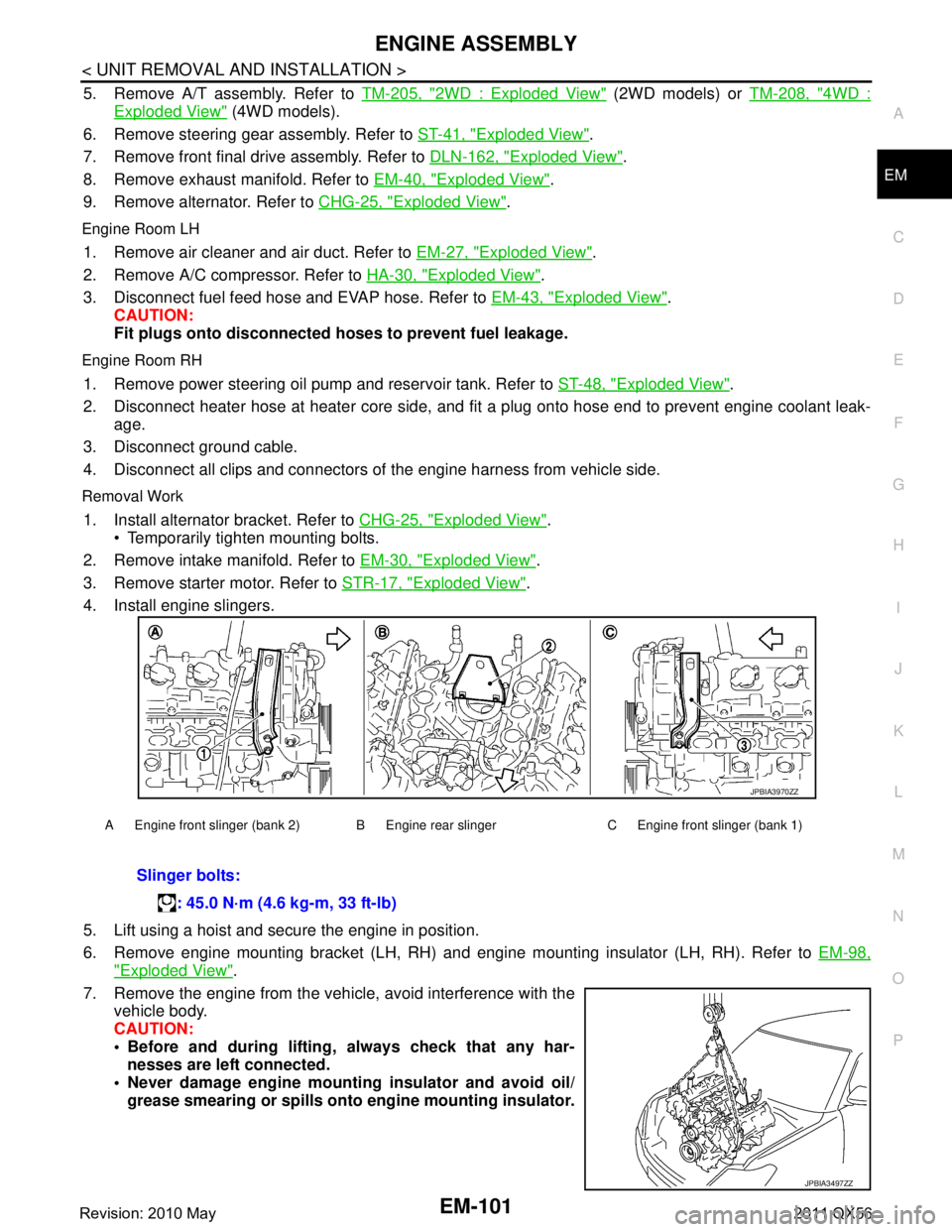
4. Install engine slingers.
5. Lift using a hoist and secure the engine in position.
6. Remove engine mounting bracket (LH, RH) and engine mounting insulator (LH, RH). Refer to EM-98,
"Exploded View".
7. Remove the engine from the vehi cle, avoid interference with the
vehicle body.
CAUTION:
Before and during lifting, always check that any har-
nesses are left connected.
Never damage engine mounti ng insulator and avoid oil/
grease smearing or spills onto engine mounting insulator.
A Engine front slinger (bank 2) B Engine rear slinger C Engine front slinger (bank 1)
Slinger bolts:
: 45.0 N·m (4.6 kg-m, 33 ft-lb)
JPBIA3970ZZ
JPBIA3497ZZ
Revision: 2010 May2011 QX56
Page 3666 of 5598

OIL PUMPLU-13
< REMOVAL AND INSTALLATION >
C
DE
F
G H
I
J
K L
M A
LU
NP
O
OIL PUMP
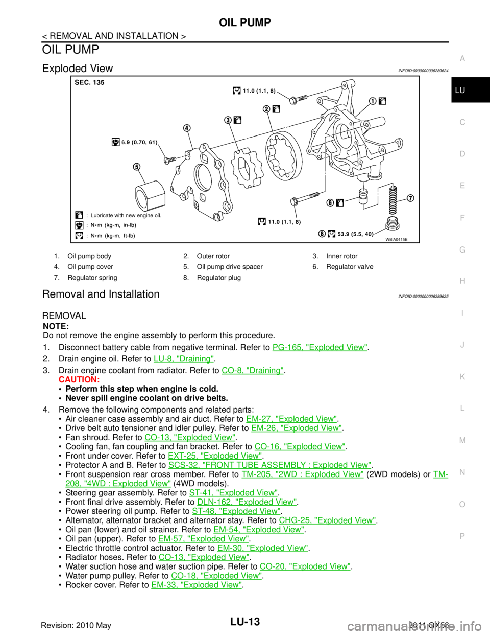
Exploded ViewINFOID:0000000006289624
Removal and InstallationINFOID:0000000006289625
REMOVAL
NOTE:
Do not remove the engine assembly to perform this procedure.
1. Disconnect battery cable from
negative terminal. Refer to PG-165, "
Exploded View".
2. Drain engine oil. Refer to LU-8, "
Draining".
3. Drain engine coolant from radiator. Refer to CO-8, "
Draining".
CAUTION:
Perform this step when engine is cold.
Never spill engine coolant on drive belts.
4. Remove the following components and related parts: Air cleaner case assembly and air duct. Refer to EM-27, "
Exploded View".
Drive belt auto tensioner and idler pulley. Refer to EM-26, "
Exploded View".
Fan shroud. Refer to CO-13, "
Exploded View".
Cooling fan, fan coupling and fan bracket. Refer to CO-16, "
Exploded View".
Front under cover. Refer to EXT-25, "
Exploded View".
Protector A and B. Refer to SCS-32, "
FRONT TUBE ASSEMBLY : Exploded View".
Front suspension rear cross member. Refer to TM-205, "
2WD : Exploded View" (2WD models) or TM-
208, "4WD : Exploded View" (4WD models).
Steering gear assembly. Refer to ST-41, "
Exploded View".
Front final drive assembly. Refer to DLN-162, "
Exploded View".
Power steering oil pump. Refer to ST-48, "
Exploded View".
Alternator, alternator bracket and alternator stay. Refer to CHG-25, "
Exploded View".
Oil pan (lower) and oil strainer. Refer to EM-54, "
Exploded View".
Oil pan (upper). Refer to EM-57, "
Exploded View".
Electric throttle control actuator. Refer to EM-30, "
Exploded View".
Radiator hoses. Refer to CO-13, "
Exploded View".
Water suction hose and water suction pipe. Refer to CO-20, "
Exploded View".
Water pump pulley. Refer to CO-18, "
Exploded View".
Rocker cover. Refer to EM-33, "
Exploded View".
WBIA0415E
1. Oil pump body 2. Outer rotor 3. Inner rotor
4. Oil pump cover 5. Oil pump drive spacer 6. Regulator valve
7. Regulator spring 8. Regulator plug
Revision: 2010 May2011 QX56