2011 INFINITI QX56 door
[x] Cancel search: doorPage 3053 of 5598
GW-24
< REMOVAL AND INSTALLATION >
REAR DOOR GLASS
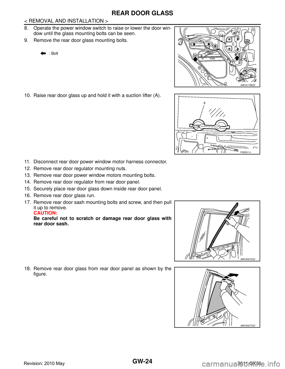
8. Operate the power window switch to raise or lower the door win-dow until the glass mounting bolts can be seen.
9. Remove the rear door glass mounting bolts.
10. Raise rear door glass up and hold it with a suction lifter (A).
11. Disconnect rear door power window motor harness connector.
12. Remove rear door regulator mounting nuts.
13. Remove rear door power window motors mounting bolts.
14. Remove rear door regulator from rear door panel.
15. Securely place rear door glass down inside rear door panel.
16. Remove rear door glass run.
17. Remove rear door sash mounting bolts and screw, and then pull it up to remove.
CAUTION:
Be careful not to scratch or damage rear door glass with
rear door sash.
18. Remove rear door glass from rear door panel as shown by the figure.
: Bolt
JMKIA1789ZZ
PIIB3511J
JMKIA5272ZZ
JMKIA5273ZZ
Revision: 2010 May2011 QX56
Page 3054 of 5598
REAR DOOR GLASSGW-25
< REMOVAL AND INSTALLATION >
C
DE
F
G H
I
J
L
M A
B
GW
N
O P
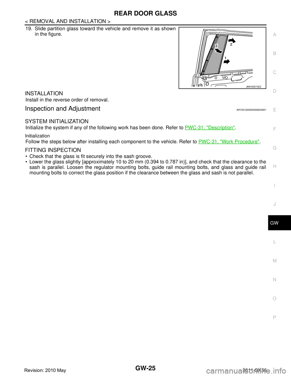
19. Slide partition glass toward the vehicle and remove it as shown in the figure.
INSTALLATION
Install in the reverse order of removal.
Inspection and AdjustmentINFOID:0000000006220831
SYSTEM INITIALIZATION
Initialize the system if any of t he following work has been done. Refer to PWC-31, "Description".
Initialization
Follow the steps below after installing each component to the vehicle. Refer to PWC-31, "Work Procedure".
FITTING INSPECTION
Check that the glass is fit securely into the sash groove.
Lower the glass slightly [approximately 10 to 20 mm (0.394 to 0.787 in)], and check that the clearance to the
sash is parallel. Loosen the regulator mounting bolts, guide rail mounting bolts, and glass and guide rail
mounting bolts to correct the glass position if the clearance between the glass and sash is not parallel.
JMKIA5274ZZ
Revision: 2010 May2011 QX56
Page 3055 of 5598
GW-26
< REMOVAL AND INSTALLATION >
REAR REGULATOR
REAR REGULATOR
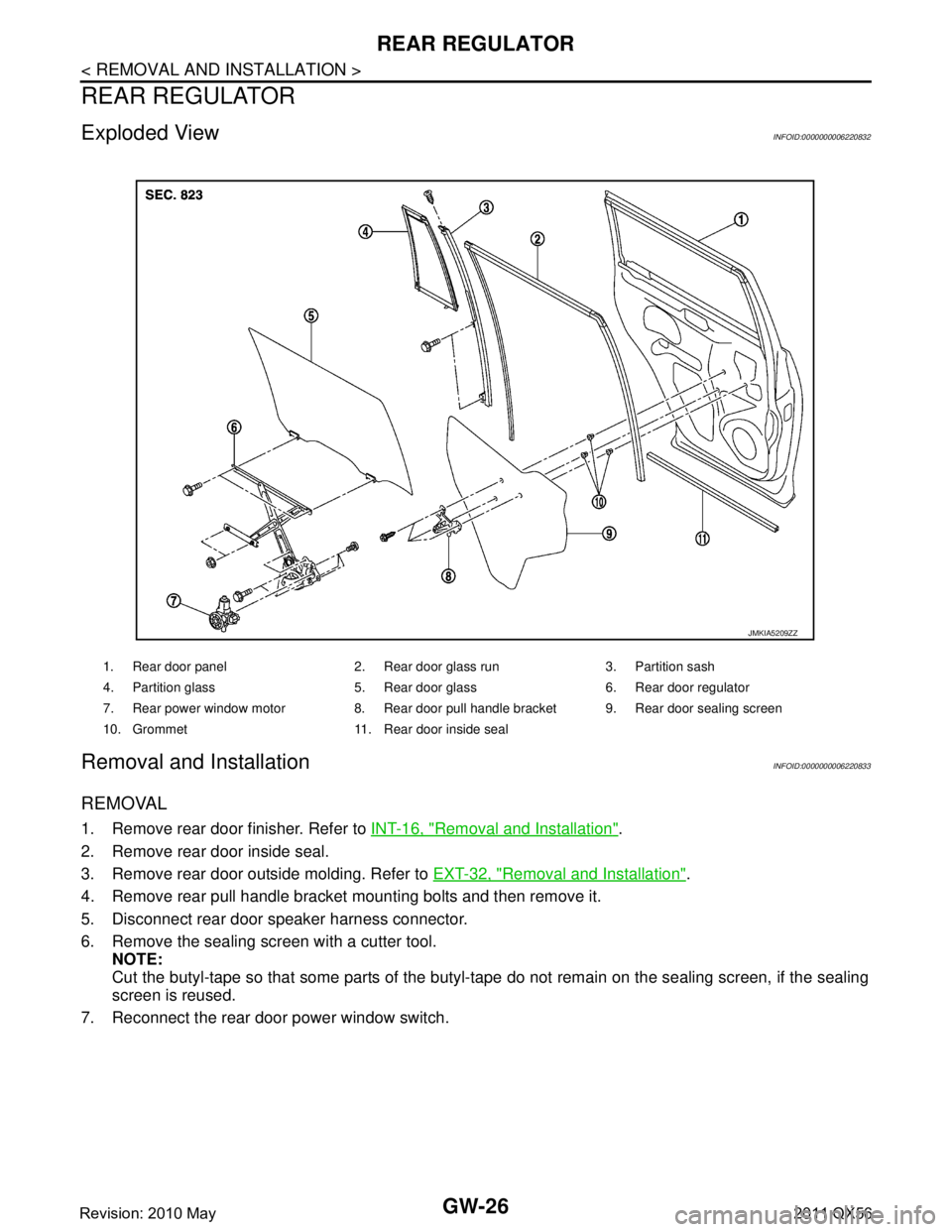
Exploded ViewINFOID:0000000006220832
Removal and InstallationINFOID:0000000006220833
REMOVAL
1. Remove rear door finisher. Refer to INT-16, "Removal and Installation".
2. Remove rear door inside seal.
3. Remove rear door outside molding. Refer to EXT-32, "
Removal and Installation".
4. Remove rear pull handle bracket mounting bolts and then remove it.
5. Disconnect rear door speaker harness connector.
6. Remove the sealing screen with a cutter tool. NOTE:
Cut the butyl-tape so that some parts of the butyl-t ape do not remain on the sealing screen, if the sealing
screen is reused.
7. Reconnect the rear door power window switch.
1. Rear door panel 2. Rear door glass run 3. Partition sash
4. Partition glass 5. Rear door glass 6. Rear door regulator
7. Rear power window motor 8. Rear door pull handle bracket 9. Rear door sealing screen
10. Grommet 11. Rear door inside seal
JMKIA5209ZZ
Revision: 2010 May2011 QX56
Page 3056 of 5598
REAR REGULATORGW-27
< REMOVAL AND INSTALLATION >
C
DE
F
G H
I
J
L
M A
B
GW
N
O P
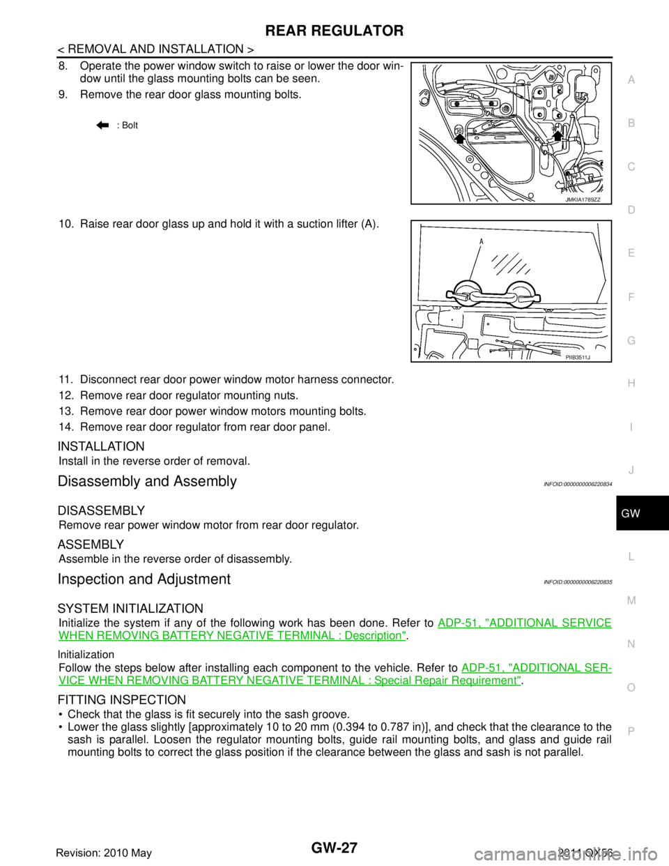
8. Operate the power window switch to raise or lower the door win- dow until the glass mounting bolts can be seen.
9. Remove the rear door glass mounting bolts.
10. Raise rear door glass up and hold it with a suction lifter (A).
11. Disconnect rear door power window motor harness connector.
12. Remove rear door regulator mounting nuts.
13. Remove rear door power window motors mounting bolts.
14. Remove rear door regulator from rear door panel.
INSTALLATION
Install in the reverse order of removal.
Disassembly and AssemblyINFOID:0000000006220834
DISASSEMBLY
Remove rear power window motor from rear door regulator.
ASSEMBLY
Assemble in the reverse order of disassembly.
Inspection and AdjustmentINFOID:0000000006220835
SYSTEM INITIALIZATION
Initialize the system if any of t he following work has been done. Refer to ADP-51, "ADDITIONAL SERVICE
WHEN REMOVING BATTERY NEGATIVE TERMINAL : Description".
Initialization
Follow the steps below after installing each component to the vehicle. Refer to ADP-51, "ADDITIONAL SER-
VICE WHEN REMOVING BATTERY NEGATIVE TERMINAL : Special Repair Requirement".
FITTING INSPECTION
Check that the glass is fit securely into the sash groove.
Lower the glass slightly [approximately 10 to 20 mm (0.394 to 0.787 in)], and check that the clearance to the
sash is parallel. Loosen the regulator mounting bolts, guide rail mounting bolts, and glass and guide rail
mounting bolts to correct the glass position if the clearance between the glass and sash is not parallel.
: Bolt
JMKIA1789ZZ
PIIB3511J
Revision: 2010 May2011 QX56
Page 3075 of 5598
REFRIGERANTHA-19
< BASIC INSPECTION >
C
DE
F
G H
J
K L
M A
B
HA
N
O P
Never look directly into UV lamp light source.
NOTE:
For continuous operating time of UV lamp, fo llow the manufacturer operating instructions.
Illuminate piping joints from different angles us ing UV lamp and check that there is no leakage.
Use a mirror in area that is difficult to see to check refrigerant leakage.
Refrigerant leakage from evaporator can be detected by soaking cotton swab or a similar material with
drain hose water and illuminating it using UV lamp.
Dust, dirt, and packing materials adhesive used for condenser, evaporator, and other locations may flu- oresce. Be careful not to misidentify leakage.
5. Repair or replace parts where refrigerant leak age occurs and wipe off fluorescent leak detection dye.
NOTE:
Completely wipe off fluorescent leak detection dy e from gaps between parts, screw threads, and others
using a cotton swab or similar materials.
6. Use a UV lamp to check that no fluorescent leak detection dye remains after finishing work. WARNING:
Never look directly into UV lamp light source.
NOTE:
For continuous operating time of UV lamp, fo llow the manufacturer operating instructions.
Dust, dirt, and packing materials adhesive used for condenser, evaporator, and other locations may flu-
oresce. Be careful not to misidentify leakage.
CHECK REFRIGERANT LEAKAGE USIN G ELECTRICAL LEAK DETECTOR
WARNING:
Never check refrigerant leakage while the engine is running.
CAUTION:
Be careful of the following items so that in accurate checks or misidentifications are avoided.
Never allow refrigerant vapor, shop chemical vapors, cigarette smoke, or others around the vehicle.
Always check refrigerant leakage in a low air flow environment so that refrigerant may not disperse
when leakage occurs.
1. Stop the engine.
2. Connect recovery/recycling/recharging equipment or manifold gauge set to A/C service valve.
3. Check that A/C refrigerant pressure is 345 kPa (3.52 kg/cm
2, 50 psi) or more when temperature is 16 °C
(61 °F) or more. When pressure is lower than the spec ified value, recycle refrigerant completely and fill
refrigerant to the specified level.
NOTE:
Leakages may not be detected if A/C refri gerant pressure is 345 kPa (3.52 kg/cm
2, 50 psi) or less when
temperature is less than 16 °C (61 °F).
4. Clean area where refrigerant leakage check is per formed, and check refrigerant leakage along all sur-
faces of pipe connections and A/C system com ponents using electrical leak detector probe.
CAUTION:
Continue checking when a leakage is found. Always continue and complete checking along all
pipe connections and A/C system co mponents for additional leakage.
When a leakage is detected, clean leakage area using compressed air and check again.
When checking leakage of cooling unit inside, al ways clean inside of drain hose so that the
probe surface may not be exposed to water or dirt.
NOTE:
Always check leakage starting from high-pressure side and continue to low-pressure side.
When checking leakage of cooling unit inside, operate blower fan motor for 15 minutes or more at the maximum fan speed while the engine is stopped, and then insert electrical leak detector probe into drain
hose and hold for 10 minutes or more.
When disconnecting shut-off valve that is connected to A/C service valve, always evacuate remaining
refrigerant so that misidentification can be avoided.
5. Repair or replace parts where refrigerant leak age is detected. (Leakage is detected but leakage area is
unknown. GO TO 6.)
6. Start the engine and set A/C control in the following conditions. A/C switch ON
Air flow: VENT (ventilation)
Intake door position: Recirculation
Revision: 2010 May2011 QX56
Page 3078 of 5598
HA-22
< BASIC INSPECTION >
LUBRICANT
LUBRICANT
DescriptionINFOID:0000000006276153
MAINTENANCE OF LUBRICANT LEVEL
The compressor lubricant is circulating in the system together with the refrigerant. It is necessary to fill com-
pressor with lubricant when replacing A/C system pa rts or when a large amount of refrigerant leakage is
detected. It is important to always maintain lubricant level within the specified level. Otherwise, the following
conditions may occur.
Insufficient lubricant amount: Stuck compressor
Excessive lubricant amount: Insufficient cooling (caused by insufficient heat exchange)
InspectionINFOID:0000000006276154
If a compressor is malfunctioning (internal noise, insufficient cooling), check the compressor oil.
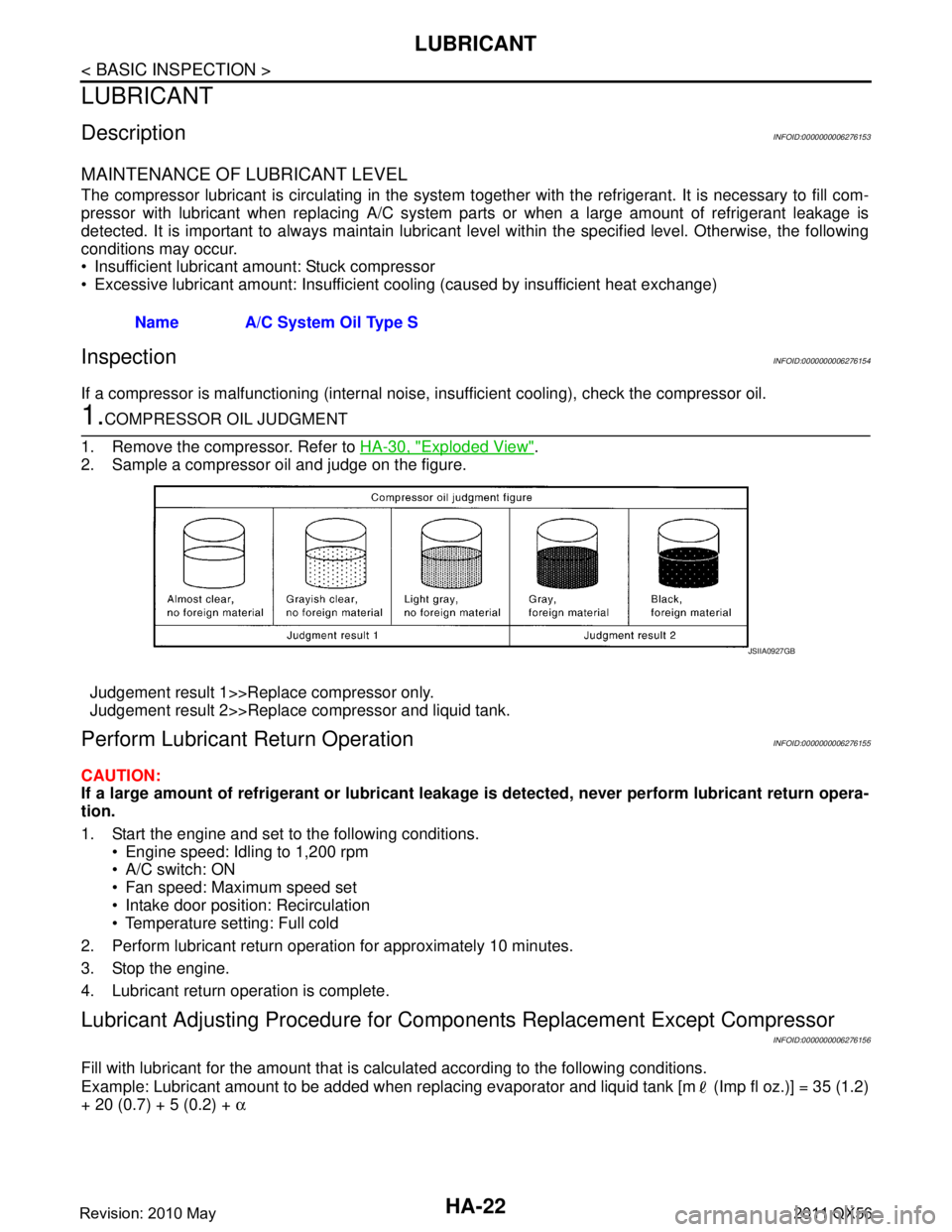
1.COMPRESSOR OIL JUDGMENT
1. Remove the compressor. Refer to HA-30, "
Exploded View".
2. Sample a compressor oil and judge on the figure.
Judgement result 1>>Replace compressor only.
Judgement result 2>>Replace compressor and liquid tank.
Perform Lubricant Return OperationINFOID:0000000006276155
CAUTION:
If a large amount of refrigerant or lubricant leakag e is detected, never perform lubricant return opera-
tion.
1. Start the engine and set to the following conditions.
Engine speed: Idling to 1,200 rpm
A/C switch: ON
Fan speed: Maximum speed set
Intake door position: Recirculation
Temperature setting: Full cold
2. Perform lubricant return operation for approximately 10 minutes.
3. Stop the engine.
4. Lubricant return operation is complete.
Lubricant Adjusting Procedure for Comp onents Replacement Except Compressor
INFOID:0000000006276156
Fill with lubricant for the amount that is calculated according to the following conditions.
Example: Lubricant amount to be added when replacing evapor ator and liquid tank [m (Imp fl oz.)] = 35 (1.2)
+ 20 (0.7) + 5 (0.2) + α
Name A/C System Oil Type S
JSIIA0927GB
Revision: 2010 May2011 QX56
Page 3081 of 5598
PERFORMANCE TESTHA-25
< BASIC INSPECTION >
C
DE
F
G H
J
K L
M A
B
HA
N
O P
PERFORMANCE TEST
InspectionINFOID:0000000006276158
INSPECTION PROCEDURE
1. Connect recovery/recycling/recharging equipment (for HFC-134a) or manifold gauge.
2. Start the engine, and set to the following condition.
Test condition
3. Maintain test condition until A/C system becomes stable. (Approximately 10 minutes)
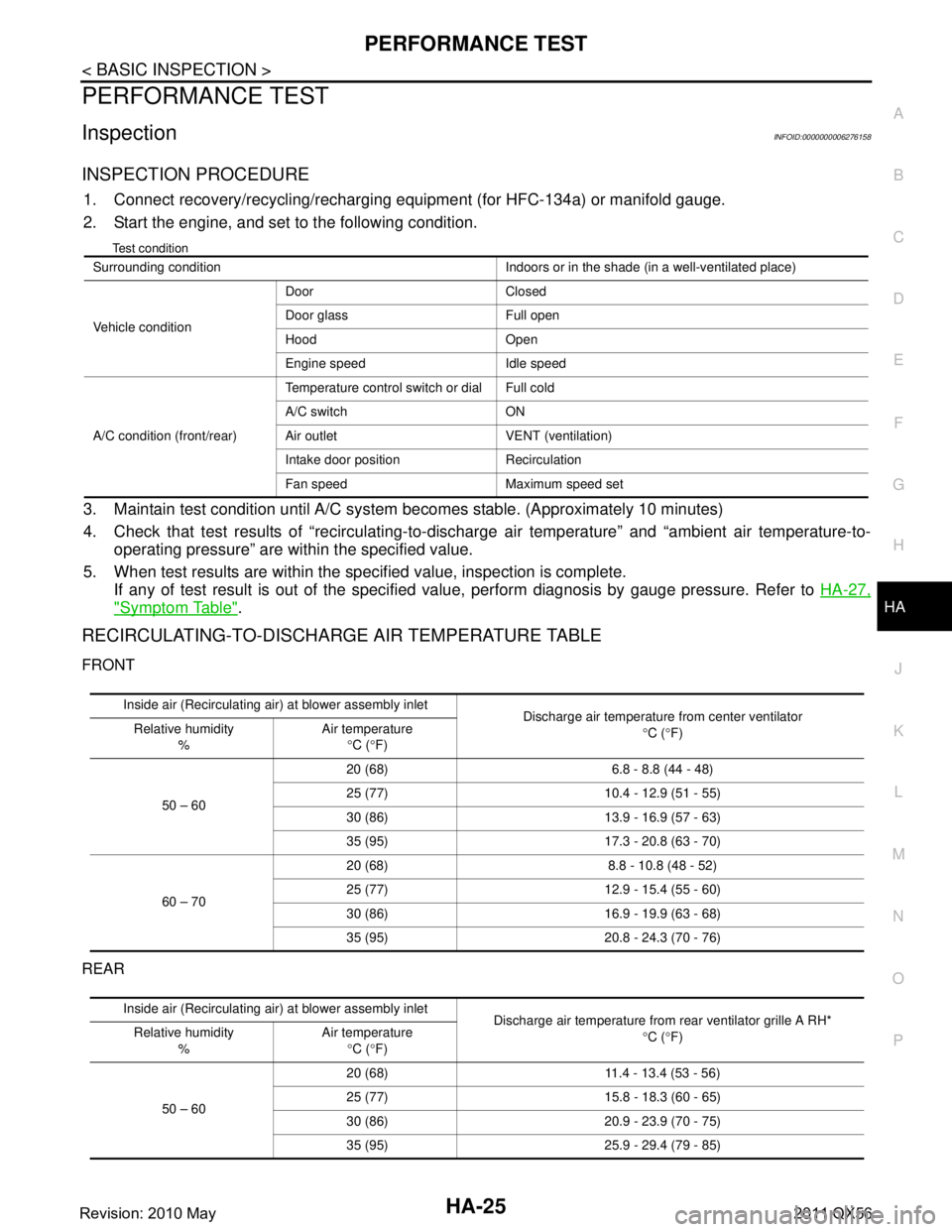
4. Check that test results of “recirculating-to-disc harge air temperature” and “ambient air temperature-to-
operating pressure” are within the specified value.
5. When test results are within the specified value, inspection is complete. If any of test result is out of the specified value, perform diagnosis by gauge pressure. Refer to HA-27,
"Symptom Table".
RECIRCULATING-TO-DISCHARGE AIR TEMPERATURE TABLE
FRONT
REAR
Surrounding condition Indoors or in the shade (in a well-ventilated place)
Vehicle conditionDoor Closed
Door glass Full open
Hood Open
Engine speed Idle speed
A/C condition (front/rear) Temperature control switch or dial Full cold
A/C switch ON
Air outlet VENT (ventilation)
Intake door position Recirculation
Fan speed Maximum speed set
Inside air (Recirculating air) at blower assembly inlet
Discharge air temperature from center ventilator
°C ( °F)
Relative humidity
% Air temperature
°C ( °F)
50 – 60 20 (68) 6.8 - 8.8 (44 - 48)
25 (77) 10.4 -
12.9 (51 - 55)
30 (86) 13.9 - 16.9 (57 - 63)
35 (95) 17.3 - 20.8 (63 - 70)
60 – 70 20 (68) 8.8 - 10.8 (48 - 52)
25 (77) 12.9 -
15.4 (55 - 60)
30 (86) 16.9 - 19.9 (63 - 68)
35 (95) 20.8 - 24.3 (70 - 76)
Inside air (Recirculating air) at blower assembly inlet
Discharge air temperature from rear ventilator grille A RH*
°C ( °F)
Relative humidity
% Air temperature
°C ( °F)
50 – 60 20 (68) 11.4 -
13.4 (53 - 56)
25 (77) 15.8 - 18.3 (60 - 65)
30 (86) 20.9 - 23.9 (70 - 75)
35 (95) 25.9 - 29.4 (79 - 85)
Revision: 2010 May2011 QX56
Page 3098 of 5598
HA-42
< REMOVAL AND INSTALLATION >
A/C UNIT ASSEMBLY
HEATER & COOLING UNIT ASSEMBLY
HEATER & COOLING UNIT ASSEMBLY : Removal and InstallationINFOID:0000000006276183
CAUTION:
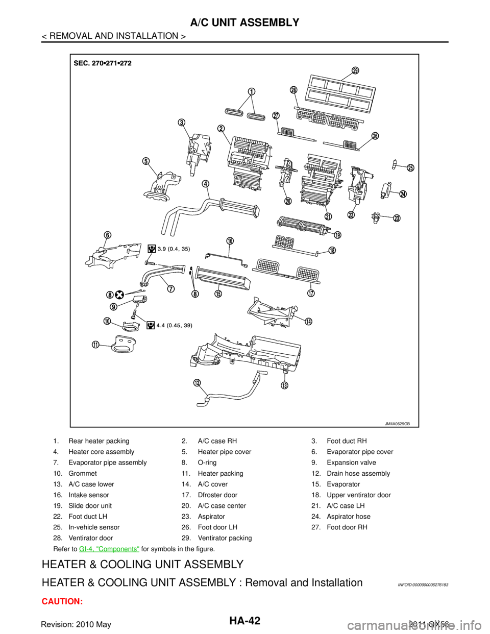
1. Rear heater packing 2. A/C case RH 3. Foot duct RH
4. Heater core assembly 5. Heater pipe cover 6. Evaporator pipe cover
7. Evaporator pipe assembly 8. O-ring 9. Expansion valve
10. Grommet 11. Heater packing 12. Drain hose assembly
13. A/C case lower 14. A/C cover 15. Evaporator
16. Intake sensor 17. Dfroster door 18. Upper ventirator door
19. Slide door unit 20. A/C case center 21. A/C case LH
22. Foot duct LH 23. Aspirator 24. Aspirator hose
25. In-vehicle sensor 26. Foot door LH 27. Foot door RH
28. Ventirator door 29. Ventirator packing
Refer to GI-4, "
Components" for symbols in the figure.
JMIIA0629GB
Revision: 2010 May2011 QX56