Page 5018 of 5598
POWER STEERING FLUIDST-31
< PERIODIC MAINTENANCE >
C
DE
F
H I
J
K L
M A
B
ST
N
O P
3. Repeat step 2 above several times at approximately 3 seconds intervals. CAUTION:
Never hold the steering wheel in a locked positio n for more than 10 seconds. (There is the possi-
bility that oil pump may be damaged.)
4. Check fluid for bubbles and while contamination.
5. Stop engine if bubbles and white contamination do not drain out. Perform step 2 and 3 above after waiting
until bubbles and white contamination drain out.
6. Stop the engine, and then check fluid level.
Revision: 2010 May2011 QX56
Page 5019 of 5598

ST-32
< PERIODIC MAINTENANCE >
STEERING WHEEL
STEERING WHEEL
InspectionINFOID:0000000006225598
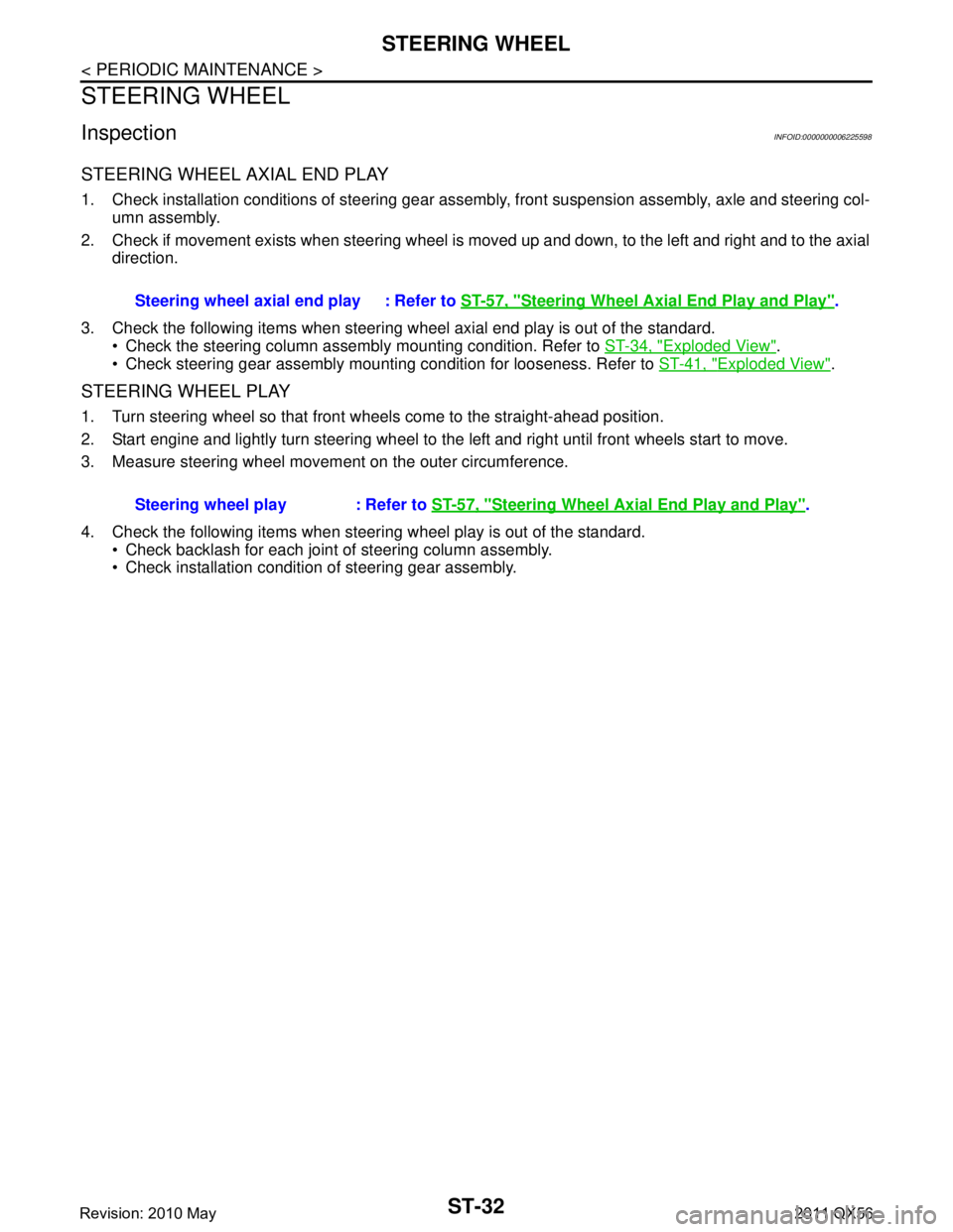
STEERING WHEEL AXIAL END PLAY
1. Check installation conditions of steering gear assembly, front suspension assembly, axle and steering col-
umn assembly.
2. Check if movement exists when steering wheel is moved up and down, to the left and right and to the axial direction.
3. Check the following items when steering w heel axial end play is out of the standard.
Check the steering column assembly mounting condition. Refer to ST-34, "
Exploded View".
Check steering gear assembly mounting condition for looseness. Refer to ST-41, "
Exploded View".
STEERING WHEEL PLAY
1. Turn steering wheel so that front wheels come to the straight-ahead position.
2. Start engine and lightly turn steering wheel to the left and right until front wheels start to move.
3. Measure steering wheel movement on the outer circumference.
4. Check the following items when steeri ng wheel play is out of the standard.
Check backlash for each joint of steering column assembly.
Check installation condition of steering gear assembly. Steering wheel axial end play : Refer to
ST-57, "
Steering Wheel Axial End Play and Play".
Steering wheel play : Refer to ST-57, "
Steering Wheel Axial End Play and Play".
Revision: 2010 May2011 QX56
Page 5020 of 5598

STEERING WHEELST-33
< REMOVAL AND INSTALLATION >
C
DE
F
H I
J
K L
M A
B
ST
N
O P
REMOVAL AND INSTALLATION
STEERING WHEEL
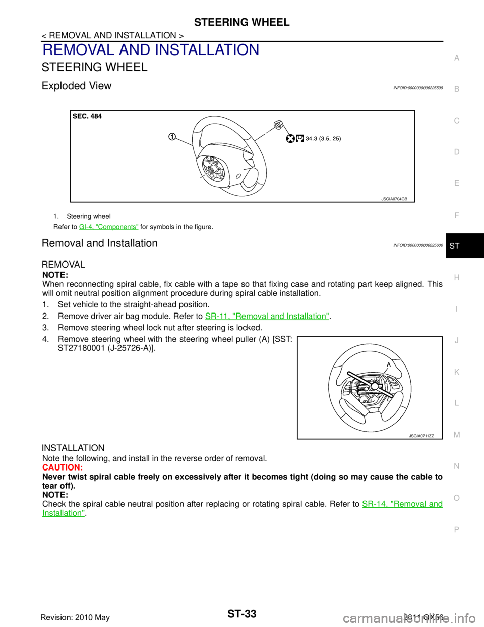
Exploded ViewINFOID:0000000006225599
Removal and InstallationINFOID:0000000006225600
REMOVAL
NOTE:
When reconnecting spiral cable, fix cable with a tape so that fixing case and rotating part keep aligned. This
will omit neutral position alignment procedure during spiral cable installation.
1. Set vehicle to the straight-ahead position.
2. Remove driver air bag module. Refer to SR-11, "
Removal and Installation".
3. Remove steering wheel lock nut after steering is locked.
4. Remove steering wheel with the steering wheel puller (A) [SST: ST27180001 (J-25726-A)].
INSTALLATION
Note the following, and install in the reverse order of removal.
CAUTION:
Never twist spiral cable freely on excessively after it becomes tight (doing so may cause the cable to
tear off).
NOTE:
Check the spiral cable neutral position after r eplacing or rotating spiral cable. Refer to SR-14, "
Removal and
Installation".
1. Steering wheel
Refer to GI-4, "
Components" for symbols in the figure.
JSGIA0704GB
JSGIA0711ZZ
Revision: 2010 May2011 QX56
Page 5021 of 5598

ST-34
< REMOVAL AND INSTALLATION >
STEERING COLUMN
STEERING COLUMN
Exploded ViewINFOID:0000000006225601
Removal and InstallationINFOID:0000000006225602
REMOVAL
CAUTION:
Never give axial impact to steering column assembly during removal.
Never move steering gear assembly when removing steering column assembly.
Never rotate the steering shaft when removing steering column assembly.
1. Set the vehicle to the straight-ahead position.
2. Place the tilt to the highest level. Place the telescopic to the longest level.
3. Remove driver air bag module. Refer to SR-11, "
Removal and Installation".
4. Remove steering wheel. Refer to ST-33, "
Removal and Installation".
5. Remove instrument lower panel LH. Refer to IP-14, "
Removal and Installation".
6. Remove the steering column cover. Refer to IP-14, "
Removal and Installation".
7. Remove spiral cable. Refer to SR-14, "
Removal and Installation".
8. Remove combination switch. Refer to BCS-82, "
Removal and Installation".
9. Disconnect each switch harness connectors installed to steering column assembly.
10. Remove the upper joint mounting bolt and separate the joint from upper joint.
11. Remove steering column assembly.
1. Bracket 2. Steering column mounting bracket 3. Upper joint
4. Telescopic motor 5. Tilt motor 6. Steering column assembly
Refer to GI-4, "
Components" for symbols in the figure.
JPGIA0066GB
Revision: 2010 May2011 QX56
Page 5023 of 5598
ST-36
< REMOVAL AND INSTALLATION >
STEERING COLUMN
Install the bracket and steering column housing so that the clear-ance (A) is within the specified range as described below. Replace
steering column assembly if out side the standard.
INSPECTION AFTER INSTALLATION
Check each part of steering column assembly for damage or other malfunctions. Replace if necessary.
Check the steering wheel play, neutral position steeri ng wheel, steering wheel turning force, and front wheel
turning angle. Refer to ST-32, "
Inspection".
Check tilt and telescopic mechanism operating range tilt operating
range (T), telescopic operating range (L) as shown in the figure.
Adjust neutral position of steering angle sensor. Refer to BRC-64,
"Work Procedure".
A : Refer to
ST-57, "
Steering Column Mounting Di-
mensions".
JSGIA0795ZZ
T : Refer to ST-57, "Steering Column Operating
Range".
L : Refer to ST-57, "
Steering Column Operating
Range".
JSGIA0798ZZ
Revision: 2010 May2011 QX56
Page 5024 of 5598

STEERING SHAFTST-37
< REMOVAL AND INSTALLATION >
C
DE
F
H I
J
K L
M A
B
ST
N
O P
STEERING SHAFT
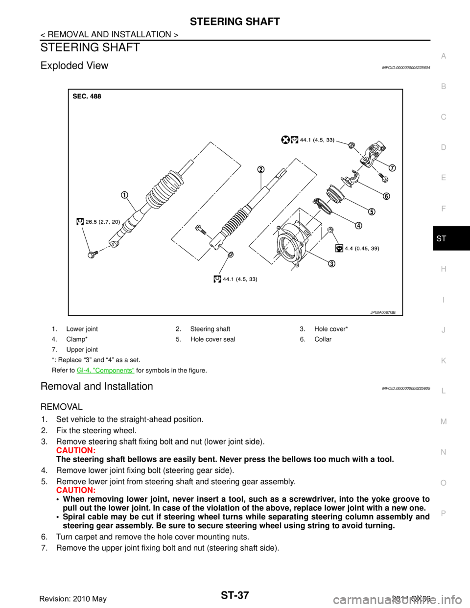
Exploded ViewINFOID:0000000006225604
Removal and InstallationINFOID:0000000006225605
REMOVAL
1. Set vehicle to the straight-ahead position.
2. Fix the steering wheel.
3. Remove steering shaft fixing bolt and nut (lower joint side). CAUTION:
The steering shaft bellows are easily bent. N ever press the bellows too much with a tool.
4. Remove lower joint fixing bolt (steering gear side).
5. Remove lower joint from steering shaft and steering gear assembly. CAUTION:
When removing lower joint, n ever insert a tool, such as a screw driver, into the yoke groove to
pull out the lower joint. In case of the violation of the above, replace lower joint with a new one.
Spiral cable may be cut if steering wheel tu rns while separating steering column assembly and
steering gear assembly. Be sure to secure st eering wheel using string to avoid turning.
6. Turn carpet and remove the hole cover mounting nuts.
7. Remove the upper joint fixing bolt and nut (steering shaft side).
1. Lower joint 2. Steering shaft 3. Hole cover*
4. Clamp* 5. Hole cover seal 6. Collar
7. Upper joint
*: Replace “3” and “4” as a set.
Refer to GI-4, "
Components" for symbols in the figure.
JPGIA0067GB
Revision: 2010 May2011 QX56
Page 5025 of 5598

ST-38
< REMOVAL AND INSTALLATION >
STEERING SHAFT
8. Remove the steering shaft from upper joint by sliding the steer-ing shaft (A: sliding range).
9. Remove the steering shaft and hole cover.
10. Remove collar, hole cover seal, and hole cover assembly. CAUTION:
Never damage hole cover seal.
11. Perform inspection after removal. Refer to ST-39, "
Inspection".
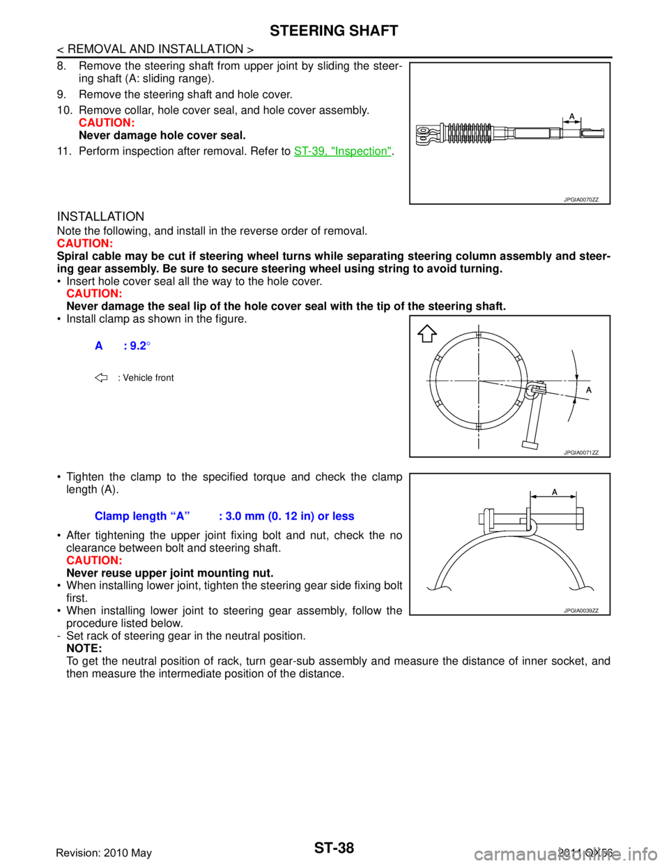
INSTALLATION
Note the following, and install in the reverse order of removal.
CAUTION:
Spiral cable may be cut if steering wheel turns while separating steering column assembly and steer-
ing gear assembly. Be sure to secure steer ing wheel using string to avoid turning.
Insert hole cover seal all the way to the hole cover. CAUTION:
Never damage the seal lip of the hole cover seal with the tip of the steering shaft.
Install clamp as shown in the figure.
Tighten the clamp to the spec ified torque and check the clamp
length (A).
After tightening the upper joint fixing bolt and nut, check the no clearance between bolt and steering shaft.
CAUTION:
Never reuse upper joint mounting nut.
When installing lower joint, tighten the steering gear side fixing bolt
first.
When installing lower joint to steering gear assembly, follow the procedure listed below.
- Set rack of steering gear in the neutral position. NOTE:
To get the neutral position of rack, turn gear-sub as sembly and measure the distance of inner socket, and
then measure the intermediate position of the distance.
JPGIA0070ZZ
A: 9.2 °
: Vehicle front
JPGIA0071ZZ
Clamp length “A” : 3.0 mm (0. 12 in) or less
JPGIA0039ZZ
Revision: 2010 May2011 QX56
Page 5027 of 5598
ST-40
< REMOVAL AND INSTALLATION >
STEERING SHAFT
Rotate the steering shaft to check runout of the steering shaft atthe runout measuring point ( ) by using dial indicator and V-block.
Check each part of steering shaft for damage and other malfunc- tions. Replace if there is a malfunction.
INSPECTION AFTER INSTALLATION
Check dust boot bellows (deformation, such as dent s). Manually rework the bellows, as necessary.
Check if steering wheel turns smoothly when it is tur ned several times fully to the end of the left and right.
Check the steering wheel play, neutral position steeri ng wheel, steering wheel turning force, and front wheel
turning angle. Refer to ST-32, "
Inspection".
Adjust neutral position of steering angle sensor. Refer to BRC-64, "
Work Procedure".
Runout : Refer to
ST-58, "
Steering Shaft Sliding
Range".
A : 120 mm (4.72 in)
B : 240 mm (9.45 in)
JPGIA0075ZZ
Revision: 2010 May2011 QX56