2011 INFINITI QX56 ground
[x] Cancel search: groundPage 1539 of 5598
DLK-3
C
DE
F
G H
I
J
L
M A
B
DLK
N
O P
Diagnosis Procedure ...........................................
....
98
B2423 AUTOMATIC BACK DOOR MOTOR
OPERATION TIME .............................................
99
DTC Logic ........................................................... ....99
Diagnosis Procedure ...............................................99
B2424 CLOSURE CONDITION ........................100
DTC Logic ........................................................... ..100
Diagnosis Procedure .............................................100
Component Inspection ..........................................101
B2425 AUTOMATIC BACK DOOR CONTROL
UNIT ..................................................................
103
DTC Logic ........................................................... ..103
Diagnosis Procedure .............................................103
B2621 INSIDE ANTENNA ................................104
DTC Logic ........................................................... ..104
Diagnosis Procedure .............................................104
B2622 INSIDE ANTENNA ................................106
DTC Logic ........................................................... ..106
Diagnosis Procedure .............................................106
B2623 INSIDE ANTENNA ................................108
DTC Logic ........................................................... ..108
Diagnosis Procedure .............................................108
B2626 OUTSIDE ANTENNA ............................110
DTC Logic ........................................................... ..110
Diagnosis Procedure .............................................110
B2627 OUTSIDE ANTENNA ............................112
DTC Logic ........................................................... ..112
Diagnosis Procedure .............................................112
B2628 OUTSIDE ANTENNA ............................114
DTC Logic ........................................................... ..114
Diagnosis Procedure .............................................114
POWER SUPPLY AND GROUND CIRCUIT ....116
AUTOMATIC BACK DOOR CONTROL UNIT ...... ..116
AUTOMATIC BACK DOOR CONTROL UNIT : Di-
agnosis Procedure ................................................
116
DOOR SWITCH ................................................117
Component Function Check .............................. ..117
Diagnosis Procedure .............................................117
Component Inspection ..........................................119
BACK DOOR SWITCH .....................................120
Component Function Check .............................. ..120
Diagnosis Procedure .............................................120
Component Inspection ..........................................121
DOOR LOCK AND UNLOCK SWITCH ............122
DRIVER SIDE ........................................................ ..122
DRIVER SIDE : Component Function Check ......122
DRIVER SIDE : Diagnosis Procedure ...................122
PASSENGER SIDE ..................................................122
PASSENGER SIDE :
Component Function Check .............................. ..
122
PASSENGER SIDE : Diagnosis Procedure ..........122
DOOR LOCK ACTUATOR ..............................123
DRIVER SIDE ......................................................... ..123
DRIVER SIDE : Component Function Check ......123
DRIVER SIDE : Diagnosis Procedure ...................123
PASSENGER SIDE ..................................................124
PASSENGER SIDE :
Component Function Check .............................. ..
124
PASSENGER SIDE : Diagnosis Procedure ..........124
REAR LH ................................................................ ..125
REAR LH : Component Function Check ..............125
REAR LH : Diagnosis Procedure ...........................125
REAR RH ............................................................... ..126
REAR RH : Component Function Check .............126
REAR RH : Diagnosis Procedure ..........................126
FUEL LID LOCK ACTUATOR ........................128
Component Function Check ................................128
Diagnosis Procedure .............................................128
UNLOCK SENSOR .........................................130
Component Function Check ................................130
Diagnosis Procedure .............................................130
Component Inspection ...........................................131
DOOR KEY CYLINDER SWITCH ...................132
Component Function Check ..................................132
Diagnosis Procedure .............................................132
Component Inspection ...........................................133
REMOTE KEYLESS ENTRY RECEIVER .......134
Component Function Check ................................134
Diagnosis Procedure .............................................134
DOOR REQUEST SWITCH ............................137
Component Function Check ................................137
Diagnosis Procedure .............................................137
Component Inspection ...........................................138
BACK DOOR REQUEST SWITCH .................139
Component Function Check ................................139
Diagnosis Procedure .............................................139
Component Inspection ...........................................140
BACK DOOR OPENER SWITCH ...................141
Component Function Check ................................141
Diagnosis Procedure .............................................141
Component Inspection ...........................................142
INTELLIGENT KEY WARNING BUZZER .......143
Component Function Check ................................143
Diagnosis Procedure .............................................143
Component Inspection ...........................................144
INTELLIGENT KEY .........................................145
Revision: 2010 May2011 QX56
Page 1540 of 5598

DLK-4
Component Function Check ................................145
Diagnosis Procedure .............................................145
COMBINATION METER BUZZER ..................146
Component Function Check .............................. ..146
Diagnosis Procedure .............................................146
INFORMATION DISPLAY ...............................147
Component Function Check .............................. ..147
Diagnosis Procedure .............................................147
KEY WARNING LAMP ....................................148
Component Function Check .............................. ..148
Diagnosis Procedure .............................................148
HAZARD FUNCTION .......................................149
Component Function Check .............................. ..149
Diagnosis Procedure .............................................149
AUTOMATIC BACK DOOR CLOSE SWITCH .150
Component Function Check .............................. ..150
Diagnosis Procedure .............................................150
Component Inspection ...........................................151
AUTOMATIC BACK DOOR MAIN SWITCH ...152
Component Function Check .............................. ..152
Diagnosis Procedure .............................................152
Component Inspection ...........................................153
AUTOMATIC BACK DOOR SWITCH .............154
Component Function Check .............................. ..154
Diagnosis Procedure .............................................154
Component Inspection ...........................................155
HALF LATCH SWITCH ...................................156
Component Function Check ................................ ..156
Diagnosis Procedure .............................................156
Component Inspection ...........................................157
TOUCH SENSOR ............................................158
RH ........................................................................... ..158
RH : Component Function Check ........................158
RH : Diagnosis Procedure .....................................158
RH : Component Inspection ..................................159
LH ........................................................................... ..159
LH : Component Function Check .........................159
LH : Diagnosis Procedure ......................................159
LH : Component Inspection ...................................160
BACK DOOR CLOSURE MOTOR ..................162
Diagnosis Procedure ........................................... ..162
AUTOMATIC BACK DOOR WARNING BUZZ-
ER ....................................................................
163
Diagnosis Procedure ........................................... ..163
Component Inspection ...........................................163
GROUND CIRCUIT ......................................... .165
Component Function Check .............................. ..165
Diagnosis Procedure .............................................165
INTEGRATED HOMELINK TRANSMITTER ....166
Component Function Check ............................... .166
Diagnosis Procedure .............................................166
SYMPTOM DIAGNOSIS ...........................168
DOOR DOES NOT LOCK/UNLOCK WITH
DOOR LOCK AND UNLOCK SWITCH .......... ..
168
ALL DOOR ............................................................. .168
ALL DOOR : Description .......................................168
ALL DOOR : Diagnosis Procedure .......................168
DRIVER SIDE ......................................................... .168
DRIVER SIDE : Description ..................................168
DRIVER SIDE : Diagnosis Procedure ...................168
PASSENGER SIDE .................................................168
PASSENGER SIDE : Descripti on .........................169
PASSENGER SIDE : Diagnos is Procedure ..........169
REAR LH ................................................................ .169
REAR LH : Description .........................................169
REAR LH : Diagnosis Procedure ..........................169
REAR RH ................................................................ .169
REAR RH : Description .........................................169
REAR RH : Diagnosis Procedure .........................169
DOOR DOES NOT LOCK/UNLOCK WITH
DOOR KEY CYLINDER OPERATION .............
171
Diagnosis Procedure ............................................ .171
DOOR DOES NOT LOCK/UNLOCK WITH
DOOR REQUEST SWITCH ..............................
172
ALL DOOR REQUEST SWITCHES ....................... .172
ALL DOOR REQUEST SWITCHES : Description .172
ALL DOOR REQUEST SWITCHES : Diagnosis
Procedure .............................................................
172
DRIVER SIDE DOOR REQUEST SWITCH ............ .173
DRIVER SIDE DOOR REQUEST SWITCH : De-
scription .................................................................
173
DRIVER SIDE DOOR REQUEST SWITCH : Diag-
nosis Procedure ....................................................
173
PASSENGER SIDE DOOR REQUEST SWITCH ... .173
PASSENGER SIDE DOOR REQUEST SWITCH :
Description ............................................................
173
PASSENGER SIDE DOOR REQUEST SWITCH :
Diagnosis Procedure .............................................
173
BACK DOOR REQUEST SWITCH ........................ .173
BACK DOOR REQUEST SWITCH : Description ..173
BACK DOOR REQUEST SWITCH : Diagnosis
Procedure .............................................................
173
DOOR DOES NOT LOCK/UNLOCK WITH IN-
TELLIGENT KEY ..............................................
175
Diagnosis Procedure ............................................ .175
Revision: 2010 May2011 QX56
Page 1584 of 5598
DLK-48
< ECU DIAGNOSIS INFORMATION >
AUTOMATIC BACK DOOR CONTROL MODULE
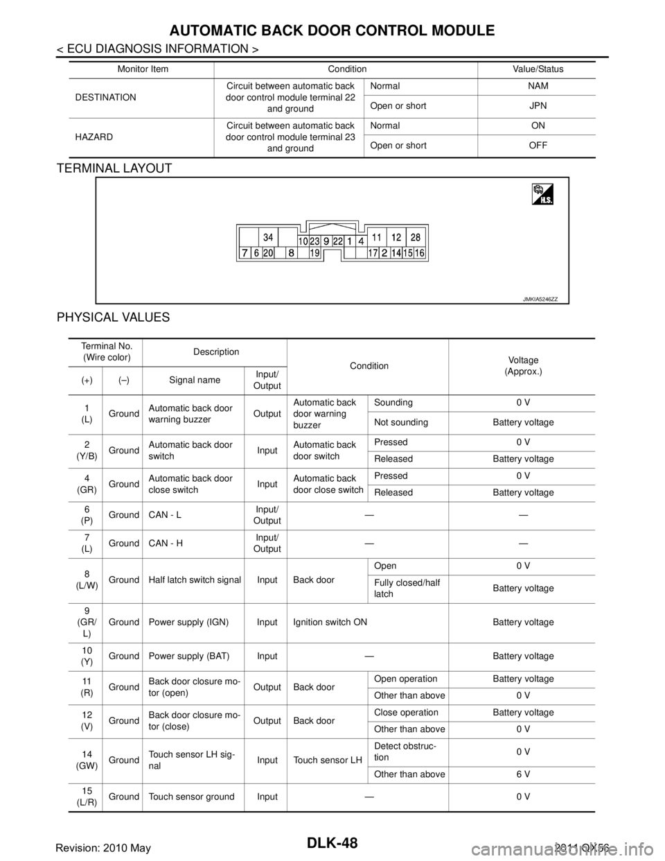
TERMINAL LAYOUT
PHYSICAL VALUES
DESTINATIONCircuit between automatic back
door control module terminal 22
and ground Normal NAM
Open or short JPN
HAZARD Circuit between automatic back
door control module terminal 23 and ground Normal ON
Open or short OFF
Monitor Item Condition Value/Status
JMKIA5246ZZ
Te r m i n a l N o .
(Wire color) Description
Condition Vo l ta g e
(Approx.)
(+) (–) Signal name Input/
Output
1
(L) Ground
Automatic back door
warning buzzer OutputAutomatic back
door warning
buzzer Sounding 0 V
Not sounding Battery voltage
2
(Y/B) Ground Automatic back door
switch InputAutomatic back
door switch Pressed 0 V
Released Battery voltage
4
(GR) Ground Automatic back door
close switch InputAutomatic back
door close switch Pressed 0 V
Released Battery voltage
6
(P) Ground CAN - L
Input/
Output ——
7
(L) Ground CAN - H Input/
Output ——
8
(L/W) Ground Half latch switch signal Input Back door Open 0 V
Fully closed/half
latch
Battery voltage
9
(GR/ L) Ground Power supply (IGN) Input Ignition switch ON Battery voltage
10
(Y) Ground Power supply (BAT) Input — Battery voltage
11
(R) Ground
Back door closure mo-
tor (open) Output Back door Open operation Battery voltage
Other than above 0 V
12
(V) Ground
Back door closure mo-
tor (close) Output Back door Close operation Battery voltage
Other than above 0 V
14
(GW) Ground Touch sensor LH sig-
nal
Input Touch sensor LH Detect obstruc-
tion
0 V
Other than above 6 V
15
(L/R) Ground Touch sensor ground Input — 0 V
Revision: 2010 May2011 QX56
Page 1585 of 5598
AUTOMATIC BACK DOOR CONTROL MODULEDLK-49
< ECU DIAGNOSIS INFORMATION >
C
DE
F
G H
I
J
L
M A
B
DLK
N
O P
Fail SafeINFOID:0000000006225861
DTC Inspection Priority ChartINFOID:0000000006225862
If some DTCs are displayed at the same time, per form inspections one by one based on the following priority
chart.
16
(LG) Ground
Touch sensor RH sig-
nal Input Touch sensor RH Detect obstruc-
tion
0 V
Other than above 6 V
17
(O) Ground Automatic back door
main switch
InputAutomatic back
door main switch ON Battery voltage
OFF 0 V
19
(L/Y) Ground Close switch signal Input Back door Fully closed 0 V
Open/half latch Battery voltage
20
(G/Y) Ground Open switch signal Input Back door Open 0 V
Half latch/fully
closed
Battery voltage
22
(B) Ground Ground (destination) — — 0 V
23
(B) Ground
Ground (Hazard re-
minder) —— 0 V
28
(R/W) Ground Power supply (BAT) Input — Battery voltage
34
(B) Ground Ground — — 0 V
Te r m i n a l N o .
(Wire color) Description
Condition Vo l ta g e
(Approx.)
(+) (–) Signal name Input/
Output
Display contents of CONSUL T-III Fail-safe Cancellation
B2401 IGN OPEN Intermittent clutch function All following condition are satisfied
Power supply condition of auto-
matic back door control unit: OFF
BCM receive ignition position sig- nal (OFF) via CAN
B2403 PULSE ENCODER Inhibit automatic back door operation When receiving the pulse from en-
coders A and B normally (5 pulses)
B2409 HALF LATCH SW Intermittent clutch function Half latch switch is ON from OFF
B2416 TOUCH SEN R OPEN During close operation: Intermittent clutch
function
Normal return
B2417 TOUCH SEN L OPEN During close operation: Intermittent clutch
function Normal return
B2419 OPEN SW Inhibit automatic back door operation Erase DTC, reconnect battery
B2420 CLOSE SW Inhibit automatic back door operation Erase DTC, reconnect battery
B2421 CLUTCH TIME OUT Intermittent clutch function Reception of next operation request
B2422 BACK DOOR STATE Intermittent clutch function Detect back door fully closed posi-
tion
B2423 ABD MTR TIME OUT Intermittent clutch function Reception of next operation request
B2424 CLSR CONDITION Inhibit automatic back door operation Normal return or reconnect battery
Revision: 2010 May2011 QX56
Page 1620 of 5598
DLK-84
< DTC/CIRCUIT DIAGNOSIS >
B2401 IGNITION POWER SUPPLY CIRCUIT
B2401 IGNITION POWER SUPPLY CIRCUIT
DTC LogicINFOID:0000000006225878
DTC DETECTION LOGIC
DTC CONFIRMATION PROCEDURE
1.PERFORM DTC CONFIRMATION PROCEDURE
1. Turn ignition switch ON and wait for at least 1 second.
2. Check “Self Diagnostic Result” mode of “AUTOMAT IC BACK DOOR CONTROL UNIT” using CONSULT-
III.
Is DTC detected?
YES >> Refer to DLK-84, "Diagnosis Procedure".
NO >> INSPECTION END
Diagnosis ProcedureINFOID:0000000006225879
1.CHECK FUSE
1. Turn ignition switch OFF.
2. Check 10A fuse, [No. 4, located in fuse block (J/B)].
Is the inspection result normal?
YES >> GO TO 2.
NO >> Replace the blown fuse after repairing the affected circuit if a fuse is blown.
2.CHECK POWER SUPPLY CIRCUIT
1. Turn ignition switch OFF.
2. Disconnect automatic back door control unit connector.
3. Check voltage between automatic back door control unit harness connector and ground.
Is the measurement value normal?
YES >> Check intermittent incident. Refer to GI-40, "Intermittent Incident".
NO >> Repair or replace harness.
DTC CONSULT-III display
description DTC detecting condition Possible cause
B2401 IGN OPEN When the automatic back door control unit detects
the following condition for 0.3 second or more
Power supply condition (OFF) of automatic back
door control unit and Ignition position signal (ON)
from BCM via CAN Fuse
Harness or connectors
(Ignition power supply condition
circuit is open or shorted)
(+)
(− ) Condition Vo l ta g e
(Approx.)
Automatic back door control unit
Connector Terminal
B26 9 Ground Ignition switch ON Battery voltage
OFF 0 V
Revision: 2010 May2011 QX56
Page 1621 of 5598

B2403 ENCODERDLK-85
< DTC/CIRCUIT DIAGNOSIS >
C
DE
F
G H
I
J
L
M A
B
DLK
N
O P
B2403 ENCODER
DTC LogicINFOID:0000000006225880
DTC DETECTION LOGIC
DTC CONFIRMATION PROCEDURE
1.PERFORM DTC CONFIRMATION PROCEDURE
1. Turn ignition switch ON.
2. Check “Self Diagnostic Result” mode of “AUTOMAT IC BACK DOOR CONTROL UNIT” using CONSULT-
III.
Is DTC detected?
YES >> Refer to DLK-85, "Diagnosis Procedure".
NO >> INSPECTION END
Diagnosis ProcedureINFOID:0000000006225881
1.CHECK AUTOMATIC BACK DOOR CONTROL MODULE POWER SUPPLY AND GROUND CIRCUIT
1. Turn ignition switch OFF.
2. Check automatic back door control module power supply and ground circuit. Refer to DLK-116, "
AUTOMATIC BACK DOOR CONTROL UNIT : Diagnosis Procedure".
Is the inspection result normal?
YES >> Replace automatic back door control module. Refer to DLK-262, "Removal and Installation".
NO >> Repair or replace the malfunctioning parts.
DTC CONSULT-III dis-
play description DTC detecting condition Possible cause
B2403 PULSE ENCODER When the automatic back door control unit can not re-
ceive the signal from the encoder just after starting the
open/close operation Battery voltage (low battery)
Automatic back door control mod-
ule
Revision: 2010 May2011 QX56
Page 1622 of 5598
DLK-86
< DTC/CIRCUIT DIAGNOSIS >
B2409 HALF LATCH SWITCH
B2409 HALF LATCH SWITCH
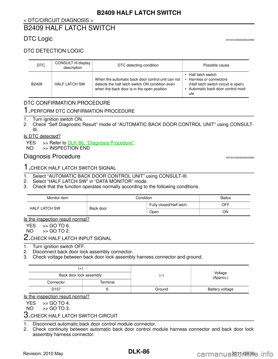
DTC LogicINFOID:0000000006225882
DTC DETECTION LOGIC
DTC CONFIRMATION PROCEDURE
1.PERFORM DTC CONFIRMATION PROCEDURE
1. Turn ignition switch ON.
2. Check “Self Diagnostic Result” mode of “AUTOMAT IC BACK DOOR CONTROL UNIT” using CONSULT-
III.
Is DTC detected?
YES >> Refer to DLK-86, "Diagnosis Procedure".
NO >> INSPECTION END
Diagnosis ProcedureINFOID:0000000006225883
1.CHECK HALF LATCH SWITCH SIGNAL
1. Select “AUTOMATIC BACK DOOR CONTROL UNIT” using CONSULT-III.
2. Select “HALF LATCH SW” in “DATA MONITOR” mode.
3. Check that the function operates normall y according to the following conditions.
Is the inspection result normal?
YES >> GO TO 6.
NO >> GO TO 2.
2.CHECK HALF LATCH INPUT SIGNAL
1. Turn ignition switch OFF.
2. Disconnect back door lock assembly connector.
3. Check voltage between back door lock assembly harness connector and ground.
Is the inspection result normal?
YES >> GO TO 4.
NO >> GO TO 3.
3.CHECK HALF LATCH SWITCH CIRCUIT
1. Disconnect automatic back door control module connector.
2. Check continuity between automatic back door control module harness connector and back door lock
assembly harness connector.
DTC CONSULT-III display
description DTC detecting condition Possible cause
B2409 HALF LATCH SW When the automatic back door control unit can not
detects the half latch switch ON condition even
when the back door is in the open position Half latch switch
Harness or connectors
(Half latch switch circuit is open)
Automatic back door control mod-
ule
Monitor item Condition Status
HALF LATCH SW Back door Fully closed/Half latch OFF
Open ON
(+)
(–)Voltag e
(Approx.)
Back door lock assembly
Connector Terminal D157 6 Ground Battery voltage
Revision: 2010 May2011 QX56
Page 1623 of 5598
B2409 HALF LATCH SWITCHDLK-87
< DTC/CIRCUIT DIAGNOSIS >
C
DE
F
G H
I
J
L
M A
B
DLK
N
O P
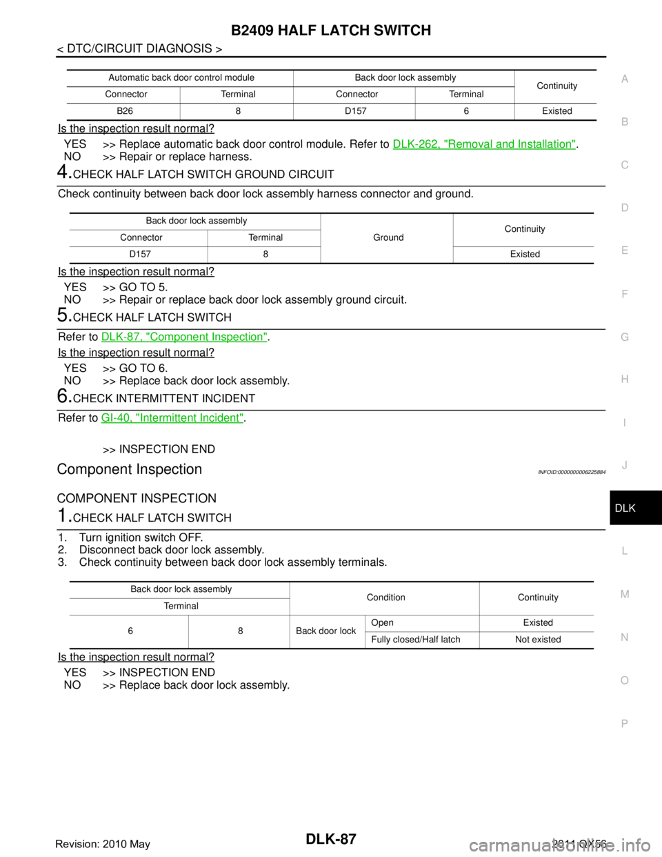
Is the inspection result normal?
YES >> Replace automatic back door control module. Refer to DLK-262, "Removal and Installation".
NO >> Repair or replace harness.
4.CHECK HALF LATCH SWITCH GROUND CIRCUIT
Check continuity between back door lo ck assembly harness connector and ground.
Is the inspection result normal?
YES >> GO TO 5.
NO >> Repair or replace back door lock assembly ground circuit.
5.CHECK HALF LATCH SWITCH
Refer to DLK-87, "
Component Inspection".
Is the inspection result normal?
YES >> GO TO 6.
NO >> Replace back door lock assembly.
6.CHECK INTERMITTENT INCIDENT
Refer to GI-40, "
Intermittent Incident".
>> INSPECTION END
Component InspectionINFOID:0000000006225884
COMPONENT INSPECTION
1.CHECK HALF LATCH SWITCH
1. Turn ignition switch OFF.
2. Disconnect back door lock assembly.
3. Check continuity between back door lock assembly terminals.
Is the inspection result normal?
YES >> INSPECTION END
NO >> Replace back door lock assembly.
Automatic back door control module Back door lock assembly Continuity
Connector Terminal Connector Terminal
B26 8 D157 6 Existed
Back door lock assembly GroundContinuity
Connector Terminal
D157 8 Existed
Back door lock assembly Condition Continuity
Te r m i n a l
6 8 Back door lock Open Existed
Fully closed/Half latch Not existed
Revision: 2010 May2011 QX56