2011 INFINITI QX56 recommended oil
[x] Cancel search: recommended oilPage 3677 of 5598
PERIODIC MAINTENANCEMA-7
< PERIODIC MAINTENANCE >
C
DE
F
G H
I
J
K L
M B
MA
N
O A
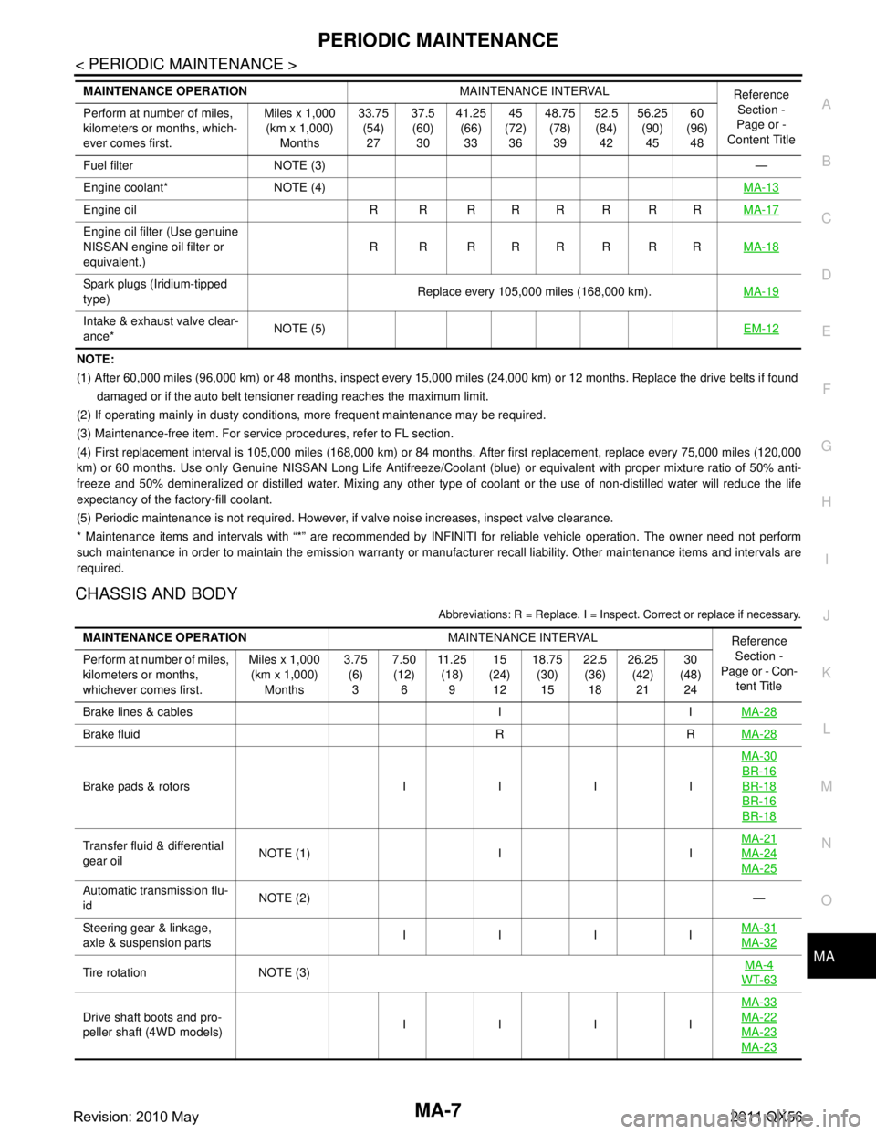
NOTE:
(1) After 60,000 miles (96,000 km) or 48 months, inspect every 15,000 miles (24,000 km) or 12 months. Replace the drive belts i
f found
damaged or if the auto belt tensioner reading reaches the maximum limit.
(2) If operating mainly in dusty conditions, more frequent maintenance may be required.
(3) Maintenance-free item. For service procedures, refer to FL section.
(4) First replacement interval is 105,000 miles (168,000 km) or 84 months. After first replacement, replace every 75,000 miles (120,000
km) or 60 months. Use only Genu ine NISSAN Long Life Antifreeze/Coo lant (blue) or equivalent with proper mixture ratio of 50% anti-
freeze and 50% demineralized or distilled water. Mixing any other type of coolant or the use of non-distilled water will reduce the life
expectancy of the factory-fill coolant.
(5) Periodic maintenance is not required. However, if valve noise increases, inspect valve clearance.
* Maintenance items and intervals with “*” are recommended by INFINITI for reliable vehicle operation. The owner need not perfo rm
such maintenance in order to maintain the emission warranty or manufacturer recall liability. Other maintenance items and inter vals are
required.
CHASSIS AND BODY
Abbreviations: R = Replace. I = Inspec t. Correct or replace if necessary.
Fuel filter NOTE (3) —
Engine coolant* NOTE (4) MA-13
Engine oil R R R R R R R RMA-17
Engine oil filter (Use genuine
NISSAN engine oil filter or
equivalent.)R R RRRRRR
MA-18
Spark plugs (Iridium-tipped
type)Replace every 105,000 miles (168,000 km).
MA-19
Intake & exhaust valve clear-
ance*NOTE (5)
EM-12
MAINTENANCE OPERATIONMAINTENANCE INTERVAL
Reference
Section -
Page or -
Content Title
Perform at number of miles,
kilometers or months, which-
ever comes first. Miles x 1,000
(km x 1,000)
Months 33.75
(54)
27 37.5
(60)
30 41.25
(66)
33 45
(72)
36 48.75
(78)
39 52.5
(84)
42 56.25
(90)
45 60
(96)
48
MAINTENANCE OPERATION MAINTENANCE INTERVAL
Reference
Section -
Page or - Con- tent Title
Perform at number of miles,
kilometers or months,
whichever comes first. Miles x 1,000
(km x 1,000)
Months 3.75
(6)
3 7.50
(12)
6 11 . 2 5
(18)
9 15
(24)
12 18.75
(30)
15 22.5
(36)
18 26.25
(42)
21 30
(48)
24
Brake lines & cables I I MA-28
Brake fluid R RMA-28
Brake pads & rotors I I I IMA-30
BR-16
BR-18
BR-16
BR-18
Transfer fluid & differential
gear oil
NOTE (1) I I MA-21MA-24
MA-25
Automatic transmission flu-
id
NOTE (2)
—
Steering gear & linkage,
axle & suspension parts IIII
MA-31
MA-32
Tire rotation NOTE (3) MA-4WT-63
Drive shaft boots and pro-
peller shaft (4WD models) IIII MA-33MA-22
MA-23
MA-23
Revision: 2010 May2011 QX56
Page 3679 of 5598
PERIODIC MAINTENANCEMA-9
< PERIODIC MAINTENANCE >
C
DE
F
G H
I
J
K L
M B
MA
N
O A
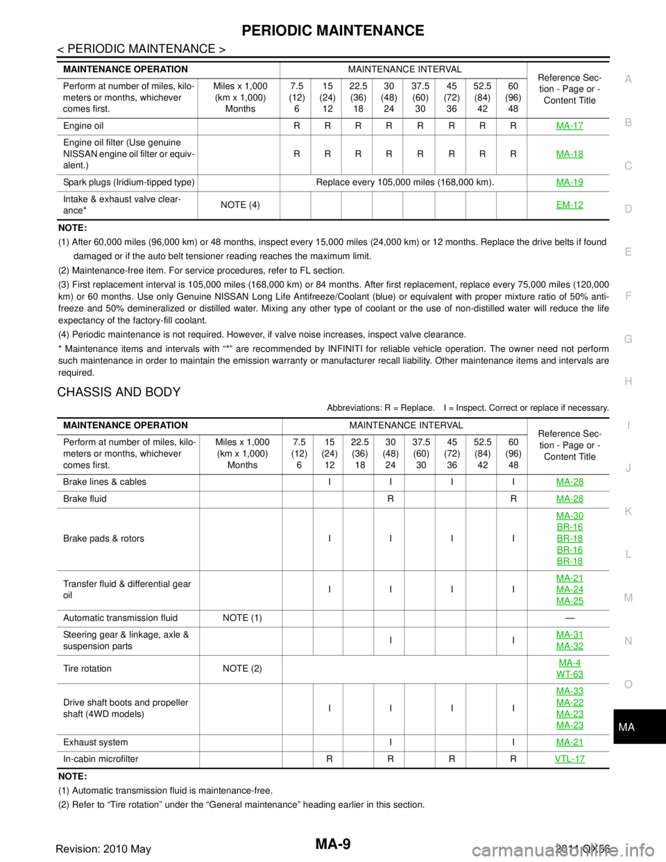
NOTE:
(1) After 60,000 miles (96,000 km) or 48 months, inspect every 15,000 miles (24,000 km) or 12 months. Replace the drive belts i
f found
damaged or if the auto belt tensioner reading reaches the maximum limit.
(2) Maintenance-free item. For service procedures, refer to FL section.
(3) First replacement interval is 105,000 miles (168,000 km) or 84 months. After first replacement, replace every 75,000 miles (120,000
km) or 60 months. Use only Genu ine NISSAN Long Life Antifreeze/Coo lant (blue) or equivalent with proper mixture ratio of 50% anti-
freeze and 50% demineralized or distilled water. Mixing any other type of coolant or the use of non-distilled water will reduce the life
expectancy of the factory-fill coolant.
(4) Periodic maintenance is not required. However, if valve noise increases, inspect valve clearance.
* Maintenance items and intervals with “*” are recommended by INFINITI for reliable vehicle operation. The owner need not perfo rm
such maintenance in order to maintain the emission warranty or manufacturer recall liability. Other maintenance items and inter vals are
required.
CHASSIS AND BODY
Abbreviations: R = Replace. I = Inspec t. Correct or replace if necessary.
NOTE:
(1) Automatic transmission fluid is maintenance-free.
(2) Refer to “Tire rotation” under the “General maintenance” heading earlier in this section.
Engine oil R R R R R R R R
MA-17
Engine oil filter (Use genuine
NISSAN engine oil filter or equiv-
alent.)RRRR R RRR
MA-18
Spark plugs (Iridium-tipped type) Replace every 105,000 miles (168,000 km). MA-19
Intake & exhaust valve clear-
ance*NOTE (4)
EM-12
MAINTENANCE OPERATIONMAINTENANCE INTERVAL
Reference Sec-
tion - Page or -
Content Title
Perform at number of miles, kilo-
meters or months, whichever
comes first. Miles x 1,000
(km x 1,000)
Months 7.5
(12)
6 15
(24)
12 22.5
(36)
18 30
(48)
24 37.5
(60)
30 45
(72)
36 52.5
(84)
42 60
(96)
48
MAINTENANCE OPERATION MAINTENANCE INTERVAL
Reference Sec-
tion - Page or - Content Title
Perform at number of miles, kilo-
meters or months, whichever
comes first. Miles x 1,000
(km x 1,000) Months 7.5
(12) 6 15
(24) 12 22.5
(36) 18 30
(48) 24 37.5
(60) 30 45
(72) 36 52.5
(84) 42 60
(96) 48
Brake lines & cables I I I I MA-28
Brake fluid R RMA-28
Brake pads & rotors I I I IMA-30
BR-16
BR-18
BR-16
BR-18
Transfer fluid & differential gear
oil
IIIIMA-21MA-24
MA-25
Automatic transmission fluid NOTE (1)
—
Steering gear & linkage, axle &
suspension parts II
MA-31
MA-32
Tire rotation NOTE (2) MA-4WT-63
Drive shaft boots and propeller
shaft (4WD models) IIIIMA-33MA-22
MA-23
MA-23
Exhaust system I I
MA-21
In-cabin microfilter R R R RVTL-17
Revision: 2010 May2011 QX56
Page 3680 of 5598

MA-10
< PERIODIC MAINTENANCE >
RECOMMENDED FLUIDS AND LUBRICANTS
RECOMMENDED FLUIDS AND LUBRICANTS
Fluids and LubricantsINFOID:0000000006220904
*1: For further details, see “Engine Oil Recommendation”.
*2: Using automatic transmission fluid other than Genuine NISSAN Matic S ATF will cause deterioration in driveability and autom atic
transmission durability, and may damage the automatic transmission, which is not covered by the INFINITI new vehicle limited wa rranty.
*3: DEXRON™ VI type ATF may also be used.
*4: Available in mainland U.S.A. through an INFINITI dealer.
*5: Using transfer fluid other t han Genuine NISSAN Transfer Fluid will damage the transfer , which is not covered by the INFINITI new
vehicle limited warranty. See an INFINITI retailer for recommended transfer fluid.
*6: For hot climates, Viscosity SAE 90 is suitable for ambient temperatures above 0 °C (32 °F)
*7: See an INFINITI dealer for service for synthetic oil.
*8: Using Hydraulic Suspen sion fluid other than Genuine NISSAN Hydraulic Susp ension fluid will damage the Hydraulic Suspension,
which is not covered by the INFINITI new vehicle limited warranty. See an INFINITI retailer for recommended hydraulic suspensio n fluid.
*9: The fluid capacity is the reference value.
Engine Oil RecommendationINFOID:0000000006287732
NISSAN recommends the use of an energy conservi ng oil in order to improve fuel economy.
Select only engine oils that meet the American Petroleum Institute (API) certification and International Lubri-
cant Standardization and Approval Committee (ILSAC) ce rtification and SAE viscosity standard. These oils
have the API certification mark on t he front of the container. Oils which do not have the specified quality label
should not be used as they could cause engine damage.
Capacity (Approximate) Recommended Fluids/Lubricants
US measure Imp measure Liter
Engine oil
Drain and refill With oil filter change 6-7/8 qt 5-3/4 qt 6.5
Engine oil with API Certification Mark
*1
Viscosity SAE 5W-30
Without oil filter change 6-4/8 qt 5-1/2 qt 6.2
Dry engine (engine overhaul) 8 qt 6-3/4 qt 7.6
Cooling system With reservoir tank 15
-6/8 qt 13-1/8 qt 14.9
Genuine NISSAN Long Life Antifreeze/
Coolant (blue) or equivalent
Reservoir tank 1 qt 7/8 qt 1.0
Automatic transmission fluid 10-5/8 qt
*98-3/4 qt*910.0*9Genuine NISSAN Matic S ATF *2
Power steering fluid 1-1/8 qt 7/8 qt 1.0
Genuine NISSAN PSF or equivalent*3
Brake fluid — — —Genuine NISSAN Super Heavy Duty
Brake Fluid*4 or equivalent DOT 3 (US FM-
VSS No. 116)
Transfer fluid 3-1/8 pt 2-5/8 pt 1.5 Genuine NISSAN Transfer Fluid for
ATX90A transfer*
5
Differential gear oilFront 1-5/8 pt 1-3/8 pt 0.75
Genuine NISSAN Differential Oil Hypoid
Super GL-5 80W-90 or API GL-5, Viscosity
SAE 80W-90*
6
Rear 3/3/4 pt 3-1/8 pt 1.75Genuine NISSAN Differential Oil Synthetic
75W-90 or API GL-5 synthetic gear oil, Vis-
cosity SAE 75W-90*7
Suspension fluid — — —
Genuine NISSAN Hydraulic Suspension
Fluid*8
Multi-purpose grease — — — NLGI No. 2 (Lithium soap base)
Revision: 2010 May2011 QX56
Page 3702 of 5598
MA-32
< PERIODIC MAINTENANCE >
CHASSIS MAINTENANCE
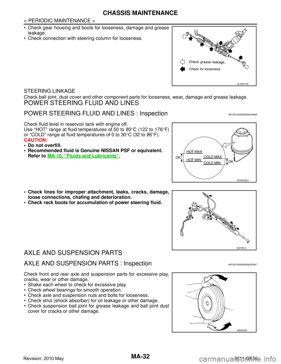
Check gear housing and boots for looseness, damage and greaseleakage.
Check connection with steering column for looseness.
STEERING LINKAGE
Check ball joint, dust cover and other component parts for looseness, wear, damage and grease leakage.
POWER STEERING FLUID AND LINES
POWER STEERING FLUID AND LINES : InspectionINFOID:0000000006220946
Check fluid level in reservoir tank with engine off.
Use “HOT” range at fluid temperatures of 50 to 80 °C (122 to 176 °F)
or “COLD” range at fluid temperatures of 0 to 30 °C (32 to 86 °F).
CAUTION:
Do not overfill.
Recommended fluid is Genuine NISSAN PSF or equivalent.
Refer to MA-10, "
Fluids and Lubricants".
Check lines for improper attachment, leaks, cracks, damage, loose connections, chaf ing and deterioration.
Check rack boots for accumulati on of power steering fluid.
AXLE AND SUSPENSION PARTS
AXLE AND SUSPENSION PARTS : InspectionINFOID:0000000006220947
Check front and rear axle and suspension parts for excessive play,
cracks, wear or other damage.
Shake each wheel to check for excessive play.
Check wheel bearings for smooth operation.
Check axle and suspension nuts and bolts for looseness.
Check strut (shock absorber) for oil leakage or other damage.
Check suspension ball joint for grease leakage and ball joint dust
cover for cracks or other damage.
SLIA0014E
SGIA0232J
SST851C
SMA525A
Revision: 2010 May2011 QX56
Page 5017 of 5598
ST-30
< PERIODIC MAINTENANCE >
POWER STEERING FLUID
PERIODIC MAINTENANCE
POWER STEERING FLUID
InspectionINFOID:0000000006225597
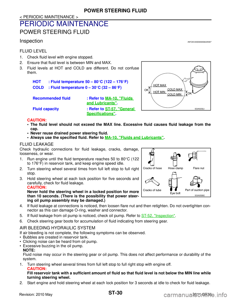
FLUID LEVEL
1. Check fluid level with engine stopped.
2. Ensure that fluid level is between MIN and MAX.
3. Fluid levels at HOT and COLD are different. Do not confuse
them.
CAUTION:
The fluid level should not exceed the MAX line. Excessive flui d causes fluid leakage from the
cap.
Never reuse drained power steering fluid.
Always use the specified fluid. Refer to MA-10, "
Fluids and Lubricants".
FLUID LEAKAGE
Check hydraulic connections for fluid leakage, cracks, damage,
looseness, or wear.
1. Run engine until the fluid temperature reaches 50 to 80 °C (122
to 176 °F) in reservoir tank, and keep engine speed idle.
2. Turn steering wheel several times from full left stop to full right stop.
3. Hold steering wheel at each lock position for five seconds and carefully, check for fluid leakage.
CAUTION:
Never hold the steering wheel in a locked position for more
than 10 seconds. (There is the possibility that power steer-
ing oil pump assembly may be damaged.)
4. If fluid leakage at connections is noticed, then loos en flare nut and then retighten. Do not overtighten con-
nector as this can damage O-ring, washer and connector.
5. If fluid leakage from oil pump is noticed, check oil pump. Refer to ST-52, "
Inspection".
6. Check steering gear boots for accumulation of fluid indicating from steering gear.
AIR BLEEDING HYDRAULIC SYSTEM
If air bleeding is not complete, the following symptoms can be observed.
Bubbles are created in reservoir tank.
Clicking noise can be heard from oil pump.
Excessive buzzing in the oil pump. NOTE:
Fluid noise may occur in the steering gear or oil pump. This does not affect performance or durability of the
system.
1. Turn steering wheel several times from full left stop to full right stop with engine off. CAUTION:
Fill reservoir tank with a sufficien t amount of fluid so that fluid level is not below the MIN line while
turning steering wheel.
2. Start engine and hold steering wheel at each lock position for 3 seconds at idle to check for fluid leakage.
HOT : Fluid temperature 50 – 80
°C (122 – 176 °F)
COLD : Fluid temperature 0 – 30 °C (32 – 86 °F)
Recommended fluid : Refer to MA-10, "
Fluids
and Lubricants".
Fluid capacity : Refer to ST-57, "
General
Specifications".
SGIA0232J
SGIA0506E
Revision: 2010 May2011 QX56
Page 5031 of 5598
ST-44
< REMOVAL AND INSTALLATION >
STEERING GEAR AND LINKAGE
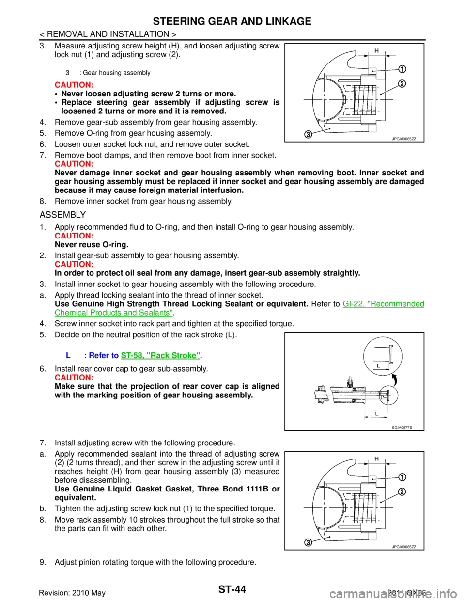
3. Measure adjusting screw height (H), and loosen adjusting screwlock nut (1) and adjusting screw (2).
CAUTION:
Never loosen adjusting screw 2 turns or more.
Replace steering gear assembly if adjusting screw is
loosened 2 turns or more and it is removed.
4. Remove gear-sub assembly from gear housing assembly.
5. Remove O-ring from gear housing assembly.
6. Loosen outer socket lock nut, and remove outer socket.
7. Remove boot clamps, and then remove boot from inner socket. CAUTION:
Never damage inner socket and gear housing assembly when removing boot. Inner socket and
gear housing assembly must be replaced if inne r socket and gear housing assembly are damaged
because it may cause foreign material interfusion.
8. Remove inner socket from gear housing assembly.
ASSEMBLY
1. Apply recommended fluid to O-ring, and then install O-ring to gear housing assembly. CAUTION:
Never reuse O-ring.
2. Install gear-sub assembly to gear housing assembly. CAUTION:
In order to protect oil seal from any da mage, insert gear-sub assembly straightly.
3. Install inner socket to gear housing assembly with the following procedure.
a. Apply thread locking sealant into the thread of inner socket. Use Genuine High Strength Thread Locking Sealant or equivalent. Refer to GI-22, "
Recommended
Chemical Products and Sealants".
4. Screw inner socket into rack part and tighten at the specified torque.
5. Decide on the neutral position of the rack stroke (L).
6. Install rear cover cap to gear sub-assembly. CAUTION:
Make sure that the projection of rear cover cap is aligned
with the marking position of gear housing assembly.
7. Install adjusting screw with the following procedure.
a. Apply recommended sealant into the thread of adjusting screw (2) (2 turns thread), and then screw in the adjusting screw until it
reaches height (H) from gear housing assembly (3) measured
before disassembling.
Use Genuine Liquid Gasket Gasket, Three Bond 1111B or
equivalent.
b. Tighten the adjusting screw lock nut (1) to the specified torque.
8. Move rack assembly 10 strokes throughout the full stroke so that the parts can fit with each other.
9. Adjust pinion rotating torque with the following procedure.
3 : Gear housing assembly
JPGIA0065ZZ
L : Refer to ST-58, "Rack Stroke".
SGIA0877E
JPGIA0065ZZ
Revision: 2010 May2011 QX56
Page 5038 of 5598
POWER STEERING OIL PUMPST-51
< REMOVAL AND INSTALLATION >
C
DE
F
H I
J
K L
M A
B
ST
N
O P
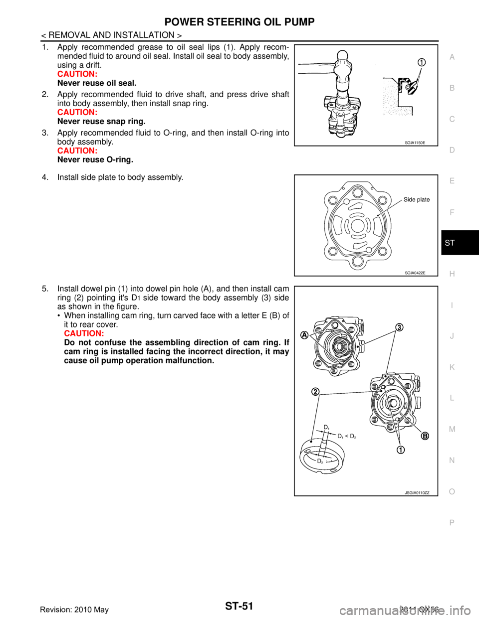
1. Apply recommended grease to oil seal lips (1). Apply recom- mended fluid to around oil seal. Install oil seal to body assembly,
using a drift.
CAUTION:
Never reuse oil seal.
2. Apply recommended fluid to drive shaft, and press drive shaft into body assembly, then install snap ring.
CAUTION:
Never reuse snap ring.
3. Apply recommended fluid to O-ring, and then install O-ring into body assembly.
CAUTION:
Never reuse O-ring.
4. Install side plate to body assembly.
5. Install dowel pin (1) into dowel pin hole (A), and then install cam ring (2) pointing it's D
1 side toward the body assembly (3) side
as shown in the figure.
When installing cam ring, turn carved face with a letter E (B) of
it to rear cover.
CAUTION:
Do not confuse the assembling direction of cam ring. If
cam ring is installed facing th e incorrect direction, it may
cause oil pump operation malfunction.
SGIA1150E
SGIA0422E
JSGIA0110ZZ
Revision: 2010 May2011 QX56
Page 5039 of 5598
ST-52
< REMOVAL AND INSTALLATION >
POWER STEERING OIL PUMP
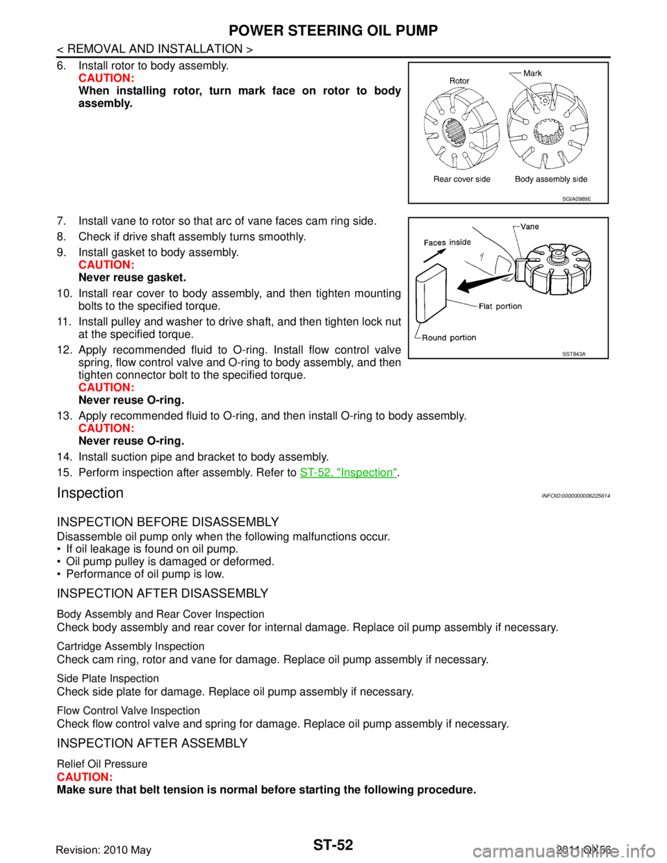
6. Install rotor to body assembly.CAUTION:
When installing rotor, turn mark face on rotor to body
assembly.
7. Install vane to rotor so that arc of vane faces cam ring side.
8. Check if drive shaft assembly turns smoothly.
9. Install gasket to body assembly. CAUTION:
Never reuse gasket.
10. Install rear cover to body assembly, and then tighten mounting bolts to the specified torque.
11. Install pulley and washer to drive shaft, and then tighten lock nut at the specified torque.
12. Apply recommended fluid to O-ring. Install flow control valve spring, flow control valve and O-ring to body assembly, and then
tighten connector bolt to the specified torque.
CAUTION:
Never reuse O-ring.
13. Apply recommended fluid to O-ring, and then install O-ring to body assembly. CAUTION:
Never reuse O-ring.
14. Install suction pipe and bracket to body assembly.
15. Perform inspection after assembly. Refer to ST-52, "
Inspection".
InspectionINFOID:0000000006225614
INSPECTION BEFORE DISASSEMBLY
Disassemble oil pump only when the following malfunctions occur.
If oil leakage is found on oil pump.
Oil pump pulley is damaged or deformed.
Performance of oil pump is low.
INSPECTION AFTER DISASSEMBLY
Body Assembly and Rear Cover Inspection
Check body assembly and rear cover for internal damage. Replace oil pump assembly if necessary.
Cartridge Assembly Inspection
Check cam ring, rotor and vane for damage. Replace oil pump assembly if necessary.
Side Plate Inspection
Check side plate for damage. Replace oil pump assembly if necessary.
Flow Control Valve Inspection
Check flow control valve and spring for damage. Replace oil pump assembly if necessary.
INSPECTION AFTER ASSEMBLY
Relief Oil Pressure
CAUTION:
Make sure that belt tension is normal before starting the following procedure.
SGIA0989E
SST843A
Revision: 2010 May2011 QX56