Page 2675 of 5598
CYLINDER BLOCKEM-113
< UNIT DISASSEMBLY AND ASSEMBLY >
C
DE
F
G H
I
J
K L
M A
EM
NP
O
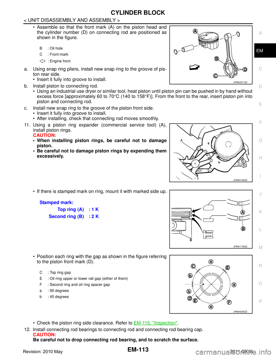
Assemble so that the front mark (A) on the piston head and
the cylinder number (D) on connecting rod are positioned as
shown in the figure.
a. Using snap ring pliers, install new snap ring to the groove of pis- ton rear side.
Insert it fully into groove to install.
b. Install piston to connecting rod. Using an industrial use dryer or similar tool, heat piston until piston pin can be pushed in by hand without
excess force [approximately 60 to 70 °C (140 to 158 °F)]. From the front to the rear, insert piston pin into
piston and connecting rod.
c. Install new snap ring to the groove of the piston front side. Insert it fully into groove to install.
After installing, check that connecting rod moves smoothly.
11. Using a piston ring expander (c ommercial service tool) (A),
install piston rings.
CAUTION:
When installing piston rings, be careful not to damage piston.
Be careful not to damage piston rings by expending them excessively.
If there is stamped mark on ri ng, mount it with marked side up.
Position each ring with the gap as shown in the figure referring to the piston front mark (D).
Check the piston ring side clearance. Refer to EM-115, "
Inspection".
12. Install connecting rod bearings to connecting rod and connecting rod bearing cap. CAUTION:
Be careful not to drop connecting r od bearing, and to scratch the surface.
B : Oil hole
C : Front mark
: Engine front
JPBIA2271ZZ
JPBIA0194ZZ
Stamped mark: To p r i n g ( A ) : 1 K
Second ring (B) : 2 K
JPBIA1720ZZ
C : Top ring gap
E : Oil ring upper or lower rail gap (either of them)
F : Second ring and oil ring spacer gap
a : 90 degrees
b : 45 degrees
JPBIA0205ZZ
Revision: 2010 May2011 QX56
Page 2687 of 5598
HOW TO SELECT PISTON AND BEARINGEM-125
< UNIT DISASSEMBLY AND ASSEMBLY >
C
DE
F
G H
I
J
K L
M A
EM
NP
O
HOW TO SELECT PISTON AND BEARING
DescriptionINFOID:0000000006289585
The identification grade stamped on each part is the
grade for the dimension measured in new condition.
This grade cannot apply to reused parts.
For reused or repaired parts, measure the dimens ion accurately. Determine the grade by comparing the
measurement with the values of each selection table.
For details of the measurement method of each part , the reuse standards and the selection method of the
selective fitting parts, refer to the text.
PistonINFOID:0000000006289586
WHEN NEW CYLINDER BLOCK IS USED
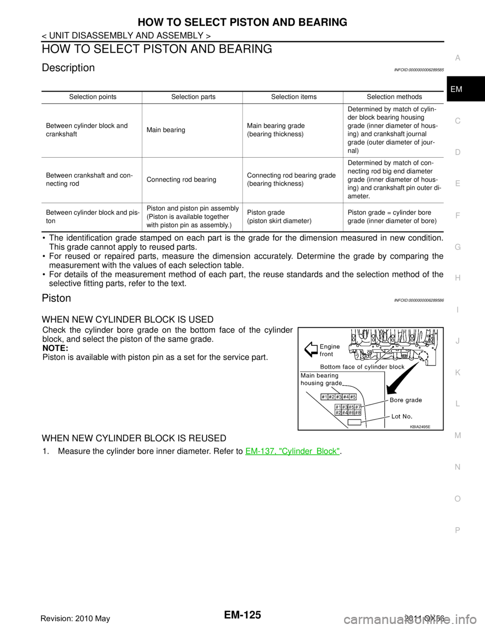
Check the cylinder bore grade on the bottom face of the cylinder
block, and select the piston of the same grade.
NOTE:
Piston is available with piston pin as a set for the service part.
WHEN NEW CYLINDER BLOCK IS REUSED
1. Measure the cylinder bore inner diameter. Refer to EM-137, "CylinderBlock".
Selection points Selection parts Selection items Selection methods
Between cylinder block and
crankshaft Main bearing Main bearing grade
(bearing thickness)Determined by match of cylin-
der block bearing housing
grade (inner diameter of hous-
ing) and crankshaft journal
grade (outer diameter of jour-
nal)
Between crankshaft and con-
necting rod Connecting rod bearing Connecting rod bearing grade
(bearing thickness)Determined by match of con-
necting rod big end diameter
grade (inner diameter of hous-
ing) and crankshaft pin outer di-
ameter.
Between cylinder block and pis-
ton Piston and piston pin assembly
(Piston is available together
with piston pin as assembly.) Piston grade
(piston skirt diameter)
Piston grade = cylinder bore
grade (inner diameter of bore)
KBIA2495E
Revision: 2010 May2011 QX56
Page 2690 of 5598
![INFINITI QX56 2011 Factory Service Manual
EM-128
< UNIT DISASSEMBLY AND ASSEMBLY >
HOW TO SELECT PISTON AND BEARING
In grinding crankshaft pin to use undersize bearings, keep the
fillet R (A) [1.5 - 1.7 mm (0.059 - 0.067 in)].
Main BearingIN INFINITI QX56 2011 Factory Service Manual
EM-128
< UNIT DISASSEMBLY AND ASSEMBLY >
HOW TO SELECT PISTON AND BEARING
In grinding crankshaft pin to use undersize bearings, keep the
fillet R (A) [1.5 - 1.7 mm (0.059 - 0.067 in)].
Main BearingIN](/manual-img/42/57033/w960_57033-2689.png)
EM-128
< UNIT DISASSEMBLY AND ASSEMBLY >
HOW TO SELECT PISTON AND BEARING
In grinding crankshaft pin to use undersize bearings, keep the
fillet R (A) [1.5 - 1.7 mm (0.059 - 0.067 in)].
Main BearingINFOID:0000000006289588
WHEN NEW CYLINDER BLOCK AND CRANKSHAFT ARE USED
1. Apply the main bearing housing grade on the bottom face of thecylinder block to the row in “MAIN BEARING SELECTION
TA B L E ” .
2. “MAIN BEARING SELECTION TABLE” columns correspond to
journal diameter grade on front side of crankshaft.
3. Select main bearing grade at the point where selected row and column meet in “MAIN BEARING SELEC- TION TABLE”.
CAUTION:
Initial clearance for No. 1, 5 journal and No. 2, 3, 4 journal is different. Use two different selection
table for each part.
No. 1, 5 journal and No. 2, 3, 4 journal have the same signs but different measures. Never con-
fuse.
4. Apply sign at crossing in above step 3 to “MAIN BEARING GRADE TABLE”.
NOTE:
“MAIN BEARING GRADE TABLE” applies to all journals.
Service parts are available as a set of both upper and lower.
WHEN CYLINDER BLOCK AND CRANKSHAFT ARE REUSED
1. Measure cylinder block main bearing housing inner diameter and crankshaft main journal diameter. Refer to EM-115, "
Inspection".
JPBIA0216ZZ
Bearing undersize table : Refer to EM-142, "ConnectingRodBearing".
KBIA2495E
A : Pin diameter grade No. 1
B : Pin diameter grade No. 2
C : Pin diameter grade No. 3
D : Pin diameter grade No. 4
E : Journal diameter grade No. 1
F : Journal diameter grade No. 2
G : Journal diameter grade No. 3
H : Journal diameter grade No. 4
I : Journal diameter grade No. 5
JPBIA2283ZZ
Revision: 2010 May2011 QX56
Page 2694 of 5598
EM-132
< SERVICE DATA AND SPECIFICATIONS (SDS)
SERVICE DATA AND SPECIFICATIONS (SDS)
SERVICE DATA AND SPECIFICATIONS (SDS)
SERVICE DATA AND SPECIFICATIONS (SDS)
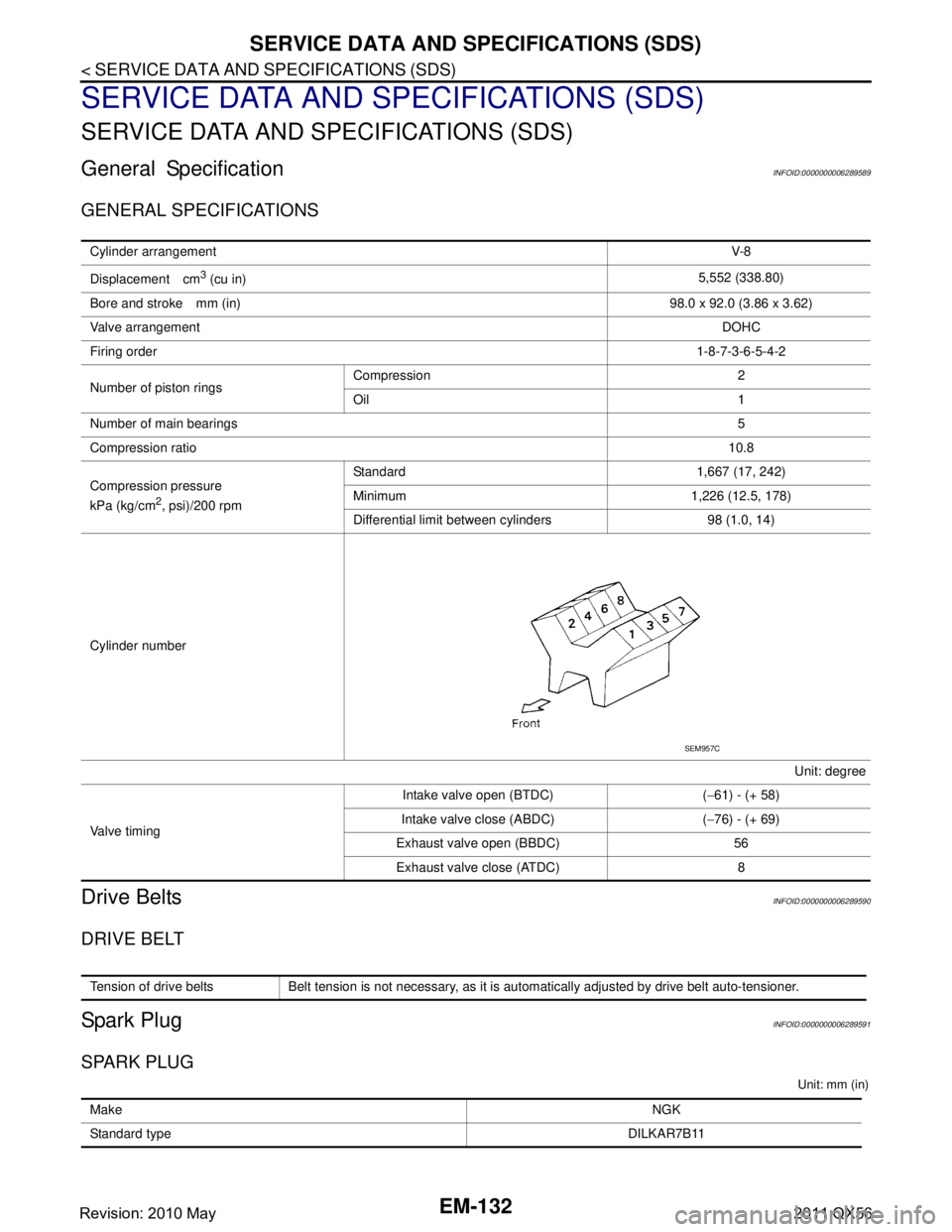
General SpecificationINFOID:0000000006289589
GENERAL SPECIFICATIONS
Drive BeltsINFOID:0000000006289590
DRIVE BELT
Spark PlugINFOID:0000000006289591
SPARK PLUG
Unit: mm (in)
Cylinder arrangementV-8
Displacement cm
3 (cu in) 5,552 (338.80)
Bore and stroke mm (in) 98.0 x 92.0 (3.86 x 3.62)
Valve arrangement DOHC
Firing order 1-8-7-3-6-5-4-2
Number of piston rings Compression 2
Oil 1
Number of main bearings 5
Compression ratio 10.8
Compression pressure
kPa (kg/cm
2, psi)/200 rpm Standard 1,667 (17, 242)
Minimum 1,226 (12.5, 178)
Differential limit between cylinders 98 (1.0, 14)
Cylinder number Unit: degree
Valve timing Intake valve open (BTDC) (
−61) - (+ 58)
Intake valve close (ABDC) ( −76) - (+ 69)
Exhaust valve open (BBDC) 56 Exhaust valve close (ATDC) 8
SEM957C
Tension of drive belts Belt tension is not necessary, as it is automatically adjusted by drive belt auto-tensioner.
Make NGK
Standard type DILKAR7B11
Revision: 2010 May2011 QX56
Page 2695 of 5598
SERVICE DATA AND SPECIFICATIONS (SDS)
EM-133
< SERVICE DATA AND SPECIFICATIONS (SDS)
C
D E
F
G H
I
J
K L
M A
EM
NP
O
Exhaust ManifoldINFOID:0000000006289592
EXHAUST MANIFOLD
Unit: mm (in)
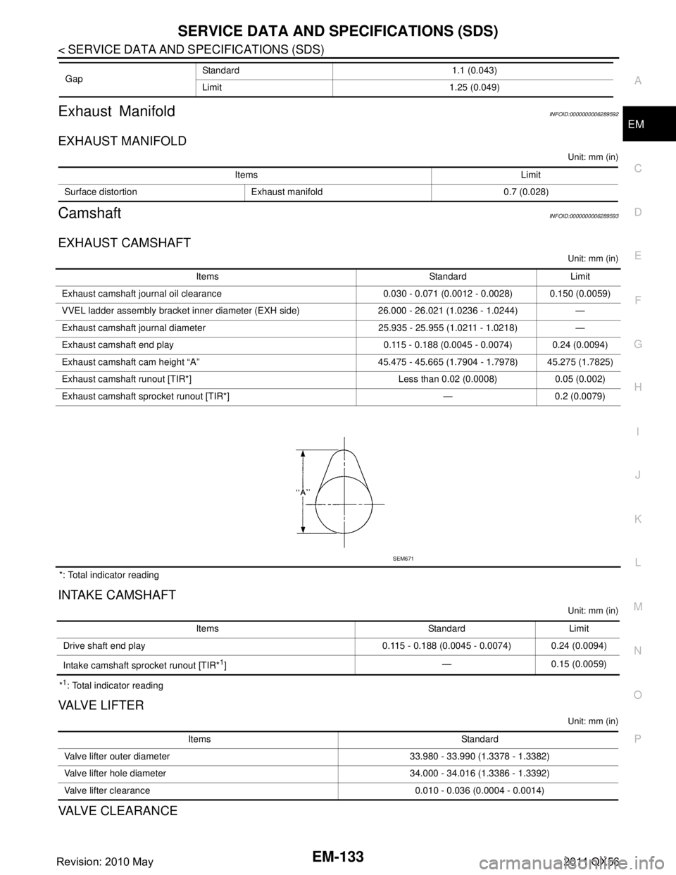
CamshaftINFOID:0000000006289593
EXHAUST CAMSHAFT
Unit: mm (in)
*: Total indicator reading
INTAKE CAMSHAFT
Unit: mm (in)
*1: Total indicator reading
VA LV E L I F T E R
Unit: mm (in)
VALVE CLEARANCE
Gap
Standard 1.1 (0.043)
Limit 1.25 (0.049)
Items Limit
Surface distortion Exhaust manifold 0.7 (0.028)
Items Standard Limit
Exhaust camshaft journal oil clearance 0.030 - 0.071 (0.0012 - 0.0028) 0.150 (0.0059)
VVEL ladder asse mbly bracket inner diameter (EXH side) 26.000 - 26.021 (1.0236 - 1.0244) —
Exhaust camshaft journal diameter 25.935 - 25.955 (1.0211 - 1.0218) —
Exhaust camshaft end play 0.115 - 0.188 (0.0045 - 0.0074) 0.24 (0.0094)
Exhaust camshaft cam height “A” 45.475 - 45.665 (1.7904 - 1.7978) 45.275 (1.7825)
Exhaust camshaft runout [TIR*] Less than 0.02 (0.0008) 0.05 (0.002)
Exhaust camshaft sprocket runout [TIR*] — 0.2 (0.0079)
SEM671
Items Standard Limit
Drive shaft end play 0.115 - 0.188 (0.0045 - 0.0074) 0.24 (0.0094)
Intake camshaft sprocket runout [TIR*
1] — 0.15 (0.0059)
Items Standard
Valve lifter outer diameter 33.980 - 33.990 (1.3378 - 1.3382)
Valve lifter hole diameter 34.000 - 34.016 (1.3386 - 1.3392)
Valve lifter clearance 0.010 - 0.036 (0.0004 - 0.0014)
Revision: 2010 May2011 QX56
Page 2696 of 5598
EM-134
< SERVICE DATA AND SPECIFICATIONS (SDS)
SERVICE DATA AND SPECIFICATIONS (SDS)
Unit: mm (in)
*: Approximately 80°C (176 °F)
AVAILABLE VALVE LIFTER
Unit: mm (in)
Items Cold Hot* (reference data)
Intake 0.26 - 0.34 (0.010 - 0.013) 0.304 - 0.416 (0.012 - 0.016)
Exhaust 0.29 - 0.37 (0.011 - 0.015) 0.308 - 0.432 (0.012 - 0.017)
Identification (stamped) mark Thickness 788P 7.88 (0.3102)
790P 7.90 (0.3110)
792P 7.92 (0.3118)
794P 7.94 (0.3126)
796P 7.96 (0.3134)
798P 7.98 (0.3142)
800P 8.00 (0.3150)
802P 8.02 (0.3157)
804P 8.04 (0.3165)
806P 8.06 (0.3173)
808P 8.08 (0.3181)
810P 8.10 (0.3189)
812P 8.12 (0.3197)
814P 8.14 (0.3205)
816P 8.16 (0.3213)
818P 8.18 (0.3220)
820P 8.20 (0.3228)
822P 8.22 (0.3236)
824P 8.24 (0.3244)
826P 8.26 (0.3252)
828P 8.28 (0.3260)
830P 8.30 (0.3268)
832P 8.32 (0.3276)
834P 8.34 (0.3283)
836P 8.36 (0.3291)
838P 8.38 (0.3299)
840P 8.40 (0.3307)
SEM758G
Revision: 2010 May2011 QX56
Page 2697 of 5598
SERVICE DATA AND SPECIFICATIONS (SDS)
EM-135
< SERVICE DATA AND SPECIFICATIONS (SDS)
C
D E
F
G H
I
J
K L
M A
EM
NP
O
Cylinder HeadINFOID:0000000006289594
CYLINDER HEAD
Unit: mm (in)
VALVE DIMENSIONS
Unit: mm (in)
VA LV E G U I D E
Items Standard Limit
Head surface distortion Less than 0.03 (0.0012) 0.1 (0.004)
Normal cylinder head height “H” 126.3 (4.97) —
PBIC0924E
Valve head diameter “D” Intake 36.6 - 36.9 (1.441 - 1.453)
Exhaust 31.2 - 31.5 (1.228 - 1.240)
Valve length “L” Intake 99.19 - 99.69 (3.9051 - 3.9248)
Exhaust 93.74 - 94.24 (3.6905 - 3.7102)
Valve stem diameter “d” Intake 5.965 - 5.980 (0.2348 - 0.2354)
Exhaust 5.955 - 5.970 (0.2344 - 0.2350)
Valve seat angle “ α” Intake
45°15 ′ - 45 °45 ′
Exhaust
Valve margin “T” Intake 1.1 (0.043)
Exhaust 1.3 (0.051)
Valve margin “T” limit 0.5 (0.020)
Valve stem end surface grinding limit 0.2 (0.008)
SEM188
Revision: 2010 May2011 QX56
Page 2698 of 5598
EM-136
< SERVICE DATA AND SPECIFICATIONS (SDS)
SERVICE DATA AND SPECIFICATIONS (SDS)
Unit: mm (in)
*: Parts settings are for exhaust side only
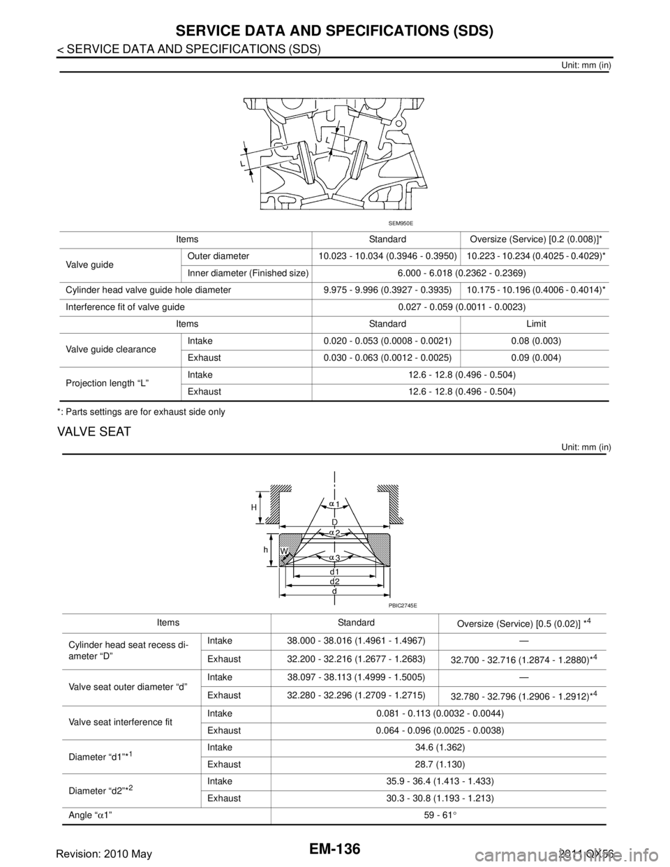
VALVE SEAT
Unit: mm (in)
Items Standard Oversize (Service) [0.2 (0.008)]*
Va l v e g u i d e Outer diameter 10.023 - 10.034 (0.3946 - 0.3950) 10.223 - 10.234 (0.4025 - 0.4029)*
Inner diameter (Finished size) 6.000 - 6.018 (0.2362 - 0.2369)
Cylinder head valve guide hole diameter 9.975 - 9.996 (0.3927 - 0.3935) 10.175 - 10.196 (0.4006 - 0.4014)*
Interference fit of valve guide 0.027 - 0.059 (0.0011 - 0.0023) Items Standard Limit
Valve guide clearance Intake 0.020 - 0.053 (0.0008 - 0.0021) 0.08 (0.003)
Exhaust 0.030 - 0.063 (0.0012 - 0.0025) 0.09 (0.004)
Projection length “L” Intake 12.6 - 12.8 (0.496 - 0.504)
Exhaust 12.6 - 12.8 (0.496 - 0.504)
SEM950E
Items Standard
Oversize (Service) [0.5 (0.02)] *4
Cylinder head seat recess di-
ameter “D”Intake 38.000 - 38.016 (1.4961 - 1.4967) —
Exhaust 32.200 - 32.216 (1.2677 - 1.2683)
32.700 - 32.716 (1.2874 - 1.2880)*
4
Valve seat outer diameter “d”Intake 38.097 - 38.113 (1.4999 - 1.5005) —
Exhaust 32.280 - 32.296 (1.2709 - 1.2715)
32.780 - 32.796 (1.2906 - 1.2912)*4
Valve seat interference fitIntake 0.081 - 0.113 (0.0032 - 0.0044)
Exhaust 0.064 - 0.096 (0.0025 - 0.0038)
Diameter “d1”*
1Intake 34.6 (1.362)
Exhaust 28.7 (1.130)
Diameter “d2”*
2Intake 35.9 - 36.4 (1.413 - 1.433)
Exhaust 30.3 - 30.8 (1.193 - 1.213)
Angle “ α1” 59 - 61°
PBIC2745E
Revision: 2010 May2011 QX56