2011 INFINITI QX56 service
[x] Cancel search: servicePage 2576 of 5598
EM-14
< BASIC INSPECTION >
CAMSHAFT VALVE CLEARANCE
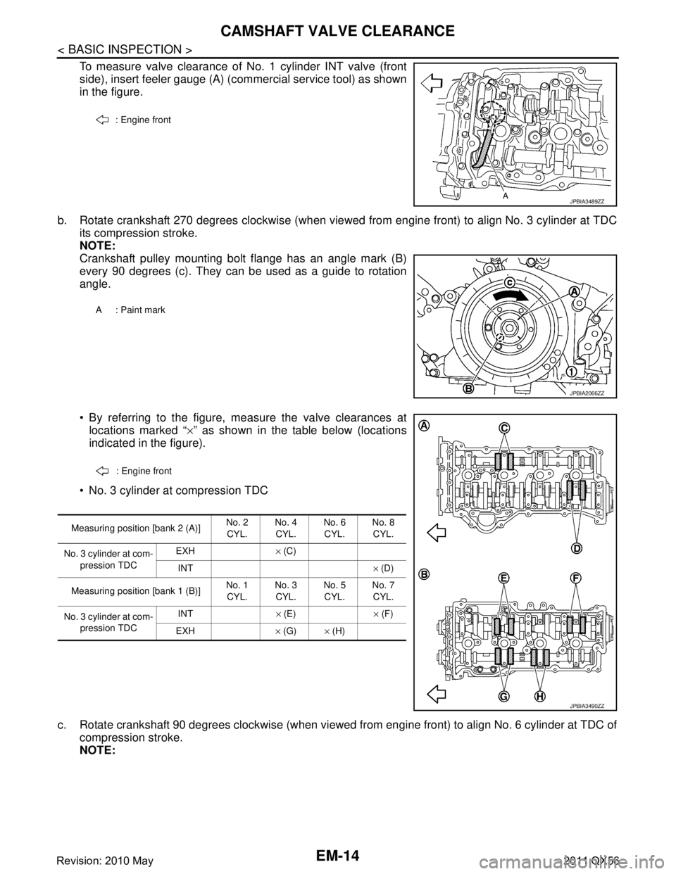
To measure valve clearance of No. 1 cylinder INT valve (front
side), insert feeler gauge (A) (commercial service tool) as shown
in the figure.
b. Rotate crankshaft 270 degrees clockwise (when viewed from engine front) to align No. 3 cylinder at TDC its compression stroke.
NOTE:
Crankshaft pulley mounting bolt flange has an angle mark (B)
every 90 degrees (c). They can be used as a guide to rotation
angle.
By referring to the figure, measure the valve clearances atlocations marked “ ×” as shown in the table below (locations
indicated in the figure).
No. 3 cylinder at compression TDC
c. Rotate crankshaft 90 degrees clockwise (when viewed from engine front) to align No. 6 cylinder at TDC of compression stroke.
NOTE:
: Engine front
JPBIA3489ZZ
A : Paint mark
JPBIA2066ZZ
: Engine front
Measuring position [bank 2 (A)] No. 2
CYL. No. 4
CYL. No. 6
CYL. No. 8
CYL.
No. 3 cylinder at com- pression TDC EXH
× (C)
INT × (D)
Measuring position [bank 1 (B)] No. 1
CYL. No. 3
CYL. No. 5
CYL. No. 7
CYL.
No. 3 cylinder at com- pression TDC INT
× (E) × (F)
EXH × (G) × (H)
JPBIA3490ZZ
Revision: 2010 May2011 QX56
Page 2578 of 5598
EM-16
< BASIC INSPECTION >
COMPRESSION PRESSURE
COMPRESSION PRESSURE
InspectionINFOID:0000000006289521
1. Warm up engine thoroughly. Then, stop it.
2. Release fuel pressure. Refer to EC-153, "
Work Procedure".
CAUTION:
If CONSULT-III is not used to release fuel pr essure leave the fuel pump fuse disconnected until
step 7.
3. Remove fuel pump fuse in IPDM E/R. NOTE:
For the fuse number, refer to EC-114, "
Wiring Diagram".
For the fuse arrangement, refer to PG-143, "
Fuse, Connector and Terminal Arrangement".
4. Remove engine cover. Refer to EM-25, "
Exploded View".
5. Remove ignition coil and spark plug from each cylinder. Refer to EM-29, "
Exploded View".
6. Connect engine tachometer (not required in use of CONSULT-III).
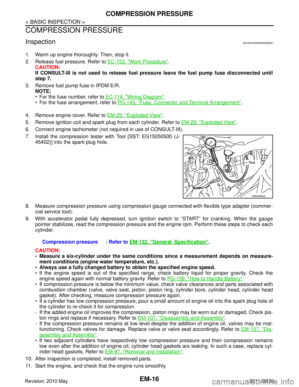
7. Install the compression tester with Tool [SST: EG15050500 (J- 45402)] into the spark plug hole.
8. Measure compression pressure using compressi on gauge connected with flexible type adapter (commer-
cial service tool).
9. With accelerator pedal fully depressed, turn ignition switch to “START” for cranking. When the gauge pointer stabilizes, read the compression pressure and the engine rpm. Perform these steps to check each
cylinder.
CAUTION:
Measure a six-cylinder under the same conditio ns since a measurement depends on measure-
ment conditions (engine water temperature, etc.).
Always use a fully changed battery to obtain the specified engine speed.
If the engine speed is out of the specified range, c heck battery liquid for proper gravity. Check the
engine speed again with normal battery gravity. Refer to PG-159, "
How to Handle Battery".
If compression pressure is below the minimum value, check valve clearances and parts associated with combustion chamber (valve, valve seat, piston, pi ston ring, cylinder bore, cylinder head, cylinder head
gasket). After checking, measure compression pressure again.
If a cylinder has low compression pressure, pour a small amount of engine oil into the spark plug hole of the cylinder to re-check it for compression.
- If the added engine oil improves the compression, pi ston rings may be worn out or damaged. Check pis-
ton rings and replace if necessary. Refer to EM-107, "
Disassembly and Assembly".
- If the compression pressure remains at low level despite the addition of engine oil, valves may be mal- functioning. Check valves for damage. Replace valve or valve seat accordingly. Refer to EM-107, "
Dis-
assembly and Assembly".
If two adjacent cylinders have respectively low co mpression pressure and their compression remains
low even after the addition of engine oil, cylinder head gaskets are leaking. In such a case, replace cyl-
inder head gaskets. Refer to EM-87, "
Removal and Installation".
10. After inspection is completed, install removed parts.
11. Start the engine, and check that the engine runs smoothly.
WBIA0605E
Compression pressure : Refer to EM-132, "GeneralSpecification".
Revision: 2010 May2011 QX56
Page 2596 of 5598

EM-34
< REMOVAL AND INSTALLATION >
ROCKER COVER
Loosen bolts in reverse order shown in the figure.
8. Remove rocker cover gasket from rocker cover.
9. Use scraper to remove all traces of liquid gasket from cylinder head & VVEL ladder assembly.
CAUTION:
Never scratch or damage the mating su rface when cleaning off old liquid gasket.
10. Remove PCV valve from rocker cover, if necessary.
11. Remove oil filler cap from rocker cover, if necessary.
INSTALLATION
1. Apply liquid gasket with the tube presser (commercial service tool) to VVEL ladder assembly (1).
Use Genuine RTV silicone seal ant or equivalent. Refer to
GI-22, "
Recommended Chemical Products and Sealants".
NOTE:
The figure shows an example of bank 1 side.
Apply liquid gasket on the front and rear side of engine first. [5 mm (0.20 in) + 5 mm (0.20 in) side as shown in the figure]
2. Install rocker cover gasket to rocker cover.
3. Install rocker cover. Check that rocker cover gasket does not drop fr om the installation groove of rocker cover.
A: Bank 2
B: Bank 1
: Engine front
JPBIA3481ZZ
A : Liquid gasket application point
F : End surface of VVEL ladder assembly
b : 4.0 mm (0.16 in)
c : 2.5 - 3.5 mm (0.098 - 0.138 in)
d : 5.0 mm (0.20 in)
e : 10.0 mm (0.39 in)
: Engine front
JPBIA3480ZZ
Revision: 2010 May2011 QX56
Page 2604 of 5598
EM-42
< REMOVAL AND INSTALLATION >
EXHAUST MANIFOLD AND THREE WAY CATALYST
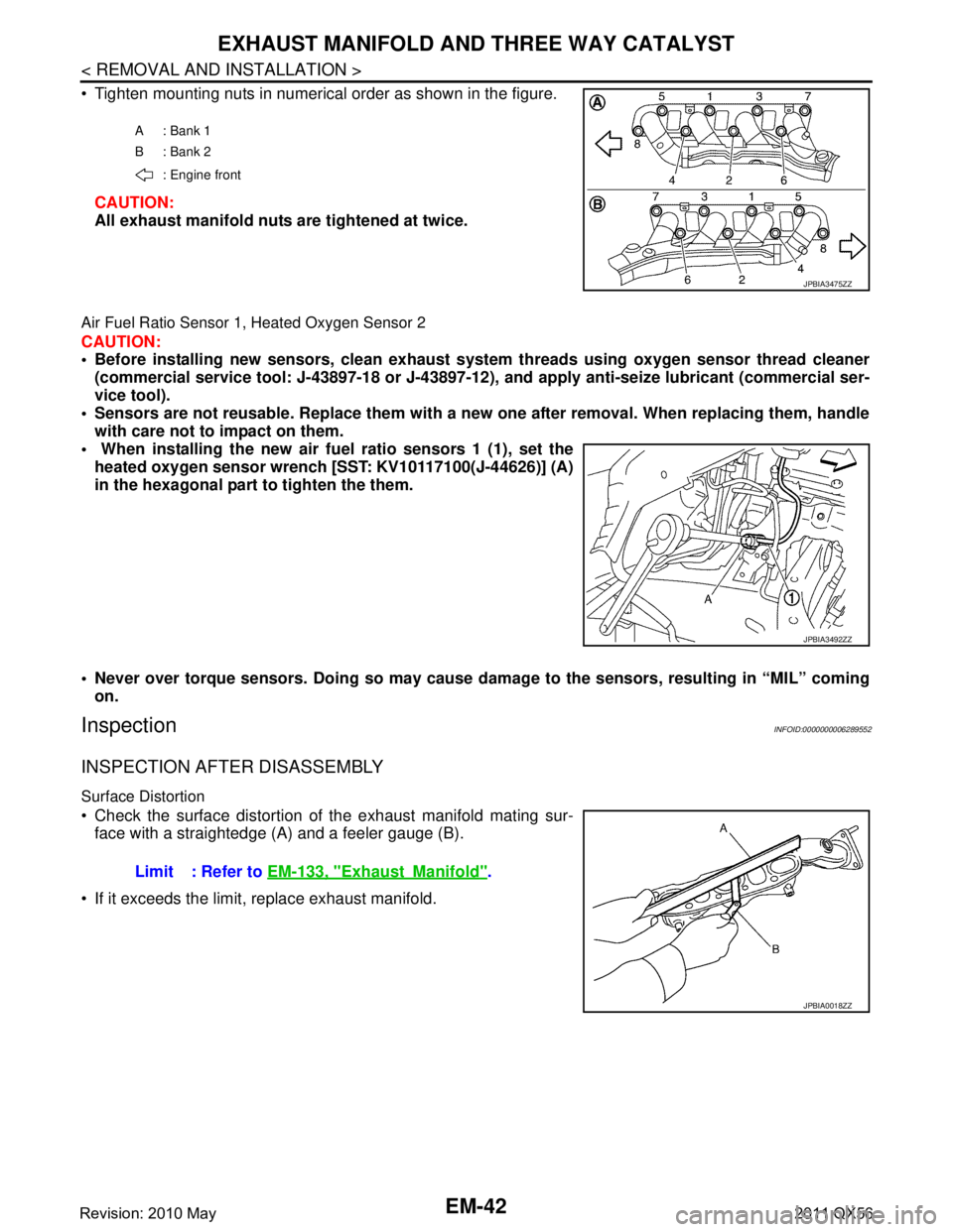
Tighten mounting nuts in numerical order as shown in the figure.CAUTION:
All exhaust manifold nuts are tightened at twice.
Air Fuel Ratio Sensor 1, Heated Oxygen Sensor 2
CAUTION:
Before installing new sensors, clean exhaust system threads usin g oxygen sensor thread cleaner
(commercial service tool: J-43897-18 or J-43897-12), and apply anti-seize lubricant (commercial ser-
vice tool).
Sensors are not reusable. Replace them with a ne w one after removal. When replacing them, handle
with care not to impact on them.
When installing the new air fu el ratio sensors 1 (1), set the
heated oxygen sensor wren ch [SST: KV10117100(J-44626)] (A)
in the hexagonal part to tighten the them.
Never over torque sensors. Doing so may cause da mage to the sensors, resulting in “MIL” coming
on.
InspectionINFOID:0000000006289552
INSPECTION AFTER DISASSEMBLY
Surface Distortion
Check the surface distortion of the exhaust manifold mating sur- face with a straightedge (A) and a feeler gauge (B).
If it exceeds the limit, replace exhaust manifold.
A: Bank 1
B: Bank 2 : Engine front
JPBIA3475ZZ
JPBIA3492ZZ
Limit : Refer to EM-133, "ExhaustManifold".
JPBIA0018ZZ
Revision: 2010 May2011 QX56
Page 2618 of 5598
EM-56
< REMOVAL AND INSTALLATION >
OIL PAN (LOWER) AND OIL STRAINER
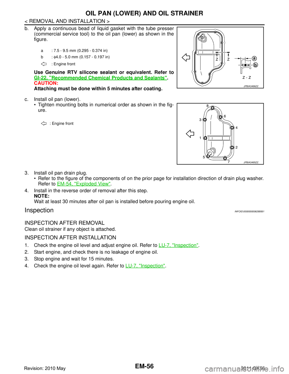
b. Apply a continuous bead of liquid gasket with the tube presser(commercial service tool) to the oil pan (lower) as shown in the
figure.
Use Genuine RTV silicone seal ant or equivalent. Refer to
GI-22, "
Recommended Chemical Products and Sealants".
CAUTION:
Attaching must be done with in 5 minutes after coating.
c. Install oil pan (lower). Tighten mounting bolts in numerical order as shown in the fig-ure.
3. Install oil pan drain plug. Refer to the figure of the components of on the prior page for installation direction of drain plug washer.Refer to EM-54, "
Exploded View".
4. Install in the reverse order of removal after this step. NOTE:
Wait at least 30 minutes after oil pan is installed before pouring engine oil.
InspectionINFOID:0000000006289561
INSPECTION AFTER REMOVAL
Clean oil strainer if any object is attached.
INSPECTION AFTER INSTALLATION
1. Check the engine oil level and adjust engine oil. Refer to LU-7, "Inspection".
2. Start engine, and check there is no leakage of engine oil.
3. Stop engine and wait for 15 minutes.
4. Check the engine oil level again. Refer to LU-7, "
Inspection".
a : 7.5 - 9.5 mm (0.295 - 0.374 in)
b: φ4.0 - 5.0 mm (0.157 - 0.197 in)
: Engine front
JPBIA3496ZZ
: Engine front
JPBIA3495ZZ
Revision: 2010 May2011 QX56
Page 2621 of 5598
OIL PAN (UPPER)EM-59
< REMOVAL AND INSTALLATION >
C
DE
F
G H
I
J
K L
M A
EM
NP
O
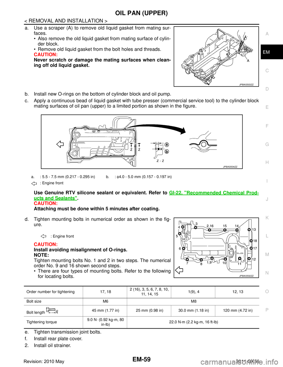
a. Use a scraper (A) to remove old liquid gasket from mating sur-
faces.
Also remove the old liquid gasket from mating surface of cylin-der block.
Remove old liquid gasket from the bolt holes and threads.
CAUTION:
Never scratch or damage th e mating surfaces when clean-
ing off old liquid gasket.
b. Install new O-rings on the bottom of cylinder block and oil pump.
c. Apply a continuous bead of liquid gasket with tube pre sser (commercial service tool) to the cylinder block
mating surfaces of oil pan (upper) to a limited portion as shown in the figure.
Use Genuine RTV silicone sealant or equivalent. Refer to GI-22, "
Recommended Chemical Prod-
ucts and Sealants".
CAUTION:
Attaching must be done with in 5 minutes after coating.
d. Tighten mounting bolts in numerical order as shown in the fig- ure.
CAUTION:
Install avoiding misal ignment of O-rings.
NOTE:
Tighten mounting bolts No. 1 and 2 in two steps. The numerical
order No. 9 and 16 shown second steps.
There are four types of mounting bolts. Refer to the following for locating bolts.
e. Tighten transmission joint bolts.
f. Install rear plate cover.
2. Install oil strainer.
JPBIA3503ZZ
a. : 5.5 - 7.5 mm (0.217 - 0.295 in) b. : φ4.0 - 5.0 mm (0.157 - 0.197 in)
: Engine front
JPBIA3504ZZ
: Engine front
JPBIA3502ZZ
Order number for tightening 17, 18 2 (16), 3, 5, 6, 7, 8, 10,
11, 14, 15 1(9), 4 12, 13
Bolt size M6 M8
Bolt length 45 mm (1.77 in) 25 mm (0.98 in) 30.0 mm (1.18 in) 120 mm (4.72 in)
Tightening torque 9.0 N· (0.92 kg-m, 80
in-lb) 22.0 N·m (2.2 kg-m, 16 ft-lb)
Revision: 2010 May2011 QX56
Page 2631 of 5598
TIMING CHAINEM-69
< REMOVAL AND INSTALLATION >
C
DE
F
G H
I
J
K L
M A
EM
NP
O
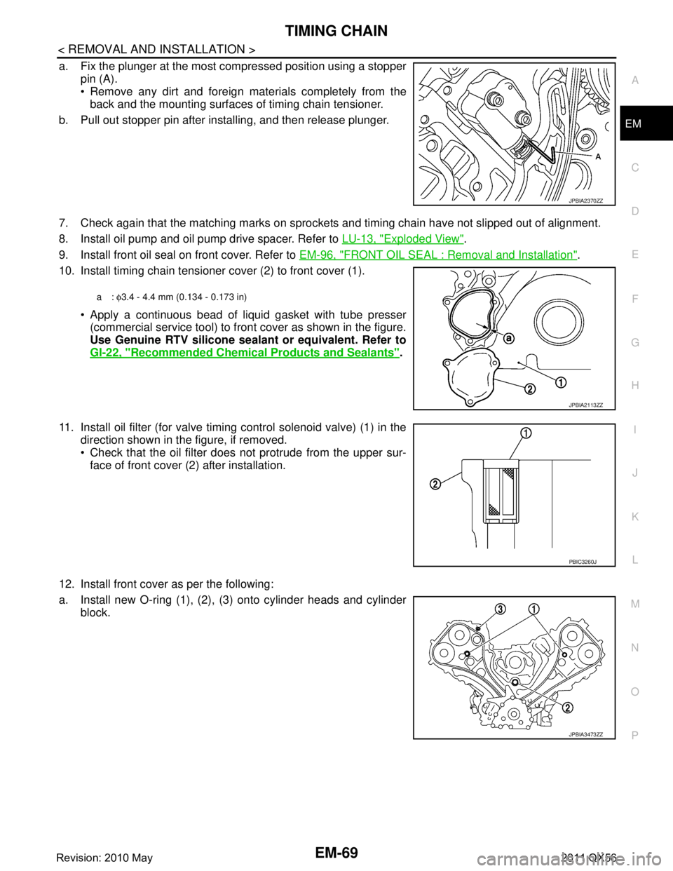
a. Fix the plunger at the most compressed position using a stopper
pin (A).
Remove any dirt and foreign materials completely from theback and the mounting surfaces of timing chain tensioner.
b. Pull out stopper pin after installing, and then release plunger.
7. Check again that the matching marks on sprockets and timing chain have not slipped out of alignment.
8. Install oil pump and oil pump drive spacer. Refer to LU-13, "
Exploded View".
9. Install front oil seal on front cover. Refer to EM-96, "
FRONT OIL SEAL : Removal and Installation".
10. Install timing chain tensioner cover (2) to front cover (1).
Apply a continuous bead of liquid gasket with tube presser(commercial service tool) to front cover as shown in the figure.
Use Genuine RTV silicone seal ant or equivalent. Refer to
GI-22, "
Recommended Chemical Products and Sealants".
11. Install oil filter (for valve timing control solenoid valve) (1) in the direction shown in the figure, if removed.
Check that the oil filter does not protrude from the upper sur-
face of front cover (2) after installation.
12. Install front cover as per the following:
a. Install new O-ring (1), (2), (3) onto cylinder heads and cylinder block.
JPBIA2370ZZ
a: φ3.4 - 4.4 mm (0.134 - 0.173 in)
JPBIA2113ZZ
PBIC3260J
JPBIA3473ZZ
Revision: 2010 May2011 QX56
Page 2632 of 5598
EM-70
< REMOVAL AND INSTALLATION >
TIMING CHAIN
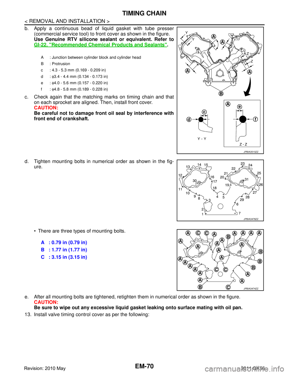
b. Apply a continuous bead of liquid gasket with tube presser(commercial service tool) to front cover as shown in the figure.
Use Genuine RTV silicone seal ant or equivalent. Refer to
GI-22, "
Recommended Chemical Products and Sealants".
c. Check again that the matching marks on timing chain and that on each sprocket are aligned. Then, install front cover.
CAUTION:
Be careful not to damage front oil seal by interference with
front end of crankshaft.
d. Tighten mounting bolts in numerical order as shown in the fig- ure.
There are three types of mounting bolts.
e. After all mounting bolts are tightened, retighten t hem in numerical order as shown in the figure.
CAUTION:
Be sure to wipe out any excessive liquid gasket leaking onto surface mating with oil pan.
13. Install valve timing control cover as per the following:
A : Junction between cylinder block and cylinder head
B : Protrusion
c : 4.3 - 5.3 mm (0.169 - 0.209 in)
d: φ3.4 - 4.4 mm (0.134 - 0.173 in)
e: φ4.0 - 5.6 mm (0.157 - 0.220 in)
f: φ4.8 - 5.8 mm (0.189 - 0.228 in)
JPBIA3510ZZ
JPBIA3478ZZ
A : 0.79 in (0.79 in)
B : 1.77 in (1.77 in)
C : 3.15 in (3.15 in)
JPBIA3474ZZ
Revision: 2010 May2011 QX56