2011 INFINITI QX56 light
[x] Cancel search: lightPage 3054 of 5598

REAR DOOR GLASSGW-25
< REMOVAL AND INSTALLATION >
C
DE
F
G H
I
J
L
M A
B
GW
N
O P
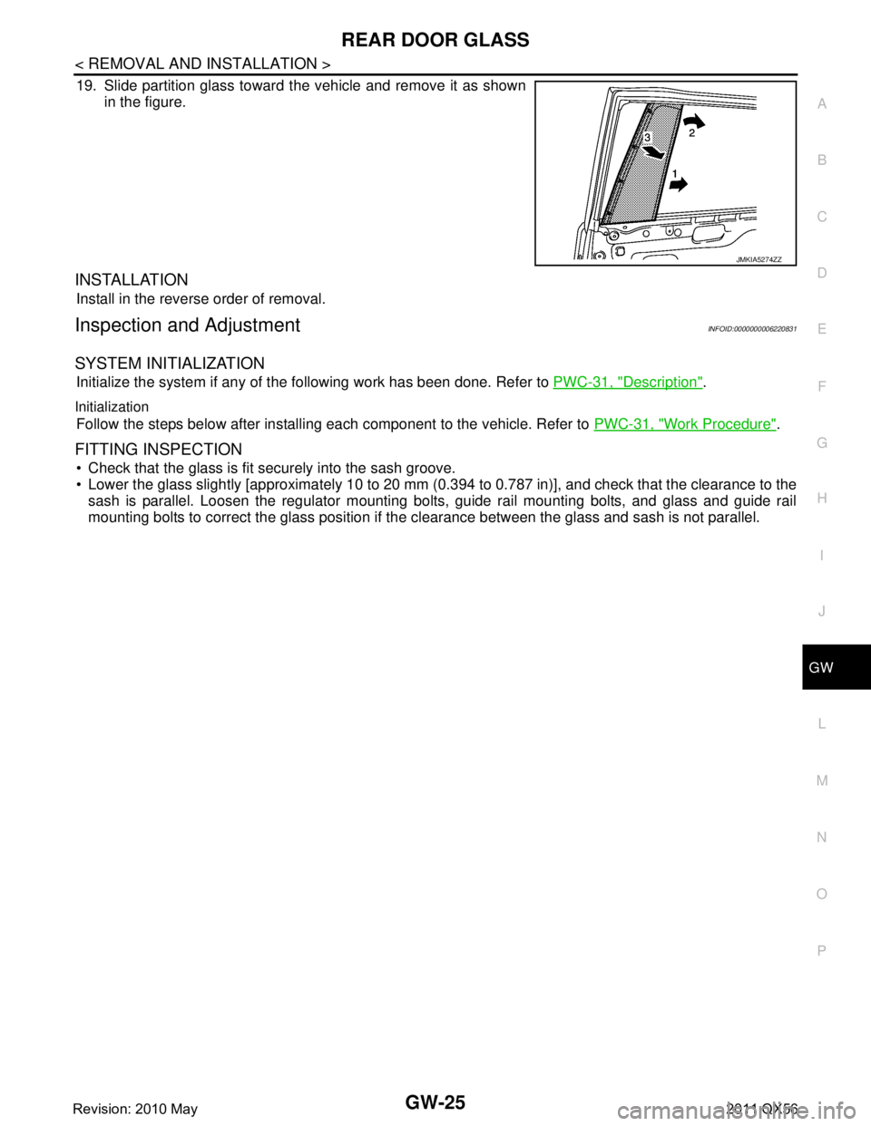
19. Slide partition glass toward the vehicle and remove it as shown in the figure.
INSTALLATION
Install in the reverse order of removal.
Inspection and AdjustmentINFOID:0000000006220831
SYSTEM INITIALIZATION
Initialize the system if any of t he following work has been done. Refer to PWC-31, "Description".
Initialization
Follow the steps below after installing each component to the vehicle. Refer to PWC-31, "Work Procedure".
FITTING INSPECTION
Check that the glass is fit securely into the sash groove.
Lower the glass slightly [approximately 10 to 20 mm (0.394 to 0.787 in)], and check that the clearance to the
sash is parallel. Loosen the regulator mounting bolts, guide rail mounting bolts, and glass and guide rail
mounting bolts to correct the glass position if the clearance between the glass and sash is not parallel.
JMKIA5274ZZ
Revision: 2010 May2011 QX56
Page 3056 of 5598

REAR REGULATORGW-27
< REMOVAL AND INSTALLATION >
C
DE
F
G H
I
J
L
M A
B
GW
N
O P
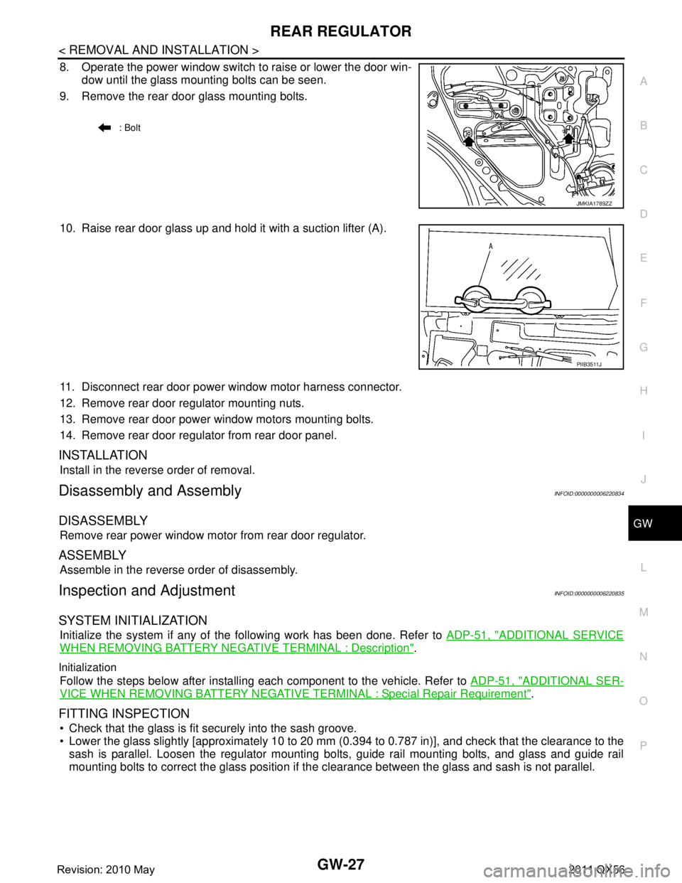
8. Operate the power window switch to raise or lower the door win- dow until the glass mounting bolts can be seen.
9. Remove the rear door glass mounting bolts.
10. Raise rear door glass up and hold it with a suction lifter (A).
11. Disconnect rear door power window motor harness connector.
12. Remove rear door regulator mounting nuts.
13. Remove rear door power window motors mounting bolts.
14. Remove rear door regulator from rear door panel.
INSTALLATION
Install in the reverse order of removal.
Disassembly and AssemblyINFOID:0000000006220834
DISASSEMBLY
Remove rear power window motor from rear door regulator.
ASSEMBLY
Assemble in the reverse order of disassembly.
Inspection and AdjustmentINFOID:0000000006220835
SYSTEM INITIALIZATION
Initialize the system if any of t he following work has been done. Refer to ADP-51, "ADDITIONAL SERVICE
WHEN REMOVING BATTERY NEGATIVE TERMINAL : Description".
Initialization
Follow the steps below after installing each component to the vehicle. Refer to ADP-51, "ADDITIONAL SER-
VICE WHEN REMOVING BATTERY NEGATIVE TERMINAL : Special Repair Requirement".
FITTING INSPECTION
Check that the glass is fit securely into the sash groove.
Lower the glass slightly [approximately 10 to 20 mm (0.394 to 0.787 in)], and check that the clearance to the
sash is parallel. Loosen the regulator mounting bolts, guide rail mounting bolts, and glass and guide rail
mounting bolts to correct the glass position if the clearance between the glass and sash is not parallel.
: Bolt
JMKIA1789ZZ
PIIB3511J
Revision: 2010 May2011 QX56
Page 3068 of 5598

HA-12
< PREPARATION >
PREPARATION
Commercial Service Tool
INFOID:0000000006276518
Sealant or/and LubricantINFOID:0000000006276143
HFC-134a (R-134a) Service Tool and Equipment
Never mix HFC-134a (R-134a) refrigerant and/or its s pecified lubricant with CFC-12 (R-12) refrigerant and/
or its lubricant.
Separate and non-interchangeable service equipment must be used for handling each type of refrigerant/ lubricant.
Refrigerant container fittings, service hose fittings and service equipment fittings (equipment which handles
refrigerant and/or lubricant) are different between CF C-12 (R-12) and HFC-134a (R-134a). This is to avoid
mixed use of the refrigerants/lubricant.
Never use adapters that convert one size fitting to another: refrigerant/lubricant contamination occurs and
compressor malfunction may result.
Tool name Description
Refrigerant identifier equipment Checking for refrigerant purity and
system contamination
Power tools For loosening bolts and nuts
RJIA0197E
PBIC0190E
Tool name Description
HFC-134a (R-134a) refrigerant Container color: Light blue
Container marking: HFC-134a (R-
134a)
Fitting size: Thread size
Large container 1/2
″-16 ACME
A/C System Oil Type S (DH-PS) Type: Polyalkylene glycol oil (PAG),
type S (DH-PS)
Application:
HFC-134a (R-134a) swash plate com-
pressors
Capacity: 40 m (1.4 Imp fl oz.)
S-NT196
S-NT197
Revision: 2010 May2011 QX56
Page 3075 of 5598

REFRIGERANTHA-19
< BASIC INSPECTION >
C
DE
F
G H
J
K L
M A
B
HA
N
O P
Never look directly into UV lamp light source.
NOTE:
For continuous operating time of UV lamp, fo llow the manufacturer operating instructions.
Illuminate piping joints from different angles us ing UV lamp and check that there is no leakage.
Use a mirror in area that is difficult to see to check refrigerant leakage.
Refrigerant leakage from evaporator can be detected by soaking cotton swab or a similar material with
drain hose water and illuminating it using UV lamp.
Dust, dirt, and packing materials adhesive used for condenser, evaporator, and other locations may flu- oresce. Be careful not to misidentify leakage.
5. Repair or replace parts where refrigerant leak age occurs and wipe off fluorescent leak detection dye.
NOTE:
Completely wipe off fluorescent leak detection dy e from gaps between parts, screw threads, and others
using a cotton swab or similar materials.
6. Use a UV lamp to check that no fluorescent leak detection dye remains after finishing work. WARNING:
Never look directly into UV lamp light source.
NOTE:
For continuous operating time of UV lamp, fo llow the manufacturer operating instructions.
Dust, dirt, and packing materials adhesive used for condenser, evaporator, and other locations may flu-
oresce. Be careful not to misidentify leakage.
CHECK REFRIGERANT LEAKAGE USIN G ELECTRICAL LEAK DETECTOR
WARNING:
Never check refrigerant leakage while the engine is running.
CAUTION:
Be careful of the following items so that in accurate checks or misidentifications are avoided.
Never allow refrigerant vapor, shop chemical vapors, cigarette smoke, or others around the vehicle.
Always check refrigerant leakage in a low air flow environment so that refrigerant may not disperse
when leakage occurs.
1. Stop the engine.
2. Connect recovery/recycling/recharging equipment or manifold gauge set to A/C service valve.
3. Check that A/C refrigerant pressure is 345 kPa (3.52 kg/cm
2, 50 psi) or more when temperature is 16 °C
(61 °F) or more. When pressure is lower than the spec ified value, recycle refrigerant completely and fill
refrigerant to the specified level.
NOTE:
Leakages may not be detected if A/C refri gerant pressure is 345 kPa (3.52 kg/cm
2, 50 psi) or less when
temperature is less than 16 °C (61 °F).
4. Clean area where refrigerant leakage check is per formed, and check refrigerant leakage along all sur-
faces of pipe connections and A/C system com ponents using electrical leak detector probe.
CAUTION:
Continue checking when a leakage is found. Always continue and complete checking along all
pipe connections and A/C system co mponents for additional leakage.
When a leakage is detected, clean leakage area using compressed air and check again.
When checking leakage of cooling unit inside, al ways clean inside of drain hose so that the
probe surface may not be exposed to water or dirt.
NOTE:
Always check leakage starting from high-pressure side and continue to low-pressure side.
When checking leakage of cooling unit inside, operate blower fan motor for 15 minutes or more at the maximum fan speed while the engine is stopped, and then insert electrical leak detector probe into drain
hose and hold for 10 minutes or more.
When disconnecting shut-off valve that is connected to A/C service valve, always evacuate remaining
refrigerant so that misidentification can be avoided.
5. Repair or replace parts where refrigerant leak age is detected. (Leakage is detected but leakage area is
unknown. GO TO 6.)
6. Start the engine and set A/C control in the following conditions. A/C switch ON
Air flow: VENT (ventilation)
Intake door position: Recirculation
Revision: 2010 May2011 QX56
Page 3152 of 5598
![INFINITI QX56 2011 Factory Service Manual
HAC-46
< ECU DIAGNOSIS INFORMATION >[AUTOMATIC AIR CONDITIONING]
A/C AUTO AMP.
*1: With ACCS (advanced climate control system)
*2: Perform self-diagnosis under sunshine. When performi
ng indoors, aim INFINITI QX56 2011 Factory Service Manual
HAC-46
< ECU DIAGNOSIS INFORMATION >[AUTOMATIC AIR CONDITIONING]
A/C AUTO AMP.
*1: With ACCS (advanced climate control system)
*2: Perform self-diagnosis under sunshine. When performi
ng indoors, aim](/manual-img/42/57033/w960_57033-3151.png)
HAC-46
< ECU DIAGNOSIS INFORMATION >[AUTOMATIC AIR CONDITIONING]
A/C AUTO AMP.
*1: With ACCS (advanced climate control system)
*2: Perform self-diagnosis under sunshine. When performi
ng indoors, aim a light (more than 60 W) at sunload
sensor, otherwise self-diagnosis indicates even though the sunload sensor is functioning normally.
NOTE:
If all of door motor DTCs (B2632, B2633, B2634, B2635, B2636, B2637, B2638, B2639, B263D, B263E,
B263F, B2654, B2655, B2661, B2662, B2663, B2664, B 2665, B2666, B2669, and B266A) are detected, check
door motor communication circuit. Refer to HAC-120, "
Diagnosis Procedure".
B262A*1GAS SENSOR HAC-83, "DTC Logic"
B262B*1GAS SENSORHAC-83, "DTC Logic"
B2630*2SUNLOAD SENSORHAC-86, "DTC Logic"
B2631*2SUNLOAD SENSORHAC-86, "DTC Logic"
B2632 DR AIRMIX DOOR MOT HAC-89, "DTC Logic"
B2633 DR AIRMIX DOOR MOTHAC-89, "DTC Logic"
B2634 PASS AIR MIX DOOR MOTHAC-91, "DTC Logic"
B2635 PASS AIR MIX DOOR MOTHAC-91, "DTC Logic"
B2636 DR VENT DOOR FAILHAC-93, "DTC Logic"
B2637 DR B/L DOOR FAILHAC-93, "DTC Logic"
B2638 DR D/F1 DOOR FAILHAC-93, "DTC Logic"
B2639 DR DEF DOOR FAILHAC-93, "DTC Logic"
B263D FRE DOOR FAIL HAC-95, "DTC Logic"
B263E 20P FRE DOOR FAILHAC-95, "DTC Logic"
B263F REC DOOR FAILHAC-95, "DTC Logic"
B2654 D/F2 DOOR FAILHAC-93, "DTC Logic"
B2655 B/L2 DOOR FAILHAC-93, "DTC Logic"
B2657*1GAS SENSOR CIRCUITHAC-83, "DTC Logic"
B2658*1GAS SENSOR CIRCUITHAC-83, "DTC Logic"
B2661 UPPER VENT DOOR MOT HAC-97, "DTC Logic"
B2662 UPPER VENT DOOR MOTHAC-97, "DTC Logic"
B2663 UPPER VENT DOOR MOTHAC-97, "DTC Logic"
B2664 REAR AIR MIX DOOR MOTHAC-99, "DTC Logic"
B2665 REAR AIR MIX DOOR MOTHAC-99, "DTC Logic"
B2666 REAR MODE DOOR MOTHAC-101, "DTC Logic"
B2667*2PASS SUNLOAD SENSORHAC-103, "DTC Logic"
B2668*2PASS SUNLOAD SENSORHAC-103, "DTC Logic"
B2669 REAR MODE DOOR MOT HAC-101, "DTC Logic"
B266A REAR MODE DOOR MOT HAC-101, "DTC Logic"
B266B REAR IN-VEHICLE SENHAC-106, "DTC Logic"
B266C REAR IN-VEHICLE SEN HAC-106, "DTC Logic"
B27B0 A/C AUTO AMP.HAC-109, "DTC Logic"
DTCItems
(CONSULT-III screen terms) Reference
Revision: 2010 May2011 QX56
Page 3192 of 5598
![INFINITI QX56 2011 Factory Service Manual
HAC-86
< DTC/CIRCUIT DIAGNOSIS >[AUTOMATIC AIR CONDITIONING]
B2630, B2631 SUNLOAD
SENSOR (DRIVER SIDE)
B2630, B2631 SUNLOAD SEN SOR (DRIVER SIDE)
DTC LogicINFOID:0000000006275920
DTC DETECTION LOGIC INFINITI QX56 2011 Factory Service Manual
HAC-86
< DTC/CIRCUIT DIAGNOSIS >[AUTOMATIC AIR CONDITIONING]
B2630, B2631 SUNLOAD
SENSOR (DRIVER SIDE)
B2630, B2631 SUNLOAD SEN SOR (DRIVER SIDE)
DTC LogicINFOID:0000000006275920
DTC DETECTION LOGIC](/manual-img/42/57033/w960_57033-3191.png)
HAC-86
< DTC/CIRCUIT DIAGNOSIS >[AUTOMATIC AIR CONDITIONING]
B2630, B2631 SUNLOAD
SENSOR (DRIVER SIDE)
B2630, B2631 SUNLOAD SEN SOR (DRIVER SIDE)
DTC LogicINFOID:0000000006275920
DTC DETECTION LOGIC
NOTE:
If DTC is displayed along with DTC U1000, first perform the trouble diagnosis for DTC U1000. Refer to HAC-
72, "DTC Logic".
If DTC is displayed along with DTC U1010, fi rst perform the trouble diagnosis for DTC U1010. HAC-73,
"DTC Logic".
Sunload sensor may register a malfunction when indoors, at dusk, or at other times when light is insufficient.
When performing the diagnosis indoors, use a lamp (60 W or more) that is pointed at the sunload sensor.
DTC CONFIRMATION PROCEDURE
1.PERFORM DTC CONFIRMATION PROCEDURE
With CONSULT-III
1. Turn ignition switch ON.
2. Select “Self Diagnostic Result” m ode of “HVAC” using CONSULT-III.
3. Check DTC.
Is DTC detected?
YES >> Refer to HAC-103, "Diagnosis Procedure".
NO >> INSPECTION END
Diagnosis ProcedureINFOID:0000000006275921
1.CHECK SUNLOAD SENSOR POWER SUPPLY
1. Turn ignition switch OFF.
2. Disconnect sunload sensor connector.
3. Turn ignition switch ON.
4. Check voltage between sunload sensor harness connector and ground.
Is the inspection result normal?
YES >> GO TO 2.
NO >> GO TO 4.
2.CHECK SUNLOAD SENSOR GROUND CIRCUIT
1. Turn ignition switch OFF.
2. Disconnect A/C auto amp. connector.
3. Check continuity between sunload sensor harne ss connector and A/C auto amp. harness connector.
DTCItems
(CONSULT-III screen terms) DTC detection condition Possible cause
B2630 SUNLOAD SENSOR Detected calorie at sunload sensor (driver side)
2832 W/m
2 (2436 kcal/m2·h) or more.
Sunload sensor
A/C auto amp.
Harness or connectors
[The sensor circui t (driver side) is
open or shorted.]
B2631
Detected calorie at sunload sensor (driver side)
64.7 W/m
2 (55.6 kcal/m2·h) or less.
+
−Voltage
(Approx.)
Sunload sensor
Connector Terminal M74 2 Ground 5 V
Sunload sensor —Continuity
Connector Terminal
M74 3 Ground Existed
Revision: 2010 May2011 QX56
Page 3209 of 5598
![INFINITI QX56 2011 Factory Service Manual
B2667, B2668 SUNLOAD SENSOR (PASSENGER SIDE)
HAC-103
< DTC/CIRCUIT DIAGNOSIS > [AUTOMATIC AIR CONDITIONING]
C
D
E
F
G H
J
K L
M A
B
HAC
N
O P
B2667, B2668 SUNLOAD SENS OR (PASSENGER SIDE)
DTC LogicIN INFINITI QX56 2011 Factory Service Manual
B2667, B2668 SUNLOAD SENSOR (PASSENGER SIDE)
HAC-103
< DTC/CIRCUIT DIAGNOSIS > [AUTOMATIC AIR CONDITIONING]
C
D
E
F
G H
J
K L
M A
B
HAC
N
O P
B2667, B2668 SUNLOAD SENS OR (PASSENGER SIDE)
DTC LogicIN](/manual-img/42/57033/w960_57033-3208.png)
B2667, B2668 SUNLOAD SENSOR (PASSENGER SIDE)
HAC-103
< DTC/CIRCUIT DIAGNOSIS > [AUTOMATIC AIR CONDITIONING]
C
D
E
F
G H
J
K L
M A
B
HAC
N
O P
B2667, B2668 SUNLOAD SENS OR (PASSENGER SIDE)
DTC LogicINFOID:0000000006275937
DTC DETECTION LOGIC
NOTE:
If DTC is displayed along with DTC U1000, first per form the trouble diagnosis for DTC U1000. Refer to HAC-
72, "DTC Logic".
If DTC is displayed along with DTC U1010, fi rst perform the trouble diagnosis for DTC U1010. HAC-73,
"DTC Logic".
Sunload sensor may register a malfunction when indoors, at dusk, or at other times when light is insufficient.
When performing the diagnosis indoors, use a lamp (60 W or more) that is pointed at the sunload sensor.
DTC CONFIRMATION PROCEDURE
1.PERFORM DTC CONFIRMATION PROCEDURE
With CONSULT-III
1. Turn ignition switch ON.
2. Select “Self Diagnostic Result” m ode of “HVAC” using CONSULT-III.
3. Check DTC.
Is DTC detected?
YES >> Refer to HAC-103, "Diagnosis Procedure".
NO >> INSPECTION END
Diagnosis ProcedureINFOID:0000000006275938
1.CHECK SUNLOAD SENSOR POWER SUPPLY
1. Turn ignition switch OFF.
2. Disconnect sunload sensor connector.
3. Turn ignition switch ON.
4. Check voltage between sunload sensor harness connector and ground.
Is the inspection result normal?
YES >> GO TO 2.
NO >> GO TO 4.
2.CHECK SUNLOAD SENSOR GROUND CIRCUIT
1. Turn ignition switch OFF.
2. Disconnect A/C auto amp. connector.
3. Check continuity between sunload sensor harnes s connector and A/C auto amp. harness connector.
DTCItems
(CONSULT-III screen terms) DTC detection condition Possible cause
B2667 PASS SUNLOAD SENSOR Detected calorie at sunload sensor (passenger
side) 2832 W/m
2 (2436 kcal/m2·h) or more.
Sunload sensor
A/C auto amp.
Harness or connectors
[The sensor circuit (passenger
side) is open or shorted.]
B2668
Detected calorie at sunload sensor (passenger
side) 64.7 W/m
2 (55.6 kcal/m2·h) or less.
+
−Vol tag e
(Approx.)
Sunload sensor
Connector Terminal M74 1 Ground 5 V
Sunload sensor —Continuity
Connector Terminal
M74 3 Ground Existed
Revision: 2010 May2011 QX56
Page 3246 of 5598
![INFINITI QX56 2011 Factory Service Manual
HAC-140
< SYMPTOM DIAGNOSIS >[AUTOMATIC AIR CONDITIONING]
INSUFFICIENT HEATING
INSUFFICIENT HEATING
FRONT AIR CONDITIONER
FRONT AIR CONDITIONER : DescriptionINFOID:0000000006275990
Symptom Insuffici INFINITI QX56 2011 Factory Service Manual
HAC-140
< SYMPTOM DIAGNOSIS >[AUTOMATIC AIR CONDITIONING]
INSUFFICIENT HEATING
INSUFFICIENT HEATING
FRONT AIR CONDITIONER
FRONT AIR CONDITIONER : DescriptionINFOID:0000000006275990
Symptom Insuffici](/manual-img/42/57033/w960_57033-3245.png)
HAC-140
< SYMPTOM DIAGNOSIS >[AUTOMATIC AIR CONDITIONING]
INSUFFICIENT HEATING
INSUFFICIENT HEATING
FRONT AIR CONDITIONER
FRONT AIR CONDITIONER : DescriptionINFOID:0000000006275990
Symptom Insufficient heating
No warm air comes out. (Air flow volume is normal.)
FRONT AIR CONDITIONER
: Diagnosis ProcedureINFOID:0000000006275991
NOTE:
Perform self-diagnoses with on board diagnosis and CO NSULT-III before performing symptom diagnosis. If
DTC is detected, perform the corresponding diagnosis.
1.CHECK COOLING SYSTEM
1. Check engine coolant level and check leakage. Refer to CO-8, "
Inspection".
2. Check reservoir tank cap. Refer to CO-11, "
RESERVOIR TANK CAP : Inspection".
3. Check water flow sounds of the engine coolant. Refer to CO-9, "
Refilling".
Is the inspection result normal?
YES >> GO TO 2.
NO >> Refill engine coolant and repair or repl ace parts depending on the inspection results.
2.CHECK HEATER HOSE
Check installation of heater hose by visually or touching.
Is the inspection result normal?
YES >> GO TO 3.
NO >> Repair or replace parts depending on the inspection results.
3.CHECK FRONT HEATER CORE
1. Check temperature of inlet hose and outlet hose of front heater core.
2. Check that inlet side of front heater core is hot and t he outlet side is slightly lower than/almost equal to the
inlet side.
CAUTION:
Always perform the temperature in spection in a short period of time because the engine coolant
temperature is very hot.
Is the inspection result normal?
YES >> GO TO 4.
NO >> Replace front heater core. Refer to HA-44, "
HEATER CORE : Removal and Installation".
4.CHECK AIR LEAKAGE FROM EACH DUCT
Check duct and nozzle, etc. of front air conditioning system for air leakage.
Is the inspection result normal?
YES >> GO TO 5.
NO >> Repair or replace parts depending on the inspection results.
5.CHECK SETTING OF TEMPERATURE SETTING TRIMMER (FRONT)
1. Check setting value of temperature setting trimmer (front). Refer to HAC-68, "
FRONT AUTOMATIC AIR
CONDITIONING SYSTEM : Temperature Setting Trimmer (Front)".
2. Check that temperature setting trimmer (front) is set to “ − direction”.
NOTE:
The control temperature can be set by t he temperature setting trimmer (front).
3. Set difference between the set temperature and control temperature to “0”.
Are the symptoms solved?
YES >> INSPECTION END
NO >> Replace A/C auto amp.. Refer to HAC-146, "
Removal and Installation".
REAR AIR CONDITIONER
Revision: 2010 May2011 QX56