2011 INFINITI QX56 wheel
[x] Cancel search: wheelPage 488 of 5598

BR-18
< PERIODIC MAINTENANCE >
REAR DISC BRAKE
REAR DISC BRAKE
BRAKE PAD
BRAKE PAD : Inspection and AdjustmentINFOID:0000000006222470
INSPECTION
Check the thickness of brake pad from the inspection hole (A) on
brake caliper assembly. Check use a scale if necessary.
ADJUSTMENT
CAUTION:
Burnish contact surfaces between pads according to the following procedure after refinishing or
replacing brake pads, or if a soft pedal occurs at very low mileage.
Be careful of vehicle speed because the brake does not operate firmly/securely until pads and disc
rotor are securely fitted.
Only perform this procedure under safe road and traffic conditions. Use extreme caution.
1. Drive vehicle on straight, flat road.
2. Depress brake pedal with the power to stop vehicl e within 3 to 5 seconds until the vehicle stops.
3. Drive without depressing brake for a few minutes to cool the brake.
4. Repeat steps 1 to 3 until pad and disc rotor are securely fitted.
DISC ROTOR
DISC ROTOR : Inspec tion and AdjustmentINFOID:0000000006222471
INSPECTION
Appearance
Check surface of disc rotor for uneven wear, cracks, and serious damage. Replace it if necessary. Refer to
RAX-7, "
Removal and Installation".
Runout
1. Fix the disc rotor to the wheel hub and bearing assembly with wheel nuts (2 points at least).
2. Check the wheel bearing axial end play before the inspection. Refer to RAX-5, "
Inspection".
3. Inspect the runout with a dial indicator to measure at 10 mm (0.39 in) inside the disc edge.
4. Find the installation position that has a minimum runout by shift-
ing the disc rotor-to-wheel hub and bearing assembly installation
position by one hole at a time if the runout exceeds the limit
value.
5. Refinish the disc rotor if the runout is outside the limit even after performing the above operation. [When refinishing, use the Pro-
Cut PEM On-Car brake Lathe (Tool No. 38-PFM90.5) or equiva-
lent.]
CAUTION:
Check in advance that the thickn ess of the disc rotor is wear thickness + 0.3 mm (0.012 in) or
more. Wear thickness : Refer to
BR-47, "
Rear Disc Brake".
JPFIA0720ZZ
Runout : Refer to BR-47, "Rear Disc Brake".
JPFIA0721ZZ
Revision: 2010 May2011 QX56
Page 494 of 5598
BR-24
< REMOVAL AND INSTALLATION >
BRAKE PIPING
Never reuse the copper washer.
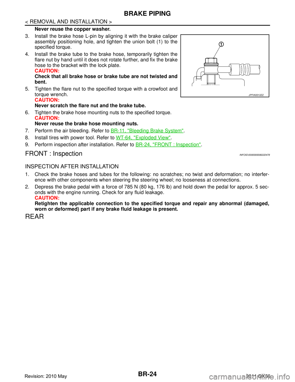
3. Install the brake hose L-pin by aligning it with the brake caliper assembly positioning hole, and tighten the union bolt (1) to the
specified torque.
4. Install the brake tube to the brake hose, temporarily tighten the flare nut by hand until it does not rotate further, and fix the brake
hose to the bracket with the lock plate.
CAUTION:
Check that all brake hose or brake tube are not twisted and
bent.
5. Tighten the flare nut to the specified torque with a crowfoot and torque wrench.
CAUTION:
Never scratch the flare nut and the brake tube.
6. Tighten the brake hose mounting nuts to the specified torque. CAUTION:
Never reuse the brake hose mounting nuts.
7. Perform the air bleeding. Refer to BR-11, "
Bleeding Brake System".
8. Install tires with power tool. Refer to WT-64, "
Exploded View".
9. Perform inspection after installation. Refer to BR-24, "
FRONT : Inspection".
FRONT : InspectionINFOID:0000000006222478
INSPECTION AFTER INSTALLATION
1. Check the brake hoses and tubes for the following: no scratches; no twist and deformation; no interfer-
ence with other components when steering the steering wheel; no looseness at connections.
2. Depress the brake pedal with a force of 785 N (80 kg, 176 lb) and hold down the pedal for approx. 5 sec- onds with the engine running. Check for any fluid leakage.
CAUTION:
Retighten the applicable connection to the specified torque and repair any abnormal (damaged,
worn or deformed) part if any brake fluid leakage is present.
REAR
JPFIA0012ZZ
Revision: 2010 May2011 QX56
Page 496 of 5598
BR-26
< REMOVAL AND INSTALLATION >
BRAKE PIPING
REAR : Removal and Installation
INFOID:0000000006222481
REMOVAL
CAUTION:
If the brake fluid adheres to the brake caliper assembly and disc rotor, quickly wipe it off.
Never spill or splash brake fluid on painted surfaces. Brake fluid may seriously damage paint. Wipe it
off immediately and wash with wate r if it gets on a painted surface.
Never depress the brake pedal. Brake fluid may spl ash while removing the brake hose or brake tube.
1. Remove tires with power tool.
2. Drain brake fluid. Refer to BR-10, "
Draining".
3. Loosen the flare nut with a flare nut wrench and separate the brake tube and the brake hose. CAUTION:
Never scratch the flare nut and the brake tube.
Never bend sharply, twist or strongly pull out the brake hose or brake tube.
Cover open end of brake hose or brake tube wh en disconnecting to prevent entrance of dirt.
4. Remove the union bolt and copper washers, and remove the brake hose from the brake caliper assembly.
5. Remove the lock plate and remove the brake hose.
INSTALLATION
CAUTION:
If the brake fluid adheres to the brake caliper assembly and disc rotor, quickly wipe it off.
Never spill or splash brake fluid on painted surfaces. Brake fluid may seriously damage paint. Wipe it
off immediately and wash with wate r if it gets on a painted surface.
Never depress the brake pedal. Brake fluid may spl ash while removing the brake hose or brake tube.
1. Assemble the union bolt and the copper washers to the brake hose. CAUTION:
Never reuse the copper washer.
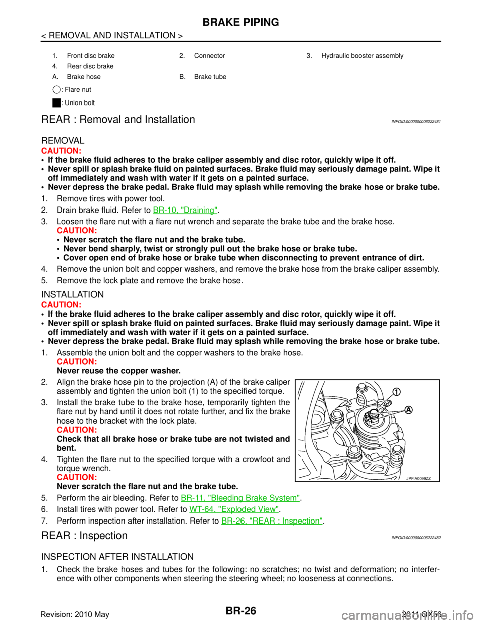
2. Align the brake hose pin to the projection (A) of the brake caliper
assembly and tighten the union bolt (1) to the specified torque.
3. Install the brake tube to the brake hose, temporarily tighten the flare nut by hand until it does not rotate further, and fix the brake
hose to the bracket with the lock plate.
CAUTION:
Check that all brake hose or brake tube are not twisted and
bent.
4. Tighten the flare nut to the specified torque with a crowfoot and torque wrench.
CAUTION:
Never scratch the flare nut and the brake tube.
5. Perform the air bleeding. Refer to BR-11, "
Bleeding Brake System".
6. Install tires with power tool. Refer to WT-64, "
Exploded View".
7. Perform inspection after installation. Refer to BR-26, "
REAR : Inspection".
REAR : InspectionINFOID:0000000006222482
INSPECTION AFTER INSTALLATION
1. Check the brake hoses and tubes for the following: no scratches; no twist and deformation; no interfer-
ence with other components when steering the steering wheel; no looseness at connections.
1. Front disc brake 2. Connector 3. Hydraulic booster assembly
4. Rear disc brake
A. Brake hose B. Brake tube
: Flare nut
: Union bolt
JPFIA0099ZZ
Revision: 2010 May2011 QX56
Page 507 of 5598

FRONT DISC BRAKEBR-37
< REMOVAL AND INSTALLATION >
C
DE
G H
I
J
K L
M A
B
BR
N
O P
BRAKE CALIPER ASSEMBLY : Removal and InstallationINFOID:0000000006222492
REMOVAL
WARNING:
Clean any dust from the brake caliper assembly an d brake pads with a vacuum dust collector. Never
blow with compressed air.
CAUTION:
Never spill or splash brake fluid on painted surfaces. Brake fluid may seriously damage paint. Wipe it
off immediately and wash with wate r if it gets on a painted surface.
Never depress the brake pedal. Brake fluid m ay splash while removing the brake hose.
If the brake fluid or grease adheres to the brake cal iper assembly and disc rotor, quickly wipe it off.
1. Remove tires with power tool.
2. Fix the disc rotor using wheel nuts.
3. Drain brake fluid. Refer to BR-10, "
Draining".
4. Separate brake hose from brake caliper assembly. Refer to BR-23, "
FRONT : Removal and Installation".
5. Remove torque member mounting bolts, and remove brake caliper assembly. CAUTION:
Never drop brake pad and brake caliper assembly.
6. Remove disc rotor. Refer to FA X - 8 , "
Removal and Installation" (2WD), FAX-18, "Removal and Installation"
(AWD).
INSTALLATION
WARNING:
Clean any dust from the brake caliper assembly an d brake pads with a vacuum dust collector. Never
blow with compressed air.
CAUTION:
Never spill or splash brake fluid on painted surfaces. Brake fluid may seriously damage paint. Wipe it
off immediately and wash with wate r if it gets on a painted surface.
Never depress the brake pedal. Brake fluid m ay splash while removing the brake hose.
If the brake fluid or grease adheres to the brake cal iper assembly and disc rotor, quickly wipe it off.
1. Torque member 2. Sliding pin boot 3. Sliding pin
4. Piston boot 5. Piston 6. Piston seal
7. Cylinder body 8. Bleeder valve 9. Cap
: Apply rubber grease.
: Apply brake fluid.
Refer to GI-4, "
Components" for symbols not described on the above.
JPFIA0800GB
Revision: 2010 May2011 QX56
Page 514 of 5598
BR-44
< REMOVAL AND INSTALLATION >
REAR DISC BRAKE
CAUTION:
Never spill or splash brake fluid on painted surfaces. Brake fluid may seriously damage paint. Wipe it
off immediately and wash with wate r if it gets on a painted surface.
Never depress the brake pedal. Brake fluid may splash while removing the brake hose.
If the brake fluid or grease adheres to the brake calip er assembly and disc rotor, quickly wipe it off.
1. Remove tires with power tool.
2. Fix the disc rotor using wheel nuts.
3. Drain brake fluid. Refer to BR-10, "
Draining".
4. Separate brake hose from brake caliper assembly. Refer to BR-26, "
REAR : Removal and Installation".
5. Remove torque member mounting bolts, and remove brake caliper assembly. CAUTION:
Never drop brake pad and caliper assembly.
6. Remove disc rotor. Refer to RAX-7, "
Removal and Installation".
INSTALLATION
WARNING:
Clean any dust from the brake caliper assembly an d brake pads with a vacuum dust collector. Never
blow with compressed air.
CAUTION:
Never spill or splash brake fluid on painted surfaces. Brake fluid may seriously damage paint. Wipe it
off immediately and wash with wate r if it gets on a painted surface.
Never depress the brake pedal. Brake fluid may splash while removing the brake hose.
If the brake fluid or grease adheres to the brake calip er assembly and disc rotor, quickly wipe it off.
1. Install disc rotor. Refer to RAX-7, "
Removal and Installation".
2. Install the brake caliper assembly to the axle hous ing and tighten the torque member mounting bolts to the
specified torque.
CAUTION:
Never spill or splash any grease and moisture on the brake caliper assembly mounting face,
threads, mounting bolts. Wipe out any grease and moisture.
3. Install brake hose to brake caliper assembly. Refer to BR-26, "
REAR : Removal and Installation".
4. Perform the air bleeding. Refer to BR-11, "
Bleeding Brake System".
5. Check a drag of rear disc brake. If any drag is found, refer to BR-45, "
BRAKE CALIPER ASSEMBLY :
Inspection".
6. Install tires with power tool. Refer to WT-64, "
Exploded View".
BRAKE CALIPER ASSEMBLY : Disassembly and AssemblyINFOID:0000000006222500
DISASSEMBLY
NOTE:
Never remove the torque member, brake pads and pad retainers when disassembling and assembling the cyl-
inder body.
1. Remove the sliding pin bolt, and remove the cylinder body from the torque member.
CAUTION:
Fix the brake pad at suitable tape so that the brake pad will not drop.
2. Remove sliding pin boots from torque member.
3. Remove bushing from sliding pin bolt.
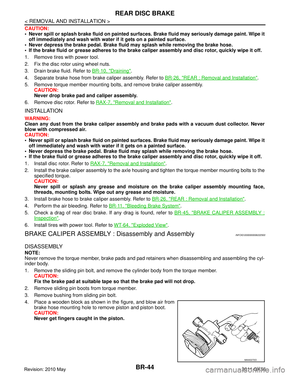
4. Place a wooden block as shown in the figure, and blow air from brake hose mounting hole to remove piston and piston boot.
CAUTION:
Never get fingers caught in the piston.
MAA0272D
Revision: 2010 May2011 QX56
Page 518 of 5598
BRC-1
BRAKES
C
DE
G H
I
J
K L
M
SECTION BRC
A
B
BRC
N
O P
CONTENTS
BRAKE CONTROL SYSTEM
WITH VDC
PRECAUTION ................ ...............................
5
PRECAUTIONS .............................................. .....5
Precaution for Supplemental Restraint System
(SRS) "AIR BAG" and "SEAT BELT PRE-TEN-
SIONER" ............................................................. ......
5
Precaution Necessary for Steering Wheel Rota-
tion after Battery Disconnect .....................................
5
Precaution for Procedure without Cowl Top Cover ......6
Precaution for Brake System ....................................6
Precaution for Brake Control System ........................6
Precaution for Harness Repair ..................................7
PREPARATION ............................................9
PREPARATION .............................................. .....9
Commercial Service Tools .................................. ......9
SYSTEM DESCRIPTION .............................10
COMPONENT PARTS ................................... ....10
Component Parts Location .................................. ....10
Component Description ...........................................13
ABS Actuator and Electric Unit (Control Unit) .........14
Wheel Sensor and Sensor Rotor ............................14
Stop Lamp Switch ...................................................15
Steering Angle Sensor ............................................15
Yaw Rate/Side/Decel G sensor ...............................15
Brake Fluid Level Switch .........................................15
Parking Brake Switch ..............................................15
VDC OFF Switch .....................................................15
SYSTEM .............................................................16
System Description ............................................. ....16
Fail-safe ..................................................................25
Protection Function .................................................28
VDC FUNCTION .................................................... ....28
VDC FUNCTION : System Description ...................28
TCS FUNCTION ..................................................... ....31
TCS FUNCTION : System Description ....................31
ABS FUNCTION .................................................... ....32
ABS FUNCTION : System Description ....................33
EBD FUNCTION .................................................... ....34
EBD FUNCTION : System Description ....................34
HILL START ASSIST FUNCTION ......................... ....36
hill start assist FUNCTION : System Description ....36
BRAKE LIMITED SLIP DIFFERENTIAL (BLSD)
FUNCTION ............................................................. ....
37
BRAKE LIMITED SLIP DIFFERENTIAL (BLSD)
FUNCTION : System Description ............................
37
DIAGNOSIS SYSTEM [ABS ACTUATOR
AND ELECTRIC UNIT (CONTROL UNIT)] .......
40
CONSULT-III Function ............................................40
ECU DIAGNOSIS INFORMATION ..............45
ABS ACTUATOR AND ELECTRIC UNIT
(CONTROL UNIT) .............................................
45
Reference Value .................................................. ....45
Fail-safe ...................................................................47
Protection Function ..................................................50
DTC Inspection Priority Chart ..................................50
DTC Index ...............................................................51
WIRING DIAGRAM ......................................53
BRAKE CONTROL SYSTEM ...........................53
Wiring Diagram .................................................... ....53
BASIC INSPECTION ...................................60
DIAGNOSIS AND REPAIR WORK FLOW .......60
Work Flow ............................................................ ....60
Diagnostic Work Sheet ............................................61
Revision: 2010 May2011 QX56
Page 519 of 5598

BRC-2
ADDITIONAL SERVICE WHEN REPLACING
ABS ACTUATOR AND ELECTRIC UNIT
(CONTROL UNIT) ..............................................
63
Description ........................................................... ...63
ADJUSTMENT OF STEERING ANGLE SEN-
SOR NEUTRAL POSITION ...............................
64
Description ........................................................... ...64
Work Procedure ......................................................64
CALIBRATION OF DECEL G SENSOR ...........66
Description ........................................................... ...66
Work Procedure ......................................................66
DTC/CIRCUIT DIAGNOSIS ...................... ...68
C1101, C1102, C1103, C1104 WHEEL SEN-
SOR ................................................................. ...
68
DTC Logic ............................................................ ...68
Diagnosis Procedure ..............................................68
C1105, C1106, C1107, C1108 WHEEL SEN-
SOR ....................................................................
70
DTC Logic ............................................................ ...70
Diagnosis Procedure ..............................................70
C1109 POWER AND GROUND SYSTEM .........72
Description ........................................................... ...72
DTC Logic ...............................................................72
Diagnosis Procedure ..............................................72
C1111 PUMP MOTOR .......................................75
DTC Logic ............................................................ ...75
Diagnosis Procedure ..............................................75
C1115 WHEEL SENSOR ...................................77
DTC Logic ............................................................ ...77
Diagnosis Procedure ..............................................77
C1116 STOP LAMP SWITCH ............................79
DTC Logic ............................................................ ...79
Diagnosis Procedure ..............................................79
Component Inspection (Stop lamp Switch) ............85
Component Inspection (Stop Lamp Relay) .............86
C1118 TRANSFER CONTROL UNIT ................87
DTC Logic ............................................................ ...87
Diagnosis Procedure ..............................................87
C1120, C1122, C1124, C1126 ABS IN VALVE
SYSTEM .......................................................... ...
88
DTC Logic ............................................................ ...88
Diagnosis Procedure ..............................................88
C1121, C1123, C1125, C1127 ABS OUT
VALVE SYSTEM ................................................
90
DTC Logic ............................................................ ...90
Diagnosis Procedure ..............................................90
C1130 ENGINE SIGNAL ...................................92
DTC Logic ............................................................ ...92
Diagnosis Procedure ............................................ ...92
C1140 ACTUATOR RELAY SYSTEM ..............93
DTC Logic ............................................................ ...93
Diagnosis Procedure ...............................................93
C1142 PRESS SENSOR ...................................95
DTC Logic ............................................................ ...95
Diagnosis Procedure ...............................................95
C1143 STEERING ANGLE SENSOR ...............97
DTC Logic ............................................................ ...97
Diagnosis Procedure ...............................................97
C1144 INCOMPLETE STEERING ANGLE
SENSOR ADJUSTMENT ..................................
99
DTC Logic ............................................................ ...99
Diagnosis Procedure ...............................................99
C1145, C1146 YAW RATE/SIDE/DECEL G
SENSOR ...........................................................
100
DTC Logic ............................................................ .100
Diagnosis Procedure .............................................100
C1155 BRAKE FLUID LEVEL SWITCH ..........103
DTC Logic ............................................................ .103
Diagnosis Procedure .............................................103
Component Inspection ..........................................104
C1160 DECEL G SEN SET ..............................105
DTC Logic ............................................................ .105
Diagnosis Procedure .............................................105
C1164, C1165 CV SYSTEM .............................106
DTC Logic ............................................................ .106
Diagnosis Procedure .............................................106
C1166, C1167 SV SYSTEM .............................108
DTC Logic ............................................................ .108
Diagnosis Procedure .............................................108
C1170 VARIANT CODING ...............................110
DTC Logic ............................................................ .110
Diagnosis Procedure .............................................110
C118E ACCUMULATOR ..................................111
DTC Logic ............................................................ .111
Diagnosis Procedure .............................................111
U1000 CAN COMM CIRCUIT ...........................112
Description ........................................................... .112
DTC Logic .............................................................112
Diagnosis Procedure .............................................112
POWER SUPPLY AND GROUND CIRCUIT ....113
Description ........................................................... .113
Diagnosis Procedure .............................................113
PARKING BRAKE SWITCH .............................117
Component Function Check ................................ .117
Diagnosis Procedure .............................................117
Component Inspection ..........................................118
Revision: 2010 May2011 QX56
Page 520 of 5598
BRC-3
C
DE
G H
I
J
K L
M A
B
BRC
N
O P
VDC OFF SWITCH ......................................... ..119
Component Function Check ................................ ..119
Diagnosis Procedure .............................................119
Component Inspection ..........................................120
ABS WARNING LAMP ................................... ..122
Component Function Check ................................ ..122
Diagnosis Procedure .............................................122
BRAKE WARNING LAMP ...............................123
Component Function Check ................................ ..123
Diagnosis Procedure .............................................123
VDC WARNING LAMP .....................................125
Component Function Check ................................ ..125
Diagnosis Procedure .............................................125
VDC OFF INDICATOR LAMP ..........................126
Component Function Check ................................ ..126
Diagnosis Procedure .............................................126
SYMPTOM DIAGNOSIS ............................127
EXCESSIVE OPERATION FREQUENCY ...... ..127
Description .......................................................... ..127
Diagnosis Procedure .............................................127
UNEXPECTED BRAKE PEDAL REACTION ...128
Description .......................................................... ..128
Diagnosis Procedure .............................................128
THE BRAKING DISTANCE IS LONG ..............129
Description .......................................................... ..129
Diagnosis Procedure .............................................129
DOES NOT OPERATE .....................................130
Description .......................................................... ..130
Diagnosis Procedure .............................................130
BRAKE PEDAL VIBRATION OR OPERA-
TION SOUND OCCURS ...................................
131
Description .......................................................... ..131
Diagnosis Procedure .............................................131
VEHICLE JERKS DURING ..............................132
Description .......................................................... ..132
Diagnosis Procedure .............................................132
NORMAL OPERATING CONDITION ...............133
Description .......................................................... ..133
REMOVAL AND INSTALLATION .............134
WHEEL SENSOR ........................................... ..134
FRONT WHEEL SENSOR ..................................... ..134
FRONT WHEEL SENSOR : Exploded View .........134
FRONT WHEEL SENSOR : Removal and Instal-
lation ......................................................................
134
REAR WHEEL SENSOR ....................................... ..135
REAR WHEEL SENSOR : Exploded View ...........135
REAR WHEEL SENSOR : Removal and Installa-
tion ....................................................................... ..
135
SENSOR ROTOR ............................................136
FRONT SENSOR ROTOR ..................................... ..136
FRONT SENSOR ROTOR : Removal and Instal-
lation ......................................................................
136
REAR SENSOR ROTOR ....................................... ..136
REAR SENSOR ROTOR : Removal and Installa-
tion .........................................................................
136
ABS ACTUATOR AND ELECTRIC UNIT
(CONTROL UNIT) ...........................................
137
Removal and Installation .......................................137
YAW RATE/SIDE/DECEL G SENSOR ...........138
Exploded View .......................................................138
Removal and Installation .......................................138
STEERING ANGLE SENSOR .........................139
Removal and Installation .......................................139
VDC OFF SWITCH ..........................................140
Removal and Installation .......................................140
BRAKE ASSIST (WITH PREVIEW FUNC-
TION)
PRECAUTION ............... .............................
141
PRECAUTIONS ...............................................141
Precautions for Preview Function Service ........... ..141
SYSTEM DESCRIPTION ...........................142
COMPONENT PARTS ....................................142
Component Parts Location .................................. ..142
Component Description .........................................143
SYSTEM ..........................................................145
BRAKE ASSIST (WITH PREVIEW FUNCTION) ... ..145
BRAKE ASSIST (WITH PREVIEW FUNCTION) :
System Description ................................................
145
DTC/CIRCUIT DIAGNOSIS .......................146
BRAKE ASSIST (WITH PREVIEW FUNC-
TION) ...............................................................
146
Diagnosis Procedure ........................................... ..146
SYMPTOM DIAGNOSIS ............................147
NORMAL OPERATING CONDITION .............147
Description ........................................................... ..147
INTELLIGENT BRAKE ASSIST
PRECAUTION ............... .............................
148
PRECAUTIONS ...............................................148
Precautions for IBA System Service .................... ..148
Revision: 2010 May2011 QX56