2011 INFINITI QX56 water pump
[x] Cancel search: water pumpPage 2607 of 5598
HIGH PRESSURE FUEL PUMP AND FUEL HOSEEM-45
< REMOVAL AND INSTALLATION >
C
DE
F
G H
I
J
K L
M A
EM
NP
O
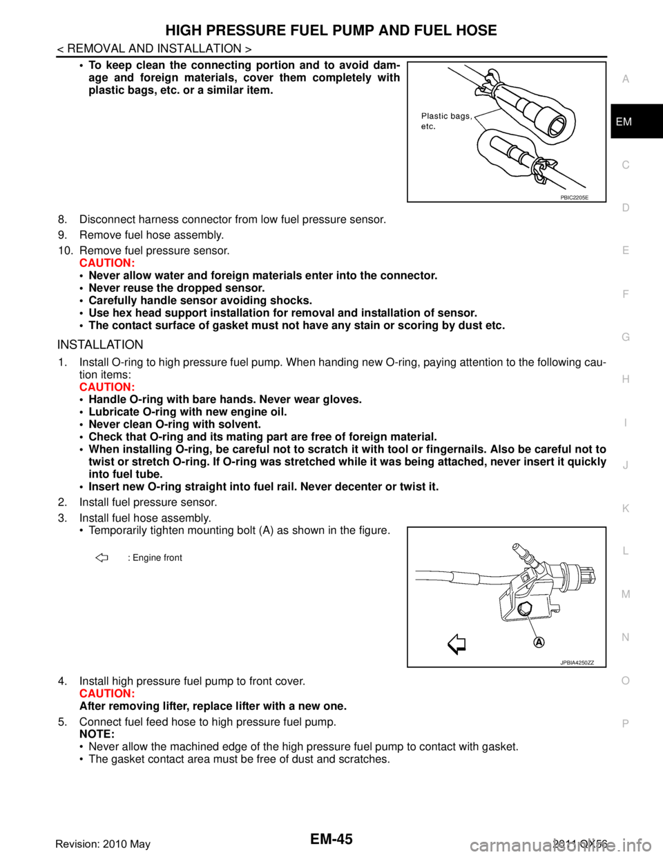
To keep clean the connecting portion and to avoid dam-
age and foreign materials, cover them completely with
plastic bags, etc. or a similar item.
8. Disconnect harness connector from low fuel pressure sensor.
9. Remove fuel hose assembly.
10. Remove fuel pressure sensor. CAUTION:
Never allow water and foreign mate rials enter into the connector.
Never reuse the dropped sensor.
Carefully handle sensor avoiding shocks.
Use hex head support installation fo r removal and installation of sensor.
The contact surface of gasket must not have any stain or scoring by dust etc.
INSTALLATION
1. Install O-ring to high pressure fuel pump. When handi ng new O-ring, paying attention to the following cau-
tion items:
CAUTION:
Handle O-ring with bare hands. Never wear gloves.
Lubricate O-ring with new engine oil.
Never clean O-ring with solvent.
Check that O-ring and its mating pa rt are free of foreign material.
When installing O-ring, be careful not to scratch it with tool or fingernails. Also be careful not to
twist or stretch O-ring. If O-ring was stretched wh ile it was being attached, never insert it quickly
into fuel tube.
Insert new O-ring straight into fu el rail. Never decenter or twist it.
2. Install fuel pressure sensor.
3. Install fuel hose assembly. Temporarily tighten mounting bolt (A) as shown in the figure.
4. Install high pressure fuel pump to front cover. CAUTION:
After removing lifter, replace lifter with a new one.
5. Connect fuel feed hose to high pressure fuel pump. NOTE:
Never allow the machined edge of the high pr essure fuel pump to contact with gasket.
The gasket contact area must be free of dust and scratches.
PBIC2205E
: Engine front
JPBIA4250ZZ
Revision: 2010 May2011 QX56
Page 2624 of 5598
EM-62
< REMOVAL AND INSTALLATION >
TIMING CHAIN
Removal and Installation
INFOID:0000000006289566
REMOVAL
1. Release fuel pressure. Refer to EC-153, "Work Procedure".
2. Drain engine coolant from radiator. Refer to CO-8, "
Draining".
3. Remove fan shroud (lower). Refer to CO-13, "
Exploded View".
4. Remove fan bracket. Refer to CO-16, "
Exploded View".
5. Remove drive belt auto-tensioner. Refer to EM-26, "
Exploded View".
6. Remove oil level gauge and oil level gauge guide. Refer to EM-57, "
Exploded View".
7. Move power steering oil pump to the posit ion without the hindrance for work. Refer to ST-48, "
Exploded
View".
8. Remove alternator, alternator bracket and alternator stay. Refer to CHG-25, "
Exploded View".
9. Move power steering reservoir tank to the position without the hindrance for work, and then remove Res- ervoir tank bracket. Refer to ST-54, "
Exploded View".
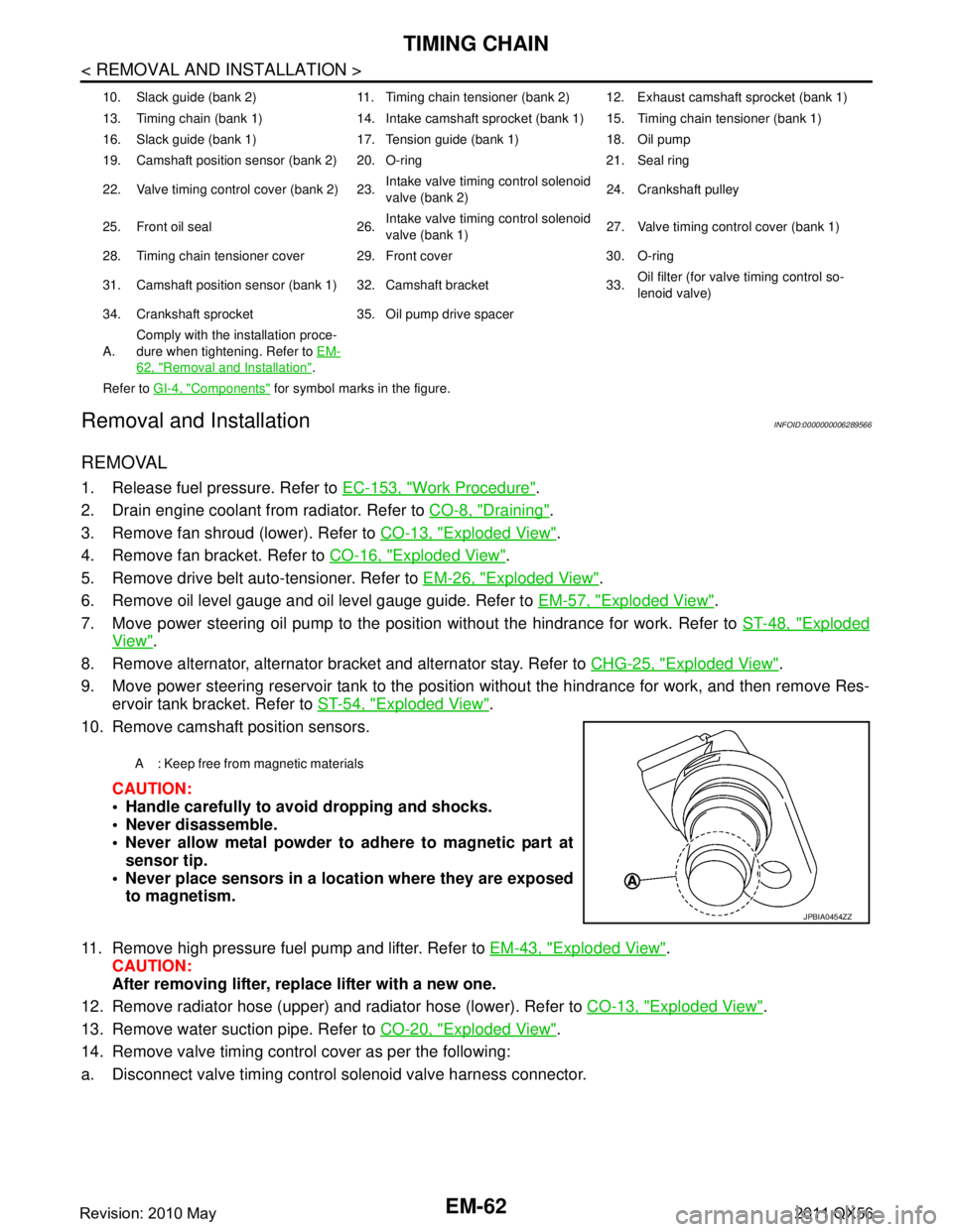
10. Remove camshaft position sensors.
CAUTION:
Handle carefully to avoid dropping and shocks.
Never disassemble.
Never allow metal powder to adhere to magnetic part atsensor tip.
Never place sensors in a lo cation where they are exposed
to magnetism.
11. Remove high pressure fuel pump and lifter. Refer to EM-43, "
Exploded View".
CAUTION:
After removing lifter, replace lifter with a new one.
12. Remove radiator hose (upper) and radiator hose (lower). Refer to CO-13, "
Exploded View".
13. Remove water suction pipe. Refer to CO-20, "
Exploded View".
14. Remove valve timing control cover as per the following:
a. Disconnect valve timing control solenoid valve harness connector.
10. Slack guide (bank 2) 11. Timing chain tensioner (bank 2) 12. Exhaust camshaft sprocket (bank 1)
13. Timing chain (bank 1) 14. Intake camshaft sprocket (bank 1) 15. Timing chain tensioner (bank 1)
16. Slack guide (bank 1) 17. Tension guide (bank 1) 18. Oil pump
19. Camshaft position sensor (bank 2) 20. O-ring 21. Seal ring
22. Valve timing control cover (bank 2) 23. Intake valve timing control solenoid
valve (bank 2)24. Crankshaft pulley
25. Front oil seal 26. Intake valve timing control solenoid
valve (bank 1)27. Valve timing control cover (bank 1)
28. Timing chain tensioner cover 29. Front cover 30. O-ring
31. Camshaft position sensor (bank 1) 32. Camshaft bracket 33. Oil filter (for valve timing control so-
lenoid valve)
34. Crankshaft sprocket 35. Oil pump drive spacer
A. Comply with the installation proce-
dure when tightening. Refer to
EM-
62, "Removal and Installation".
Refer to GI-4, "
Components" for symbol marks in the figure.
A : Keep free from magnetic materials
JPBIA0454ZZ
Revision: 2010 May2011 QX56
Page 2625 of 5598
TIMING CHAINEM-63
< REMOVAL AND INSTALLATION >
C
DE
F
G H
I
J
K L
M A
EM
NP
O
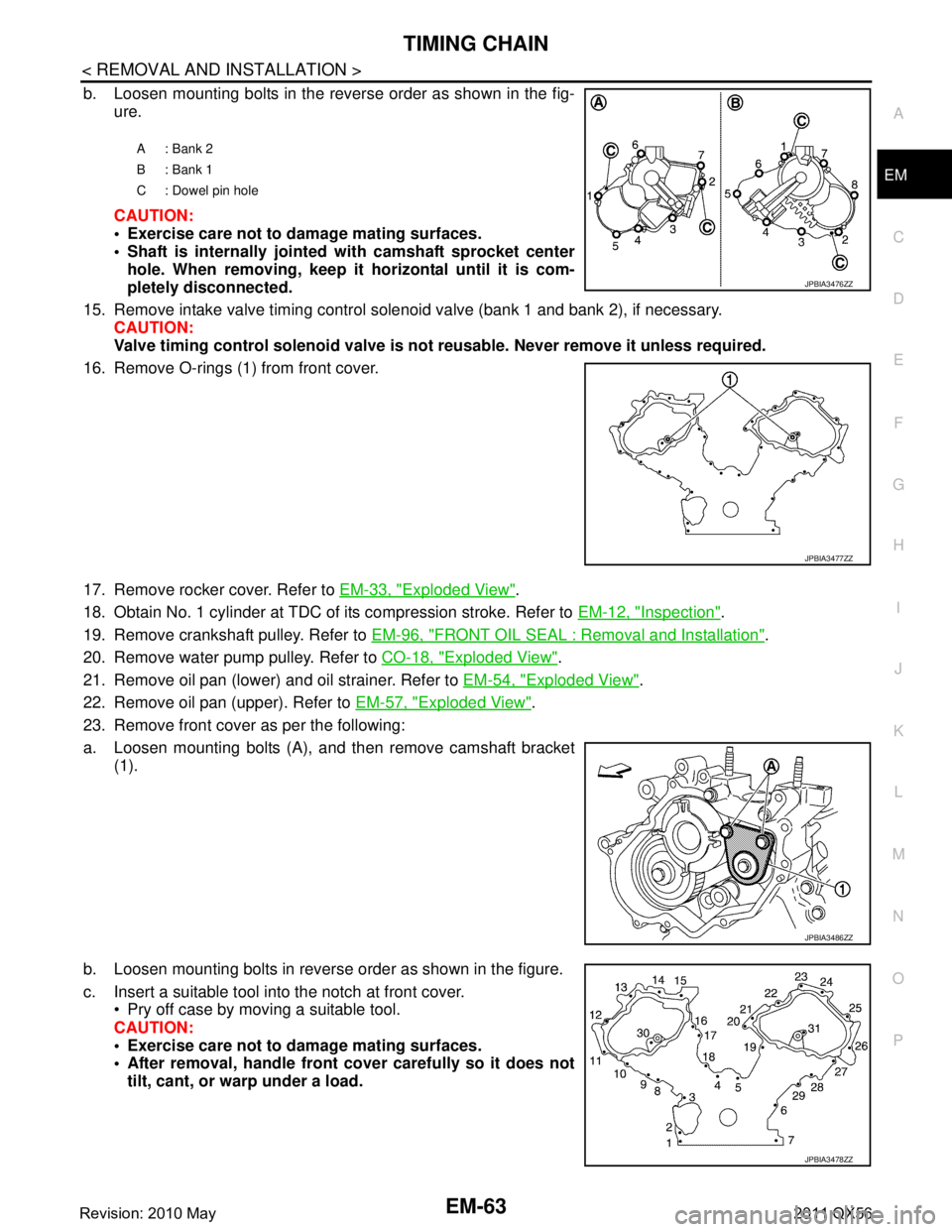
b. Loosen mounting bolts in the reverse order as shown in the fig-
ure.
CAUTION:
Exercise care not to damage mating surfaces.
Shaft is internally jointed with camshaft sprocket center
hole. When removing, keep it horizontal until it is com-
pletely disconnected.
15. Remove intake valve timing control solenoid valve (bank 1 and bank 2), if necessary. CAUTION:
Valve timing control solenoid valve is no t reusable. Never remove it unless required.
16. Remove O-rings (1) from front cover.
17. Remove rocker cover. Refer to EM-33, "
Exploded View".
18. Obtain No. 1 cylinder at TDC of its compression stroke. Refer to EM-12, "
Inspection".
19. Remove crankshaft pulley. Refer to EM-96, "
FRONT OIL SEAL : Removal and Installation".
20. Remove water pump pulley. Refer to CO-18, "
Exploded View".
21. Remove oil pan (lower) and oil strainer. Refer to EM-54, "
Exploded View".
22. Remove oil pan (upper). Refer to EM-57, "
Exploded View".
23. Remove front cover as per the following:
a. Loosen mounting bolts (A), and then remove camshaft bracket (1).
b. Loosen mounting bolts in reverse order as shown in the figure.
c. Insert a suitable tool into the notch at front cover. Pry off case by moving a suitable tool.
CAUTION:
Exercise care not to damage mating surfaces.
After removal, handle front cover carefully so it does not
tilt, cant, or warp under a load.
A: Bank 2
B: Bank 1
C : Dowel pin hole
JPBIA3476ZZ
JPBIA3477ZZ
JPBIA3486ZZ
JPBIA3478ZZ
Revision: 2010 May2011 QX56
Page 2634 of 5598
EM-72
< REMOVAL AND INSTALLATION >
TIMING CHAIN
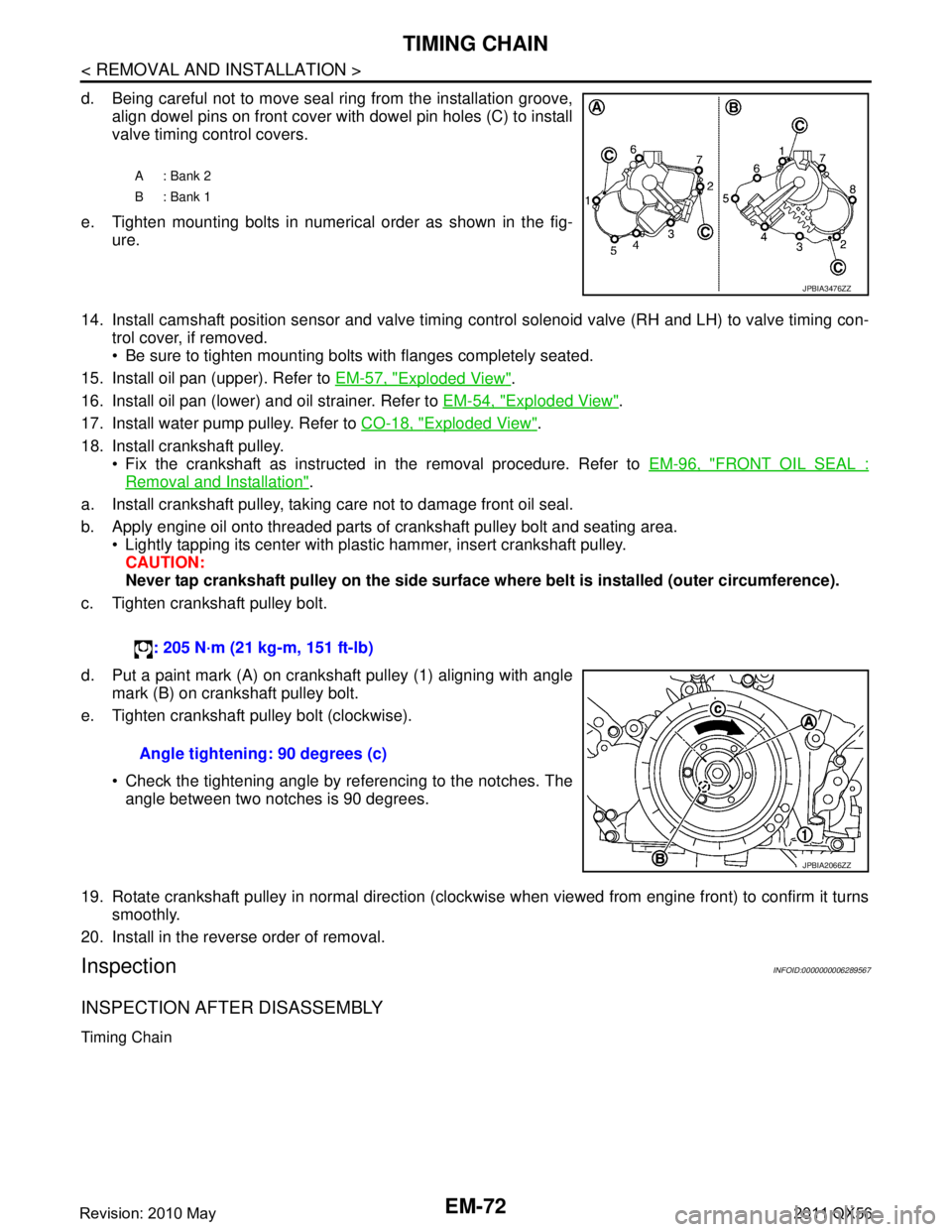
d. Being careful not to move seal ring from the installation groove,align dowel pins on front cover with dowel pin holes (C) to install
valve timing control covers.
e. Tighten mounting bolts in numerical order as shown in the fig- ure.
14. Install camshaft position sensor and valve timing c ontrol solenoid valve (RH and LH) to valve timing con-
trol cover, if removed.
Be sure to tighten mounting bolts with flanges completely seated.
15. Install oil pan (upper). Refer to EM-57, "
Exploded View".
16. Install oil pan (lower) and oil strainer. Refer to EM-54, "
Exploded View".
17. Install water pump pulley. Refer to CO-18, "
Exploded View".
18. Install crankshaft pulley. Fix the crankshaft as instructed in the removal procedure. Refer to EM-96, "
FRONT OIL SEAL :
Removal and Installation".
a. Install crankshaft pulley, taking care not to damage front oil seal.
b. Apply engine oil onto threaded parts of crankshaft pulley bolt and seating area. Lightly tapping its center with plastic hammer, insert crankshaft pulley.
CAUTION:
Never tap crankshaft pulley on the side surface wh ere belt is installed (outer circumference).
c. Tighten crankshaft pulley bolt.
d. Put a paint mark (A) on crankshaft pulley (1) aligning with angle mark (B) on crankshaft pulley bolt.
e. Tighten crankshaft pulley bolt (clockwise).
Check the tightening angle by referencing to the notches. Theangle between two notches is 90 degrees.
19. Rotate crankshaft pulley in normal direction (clockwise when viewed from engine front) to confirm it turns smoothly.
20. Install in the reverse order of removal.
InspectionINFOID:0000000006289567
INSPECTION AFTER DISASSEMBLY
Timing Chain
A: Bank 2
B: Bank 1
JPBIA3476ZZ
: 205 N·m (21 kg-m, 151 ft-lb)
Angle tightening: 90 degrees (c)
JPBIA2066ZZ
Revision: 2010 May2011 QX56
Page 2992 of 5598
GI-28
< PRECAUTION >
PRECAUTIONS
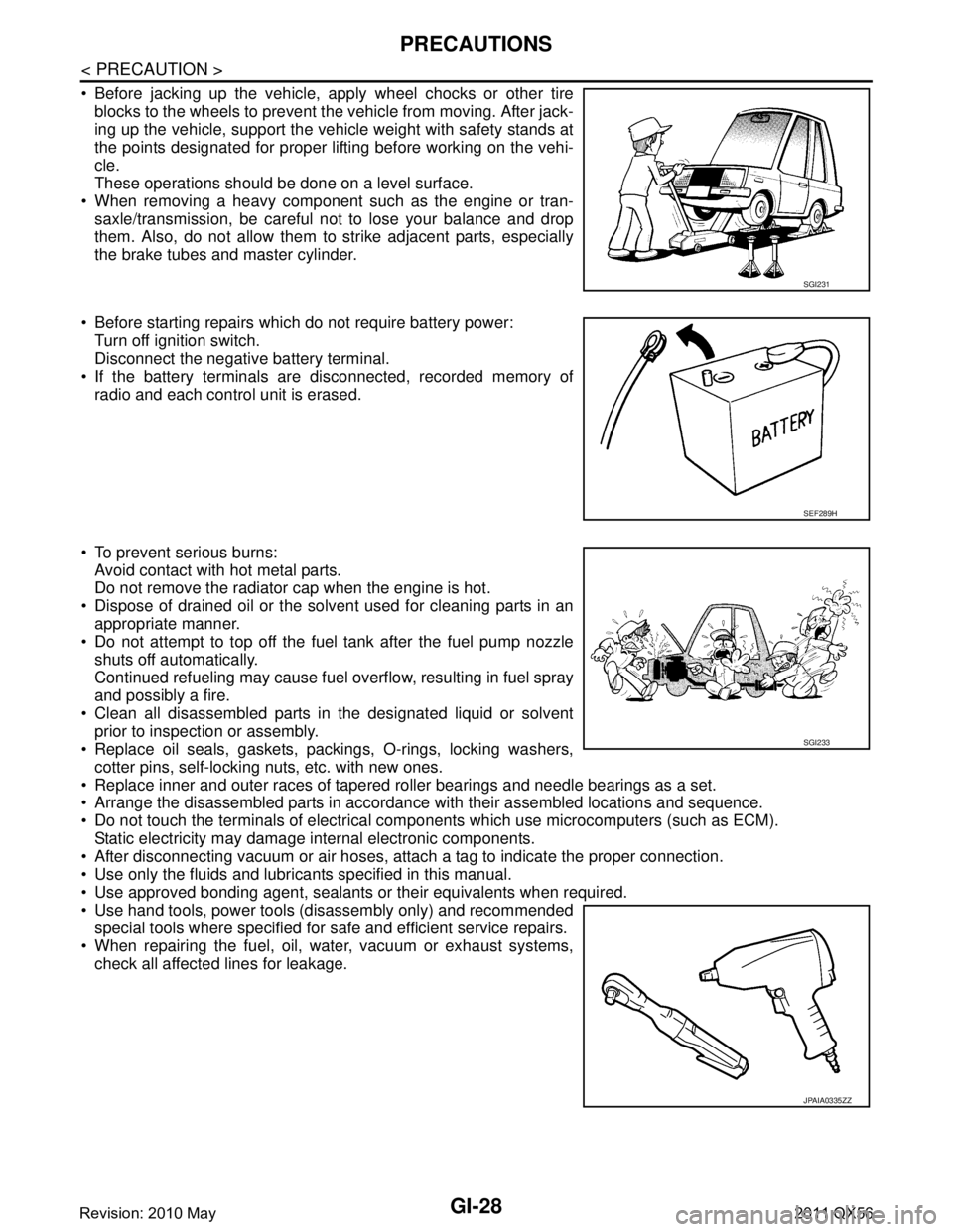
Before jacking up the vehicle, apply wheel chocks or other tireblocks to the wheels to prevent t he vehicle from moving. After jack-
ing up the vehicle, support the vehicle weight with safety stands at
the points designated for proper lifting before working on the vehi-
cle.
These operations should be done on a level surface.
When removing a heavy component such as the engine or tran- saxle/transmission, be careful not to lose your balance and drop
them. Also, do not allow them to strike adjacent parts, especially
the brake tubes and master cylinder.
Before starting repairs which do not require battery power: Turn off ignition switch.
Disconnect the negative battery terminal.
If the battery terminals are disconnected, recorded memory of
radio and each control unit is erased.
To prevent serious burns: Avoid contact with hot metal parts.
Do not remove the radiator cap when the engine is hot.
Dispose of drained oil or the solvent used for cleaning parts in an appropriate manner.
Do not attempt to top off the fuel tank after the fuel pump nozzle
shuts off automatically.
Continued refueling may cause fuel overflow, resulting in fuel spray
and possibly a fire.
Clean all disassembled parts in the designated liquid or solvent prior to inspection or assembly.
Replace oil seals, gaskets, packings, O-rings, locking washers,
cotter pins, self-locking nuts, etc. with new ones.
Replace inner and outer races of tapered roller bearings and needle bearings as a set.
Arrange the disassembled parts in accordance with their assembled locations and sequence.
Do not touch the terminals of electrical com ponents which use microcomputers (such as ECM).
Static electricity may damage internal electronic components.
After disconnecting vacuum or air hoses, atta ch a tag to indicate the proper connection.
Use only the fluids and lubricants specified in this manual.
Use approved bonding agent, sealants or their equivalents when required.
Use hand tools, power tools (disassembly only) and recommended special tools where specified for safe and efficient service repairs.
When repairing the fuel, oil, water, vacuum or exhaust systems, check all affected lines for leakage.
SGI231
SEF289H
SGI233
JPAIA0335ZZ
Revision: 2010 May2011 QX56
Page 3046 of 5598
BACK DOOR WINDOW GLASSGW-17
< REMOVAL AND INSTALLATION >
C
DE
F
G H
I
J
L
M A
B
GW
N
O P
3. Remove rear wiper arm. Refer to WW-74, "Removal and Installation".
4. Remove rear wiper motor. Refer to WW-76, "
Removal and Installation".
5. Remove back door window glass molding using a pliers. Refer to GW-16, "
Exploded View".
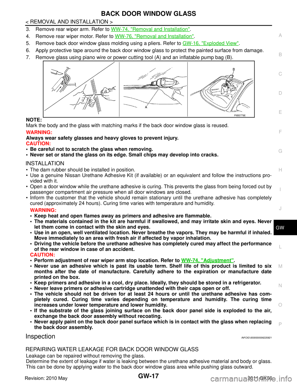
6. Apply protective tape around the back door window gl ass to protect the painted surface from damage.
7. Remove glass using piano wire or power cutting tool (A) and an inflatable pump bag (B).
NOTE:
Mark the body and the glass with matching ma rks if the back door window glass is reused.
WARNING:
Always wear safety glasses and heavy gloves to prevent injury.
CAUTION:
Be careful not to scratch the glass when removing.
Never set or stand the glass on its edge . Small chips may develop into cracks.
INSTALLATION
The dam rubber should be installed in position.
Use a genuine Nissan Urethane Adhesive Kit (if available) or an equivalent and follow the instructions pro-
vided with it.
Open a door window while the urethane adhesive is curing. This prevents the glass from being forced out by
passenger compartment air pressure when all door windows are closed.
Inform the customer that the v ehicle should remain stationary until the urethane adhesive has completely
cured (approximately 24 hours). Curing time varies with temperature and humidity.
WARNING:
Keep heat and open flames away as primers and adhesive are flammable.
The materials contained in the kit are harmful if swallowed, and may irritate skin and eyes. Never
let them come in contact with the skin and eyes.
Use in an open, well ventilated location. Never br eathe the vapors. They may be harmful if inhaled.
Move immediately to an area with fresh air if affected by vapor inhalation.
Driving the vehicle before the urethane adhesive has completely cured may affect the performance
of the rear window in case of an accident.
CAUTION:
Perform adjustment of rear wipe r arm stop location. Refer to WW-74, "
Adjustment".
Never use an adhesive which is past its usable term. Shelf life of this product is limited to six
months after the date of manufacture. Carefull y adhere to the expiration or manufacture date
printed on the box.
Keep primers and adhesive in a cool, dry place. Id eally, they should be stored in a refrigerator.
Never leave primers or adhesive cartridge unattended with their caps open or off.
The vehicle should not be driven for at least 24 hours or until the urethane adhesive has com-
pletely cured. Curing time varies depending on temperature and humidity. The curing time
increases under lower temperature and lower humidity.
If the substrate of the glass joining surface on th e back door panel side is exploded to the air,
exchange the back door assembly without recoating.
Never apply paint on the back door panel surface wh ich is in contact with the glass when replacing
the back door assembly.
InspectionINFOID:0000000006220821
REPAIRING WATER LEAKAGE FOR BACK DOOR WINDOW GLASS
Leakage can be repaired without removing the glass.
Determine the extent of leakage if water is leaki ng between the urethane adhesive material and body or glass.
This can be done by applying water to the back door window glass area while pushing glass outward.
PIIB5779E
Revision: 2010 May2011 QX56
Page 3666 of 5598
OIL PUMPLU-13
< REMOVAL AND INSTALLATION >
C
DE
F
G H
I
J
K L
M A
LU
NP
O
OIL PUMP
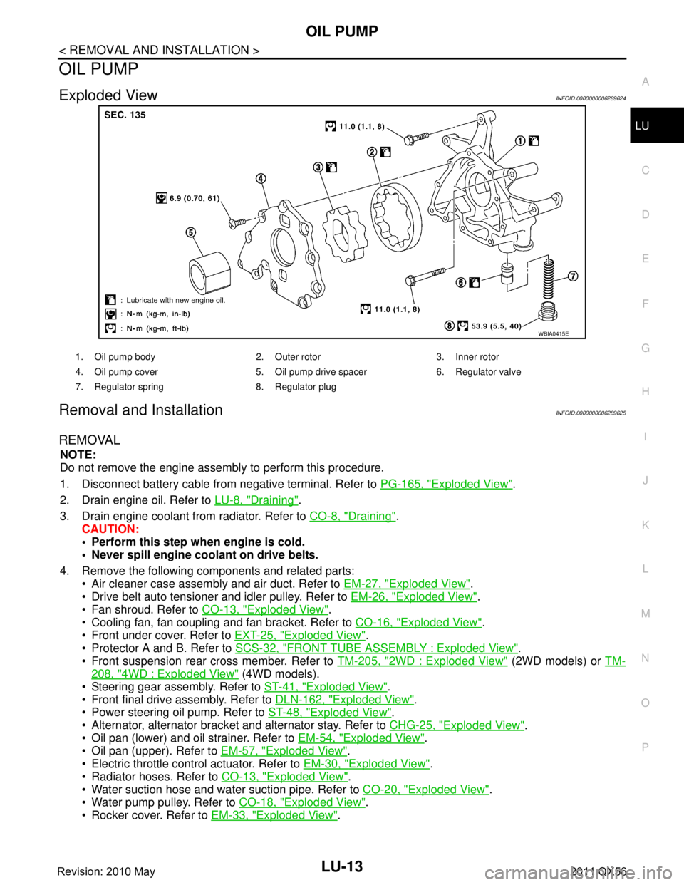
Exploded ViewINFOID:0000000006289624
Removal and InstallationINFOID:0000000006289625
REMOVAL
NOTE:
Do not remove the engine assembly to perform this procedure.
1. Disconnect battery cable from
negative terminal. Refer to PG-165, "
Exploded View".
2. Drain engine oil. Refer to LU-8, "
Draining".
3. Drain engine coolant from radiator. Refer to CO-8, "
Draining".
CAUTION:
Perform this step when engine is cold.
Never spill engine coolant on drive belts.
4. Remove the following components and related parts: Air cleaner case assembly and air duct. Refer to EM-27, "
Exploded View".
Drive belt auto tensioner and idler pulley. Refer to EM-26, "
Exploded View".
Fan shroud. Refer to CO-13, "
Exploded View".
Cooling fan, fan coupling and fan bracket. Refer to CO-16, "
Exploded View".
Front under cover. Refer to EXT-25, "
Exploded View".
Protector A and B. Refer to SCS-32, "
FRONT TUBE ASSEMBLY : Exploded View".
Front suspension rear cross member. Refer to TM-205, "
2WD : Exploded View" (2WD models) or TM-
208, "4WD : Exploded View" (4WD models).
Steering gear assembly. Refer to ST-41, "
Exploded View".
Front final drive assembly. Refer to DLN-162, "
Exploded View".
Power steering oil pump. Refer to ST-48, "
Exploded View".
Alternator, alternator bracket and alternator stay. Refer to CHG-25, "
Exploded View".
Oil pan (lower) and oil strainer. Refer to EM-54, "
Exploded View".
Oil pan (upper). Refer to EM-57, "
Exploded View".
Electric throttle control actuator. Refer to EM-30, "
Exploded View".
Radiator hoses. Refer to CO-13, "
Exploded View".
Water suction hose and water suction pipe. Refer to CO-20, "
Exploded View".
Water pump pulley. Refer to CO-18, "
Exploded View".
Rocker cover. Refer to EM-33, "
Exploded View".
WBIA0415E
1. Oil pump body 2. Outer rotor 3. Inner rotor
4. Oil pump cover 5. Oil pump drive spacer 6. Regulator valve
7. Regulator spring 8. Regulator plug
Revision: 2010 May2011 QX56
Page 3682 of 5598
MA-12
< PERIODIC MAINTENANCE >
ENGINE MAINTENANCE
ENGINE MAINTENANCE
DRIVE BELTS
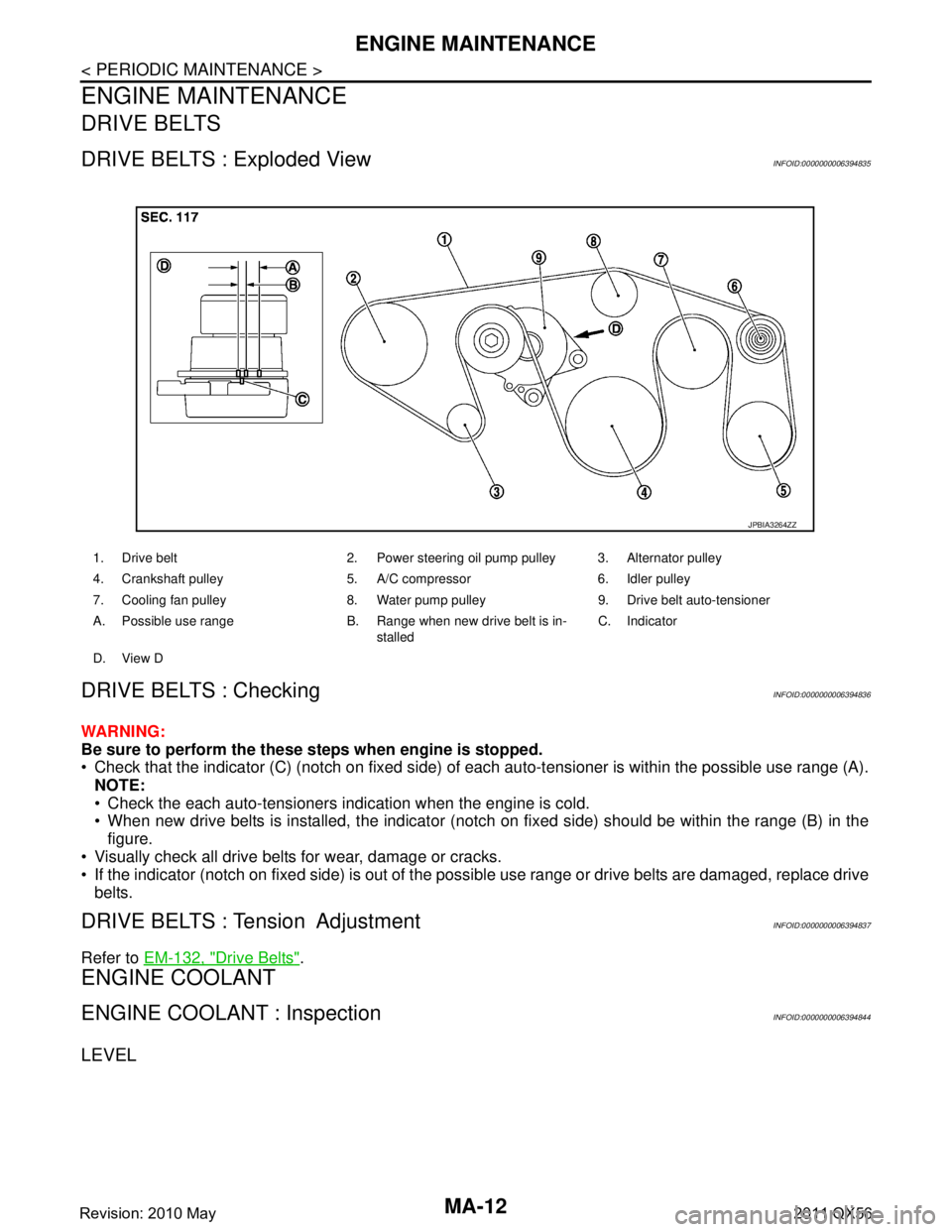
DRIVE BELTS : Exploded ViewINFOID:0000000006394835
DRIVE BELTS : CheckingINFOID:0000000006394836
WARNING:
Be sure to perform the these steps when engine is stopped.
Check that the indicator (C) (notch on fixed side) of each auto-tensioner is within the possible use range (A).
NOTE:
Check the each auto-tensioners indication when the engine is cold.
When new drive belts is installed, the indicator (notch on fixed side) should be within the range (B) in the\
figure.
Visually check all drive belts for wear, damage or cracks.
If the indicator (notch on fixed side) is out of the possible use range or drive belts are damaged, replace drive
belts.
DRIVE BELTS : Tension AdjustmentINFOID:0000000006394837
Refer to EM-132, "Drive Belts".
ENGINE COOLANT
ENGINE COOLANT : InspectionINFOID:0000000006394844
LEVEL
1. Drive belt 2. Power steering oil pump pulley 3. Alternator pulley
4. Crankshaft pulley 5. A/C compressor 6. Idler pulley
7. Cooling fan pulley 8. Water pump pulley 9. Drive belt auto-tensioner
A. Possible use range B. Range when new drive belt is in-
stalledC. Indicator
D. View D
JPBIA3264ZZ
Revision: 2010 May2011 QX56