2011 INFINITI QX56 water pump
[x] Cancel search: water pumpPage 2369 of 5598
![INFINITI QX56 2011 Factory Service Manual
P0453 EVAP CONTROL SYSTEM PRESSURE SENSOREC-345
< DTC/CIRCUIT DIAGNOSIS > [VK56VD]
C
D
E
F
G H
I
J
K L
M A
EC
NP
O
2. Check if water will drain from the EVAP canister (1).
- EVAP canister vent contro INFINITI QX56 2011 Factory Service Manual
P0453 EVAP CONTROL SYSTEM PRESSURE SENSOREC-345
< DTC/CIRCUIT DIAGNOSIS > [VK56VD]
C
D
E
F
G H
I
J
K L
M A
EC
NP
O
2. Check if water will drain from the EVAP canister (1).
- EVAP canister vent contro](/manual-img/42/57033/w960_57033-2368.png)
P0453 EVAP CONTROL SYSTEM PRESSURE SENSOREC-345
< DTC/CIRCUIT DIAGNOSIS > [VK56VD]
C
D
E
F
G H
I
J
K L
M A
EC
NP
O
2. Check if water will drain from the EVAP canister (1).
- EVAP canister vent control valve (2)
Does water drain from EVAP canister?
YES >> GO TO 17.
NO >> GO TO 19.
17.CHECK EVAP CANISTER
Weigh the EVAP canister with the EV AP canister vent control valve and EVAP control system pressure sensor
attached.
The weight should be less than 2.5 kg (5.5 lb).
Is the inspection result normal?
YES >> GO TO 19.
NO >> GO TO 18.
18.DETECT MALFUNCTIONING PART
Check the following.
EVAP canister for damage
EVAP hose between EVAP canister and vehi cle frame for clogging or poor connection
>> Repair hose or replace EVAP canister. Refer to FL-10, "
Hydraulic Layout".
19.CHECK INTERMITTENT INCIDENT
Refer to GI-40, "
Intermittent Incident".
>> INSPECTION END
Component Inspection (EVAP Cont rol System Pressure Sensor)INFOID:0000000006288365
1.CHECK EVAP CONTROL SYSTEM PRESSURE SENSOR
1. Turn ignition switch OFF.
2. Remove EVAP control system pressure sensor with its harness connector. Always replace O-ring with a new one.
3. Install a vacuum pump to EVAP control system pressure sensor.
4. Turn ignition switch ON and check output voltage between ECM harness connector terminals under the following conditions.
CAUTION:
Always calibrate the vacuum pu mp gauge when using it.
Never apply below -93.3 kPa (-0.952 kg/cm
2, -13.53 psi) or pressure over 101.3 kPa (1.033 kg/cm2,
14.69 psi).
Is the inspection result normal?
YES >> INSPECTION END
NO >> Replace EVAP control system pressure sensor.
JSBIA0692ZZ
ECM Condition
[Applied vacuum kPa (kg/cm
2, psi)] Voltage (V)
Connector +–
Terminal Terminal
E80 143 150 Not applied 1.8 - 4.8
-26.7 (-0.272, -3.87) 2.1 to 2.5 lower than above value
Revision: 2010 May2011 QX56
Page 2424 of 5598
![INFINITI QX56 2011 Factory Service Manual
EC-400
< DTC/CIRCUIT DIAGNOSIS >[VK56VD]
P1217 ENGINE OVER TEMPERATURE
P1217 ENGINE OVER TEMPERATURE
DTC LogicINFOID:0000000006217909
DTC DETECTION LOGIC
NOTE:
If DTC P1217 is displayed with DTC UX INFINITI QX56 2011 Factory Service Manual
EC-400
< DTC/CIRCUIT DIAGNOSIS >[VK56VD]
P1217 ENGINE OVER TEMPERATURE
P1217 ENGINE OVER TEMPERATURE
DTC LogicINFOID:0000000006217909
DTC DETECTION LOGIC
NOTE:
If DTC P1217 is displayed with DTC UX](/manual-img/42/57033/w960_57033-2423.png)
EC-400
< DTC/CIRCUIT DIAGNOSIS >[VK56VD]
P1217 ENGINE OVER TEMPERATURE
P1217 ENGINE OVER TEMPERATURE
DTC LogicINFOID:0000000006217909
DTC DETECTION LOGIC
NOTE:
If DTC P1217 is displayed with DTC UXXXX, perform the trouble diagnosis for DTC UXXXX.
If DTC P1217 is displayed with DTC P0607, perfo rm the trouble diagnosis for DTC P0607. Refer to
EC-378, "
DTC Logic".
If DTC P1217 is displayed with DTC P0527, perfo rm the trouble diagnosis for DTC P0527. Refer to
EC-367, "
DTC Logic".
If the cooling fan or any of other components in the cooling system has a malfunction, engine coolant temper-
ature increases.
When the engine coolant temperature reaches an abnorma lly high temperature condition, a malfunction is
indicated.
CAUTION:
When a malfunction is indicated, al ways replace the coolant. Refer to CO-8, "
Draining" and CO-9,
"Refilling". Also, replace the engine oil. Refer to LU-8, "Draining" and LU-8, "Refilling".
1. Fill radiator with coolant up to specified level with a filling speed of 2 liters per minute. Always use
coolant with the proper mixture ratio. Refer to MA-11, "
Anti-Freeze Coolant Mixture Ratio".
2. After refilling coolant, run engine to en sure that no water-flow noise is emitted.
DTC CONFIRMATION PROCEDURE
1.PERFORM COMPONENT FUNCTION CHECK
Perform component function check. Refer to EC-400, "
Component Function Check".
NOTE:
Use component function check to check the overall functi on of the cooling fan. During this check, a DTC might
not be confirmed.
Is the inspection result normal?
YES >> INSPECTION END
NO >> Go to EC-401, "
Diagnosis Procedure".
Component Function CheckINFOID:0000000006217910
1.PERFORM COMPONENT FUNCTION CHECK-I
WARNING:
Never remove the reservoir tank cap when the engi ne is hot. Serious burns could be caused by high
pressure fluid escaping from the radiator.
Wrap a thick cloth around cap. Carefully remove the cap by turning it a quarter turn to allow built-up
pressure to escape. Then turn the cap all the way off.
DTC No. Trouble diagnosis name DTC detecting condition Possible cause
P1217 Engine over temperature
(Overheat) Cooling fan does not operate properly
(Overheat).
Cooling fan system does not operate properly (Overheat).
Engine coolant is not within the specified quantity. Harness or connectors
(The cooling fan circuit is open or shorted.)
IPDM E/R
Electrically-controlled cooling fan coupling
Cooling fan speed sensor
Radiator hose
Radiator
Reservoir tank cap
Water pump
Thermostat
Revision: 2010 May2011 QX56
Page 2426 of 5598
![INFINITI QX56 2011 Factory Service Manual
EC-402
< DTC/CIRCUIT DIAGNOSIS >[VK56VD]
P1217 ENGINE OVER TEMPERATURE
YES >> GO TO 3.
NO >> GO TO 4.
3.CHECK ENGINE COOLANT LEAKAGE-II
Check the following for leakage.
Hose
Radiator
Water pump
INFINITI QX56 2011 Factory Service Manual
EC-402
< DTC/CIRCUIT DIAGNOSIS >[VK56VD]
P1217 ENGINE OVER TEMPERATURE
YES >> GO TO 3.
NO >> GO TO 4.
3.CHECK ENGINE COOLANT LEAKAGE-II
Check the following for leakage.
Hose
Radiator
Water pump](/manual-img/42/57033/w960_57033-2425.png)
EC-402
< DTC/CIRCUIT DIAGNOSIS >[VK56VD]
P1217 ENGINE OVER TEMPERATURE
YES >> GO TO 3.
NO >> GO TO 4.
3.CHECK ENGINE COOLANT LEAKAGE-II
Check the following for leakage.
Hose
Radiator
Water pump
>> Repair or replace malfunctioning part.
4.CHECK RESERVOIR TANK CAP
Check reservoir tank cap. Refer to CO-11, "
RESERVOIR TANK CAP : Inspection".
Is the inspection result normal?
YES >> GO TO 5.
NO >> Replace reservoir tank cap.
5.CHECK THERMOSTAT
Check thermostat. Refer to CO-21, "
Inspection".
Is the inspection result normal?
YES >> GO TO 6.
NO >> Replace thermostat. Refer to CO-20, "
Removal and Installation".
6.CHECK ENGINE COOLANT TEMPERATURE SENSOR
Refer to EC-216, "
Component Inspection (Engine Coolant Temperature Sensor)".
Is the inspection result normal?
YES >> GO TO 7.
NO >> Replace engine coolant temperature sensor. Refer to EM-86, "
Exploded View".
7.CHECK MAIN 12 CAUSES
If the cause cannot be isolated, check the CO-6, "
TroubleshootingChart".
>> INSPECTION END
Revision: 2010 May2011 QX56
Page 2548 of 5598
![INFINITI QX56 2011 Factory Service Manual
EC-524
< SYMPTOM DIAGNOSIS >[VK56VD]
ENGINE CONTROL SYSTEM SYMPTOMS
SYMPTOM DIAGNOSIS
ENGINE CONTROL SYSTEM SYMPTOMS
Symptom TableINFOID:0000000006218028
SYSTEM — BASIC ENGINE CONTROL SYSTEM
SYMPTO INFINITI QX56 2011 Factory Service Manual
EC-524
< SYMPTOM DIAGNOSIS >[VK56VD]
ENGINE CONTROL SYSTEM SYMPTOMS
SYMPTOM DIAGNOSIS
ENGINE CONTROL SYSTEM SYMPTOMS
Symptom TableINFOID:0000000006218028
SYSTEM — BASIC ENGINE CONTROL SYSTEM
SYMPTO](/manual-img/42/57033/w960_57033-2547.png)
EC-524
< SYMPTOM DIAGNOSIS >[VK56VD]
ENGINE CONTROL SYSTEM SYMPTOMS
SYMPTOM DIAGNOSIS
ENGINE CONTROL SYSTEM SYMPTOMS
Symptom TableINFOID:0000000006218028
SYSTEM — BASIC ENGINE CONTROL SYSTEM
SYMPTOM
Reference
page
HARD/NO START/RESTART (EXCP. HA)
ENGINE STALL
HESITATION/SURGING/FLAT SPOT
SPARK KNOCK/DETONATION
LACK OF POWER/POOR ACCELERATION
HIGH IDLE/LOW IDLE
ROUGH IDLE/HUNTING
IDLING VIBRATION
SLOW/NO RETURN TO IDLE
OVERHEATS/WATER TEMPERATURE HIGH
EXCESSIVE FUEL CONSUMPTION
EXCESSIVE OIL CONSUMPTION
BATTERY DEAD (UNDER CHARGE)
Warranty symptom code AA AB AC AD AE AF AG AH AJ AK AL AM HA
Fuel Low pressure fuel pump circuit 11232 22 3 2 EC-512
Low fuel pressure sensor circuit 4 4EC-483
Fuel pressure regulator system 334444444 4EC-198
Fuel injector circuit 11232 22 2EC-498
Evaporative emission system 334444444 4EC-532
FRP sensor circuit 11222 22 2EC-276EC-279
High pressure fuel pump circuit 4 3
EC-501
Air Positive crankcase ventilation sys-
tem 334444444 41
EC-534
Incorrect idle speed adjustment 1 1 1 1 1 EC-139
Electric throttle control actuator 112332222 2 2EC-460EC-466
IgnitionIncorrect ignition timing adjustment33111 11 1
EC-139
Ignition circuit 11222 22 2EC-506
Main power supply and ground circuit 22333 33 23 EC-168
Revision: 2010 May2011 QX56
Page 2552 of 5598
![INFINITI QX56 2011 Factory Service Manual
E C -528
< SYMPTOM DIAGNOSIS >[VK56VD]
ENGINE CONTROL SYSTEM SYMPTOMS
1 - 6: The numbers refer to the order of inspection.Lubrica-
tion
Oil pan/Oil strainer/Oil pump/Oil
filter/Oil gallery/Oil coole INFINITI QX56 2011 Factory Service Manual
E C -528
< SYMPTOM DIAGNOSIS >[VK56VD]
ENGINE CONTROL SYSTEM SYMPTOMS
1 - 6: The numbers refer to the order of inspection.Lubrica-
tion
Oil pan/Oil strainer/Oil pump/Oil
filter/Oil gallery/Oil coole](/manual-img/42/57033/w960_57033-2551.png)
E C -528
< SYMPTOM DIAGNOSIS >[VK56VD]
ENGINE CONTROL SYSTEM SYMPTOMS
1 - 6: The numbers refer to the order of inspection.Lubrica-
tion
Oil pan/Oil strainer/Oil pump/Oil
filter/Oil gallery/Oil cooler 55555 55 5 EM-56
EM-60
LU-9
LU-12
LU-14
Oil level (Low)/Filthy oil
LU-7
Cooling
Radiator/Hose/Radiator filler cap
55555 55 45 CO-11
CO-11
Thermostat 5
CO-21
Water pumpCO-19
Water galleryEM-115
Cooling fan
5CO-17
Coolant level (Low)/Contaminat-
ed coolant
CO-8
IVIS (INFINITI Vehicle Immobilizer System —
NATS)11
SEC-48
SYMPTOM
Reference
page
HARD/NO START/RESTART (EXCP. HA)
ENGINE STALL
HESITATION/SURGING/FLAT SPOT
SPARK KNOCK/DETONATION
LACK OF POWER/POOR ACCELERATION
HIGH IDLE/LOW IDLE
ROUGH IDLE/HUNTING
IDLING VIBRATION
SLOW/NO RETURN TO IDLE
OVERHEATS/WATER TEMPERATURE HIGH
EXCESSIVE FUEL CONSUMPTION
EXCESSIVE OIL CONSUMPTION
BATTERY DEAD (UNDER CHARGE)
Warranty symptom code AA AB AC AD AE AF AG AH AJ AK AL AM HA
Revision: 2010 May2011 QX56
Page 2578 of 5598

EM-16
< BASIC INSPECTION >
COMPRESSION PRESSURE
COMPRESSION PRESSURE
InspectionINFOID:0000000006289521
1. Warm up engine thoroughly. Then, stop it.
2. Release fuel pressure. Refer to EC-153, "
Work Procedure".
CAUTION:
If CONSULT-III is not used to release fuel pr essure leave the fuel pump fuse disconnected until
step 7.
3. Remove fuel pump fuse in IPDM E/R. NOTE:
For the fuse number, refer to EC-114, "
Wiring Diagram".
For the fuse arrangement, refer to PG-143, "
Fuse, Connector and Terminal Arrangement".
4. Remove engine cover. Refer to EM-25, "
Exploded View".
5. Remove ignition coil and spark plug from each cylinder. Refer to EM-29, "
Exploded View".
6. Connect engine tachometer (not required in use of CONSULT-III).
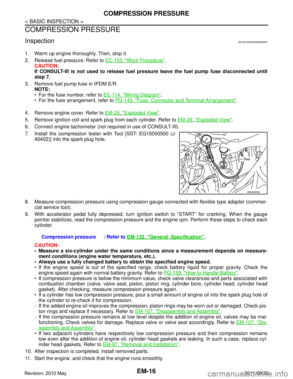
7. Install the compression tester with Tool [SST: EG15050500 (J- 45402)] into the spark plug hole.
8. Measure compression pressure using compressi on gauge connected with flexible type adapter (commer-
cial service tool).
9. With accelerator pedal fully depressed, turn ignition switch to “START” for cranking. When the gauge pointer stabilizes, read the compression pressure and the engine rpm. Perform these steps to check each
cylinder.
CAUTION:
Measure a six-cylinder under the same conditio ns since a measurement depends on measure-
ment conditions (engine water temperature, etc.).
Always use a fully changed battery to obtain the specified engine speed.
If the engine speed is out of the specified range, c heck battery liquid for proper gravity. Check the
engine speed again with normal battery gravity. Refer to PG-159, "
How to Handle Battery".
If compression pressure is below the minimum value, check valve clearances and parts associated with combustion chamber (valve, valve seat, piston, pi ston ring, cylinder bore, cylinder head, cylinder head
gasket). After checking, measure compression pressure again.
If a cylinder has low compression pressure, pour a small amount of engine oil into the spark plug hole of the cylinder to re-check it for compression.
- If the added engine oil improves the compression, pi ston rings may be worn out or damaged. Check pis-
ton rings and replace if necessary. Refer to EM-107, "
Disassembly and Assembly".
- If the compression pressure remains at low level despite the addition of engine oil, valves may be mal- functioning. Check valves for damage. Replace valve or valve seat accordingly. Refer to EM-107, "
Dis-
assembly and Assembly".
If two adjacent cylinders have respectively low co mpression pressure and their compression remains
low even after the addition of engine oil, cylinder head gaskets are leaking. In such a case, replace cyl-
inder head gaskets. Refer to EM-87, "
Removal and Installation".
10. After inspection is completed, install removed parts.
11. Start the engine, and check that the engine runs smoothly.
WBIA0605E
Compression pressure : Refer to EM-132, "GeneralSpecification".
Revision: 2010 May2011 QX56
Page 2581 of 5598

NOISE, VIBRATION AND HARSHNESS (NVH) TROUBLESHOOTINGEM-19
< SYMPTOM DIAGNOSIS >
C
DE
F
G H
I
J
K L
M A
EM
NP
O
Use the Chart Below to Help You Find the Cause of the SymptomINFOID:0000000006289523
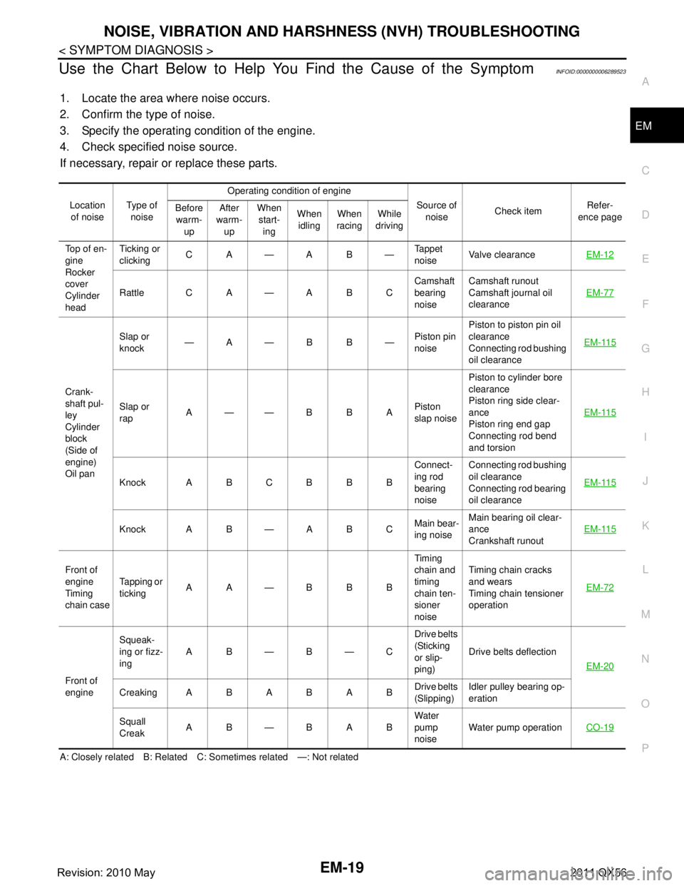
1. Locate the area where noise occurs.
2. Confirm the type of noise.
3. Specify the operating condition of the engine.
4. Check specified noise source.
If necessary, repair or replace these parts.
A: Closely related B: Related C: Sometimes related —: Not related Location
of noise Type of
noise Operating condition of engine
Source of noise Check item Refer-
ence page
Before
warm- up After
warm- up When
start- ing When
idling When
racing While
driving
Top of en-
gine
Rocker
cover
Cylinder
head Ticking or
clicking
CA—AB— Tappet
noiseValve clearance
EM-12
Rattle C A — A B C Camshaft
bearing
noiseCamshaft runout
Camshaft journal oil
clearance
EM-77
Crank-
shaft pul-
ley
Cylinder
block
(Side of
engine)
Oil panSlap or
knock
—A—B B—
Piston pin
noisePiston to piston pin oil
clearance
Connecting rod bushing
oil clearance
EM-115
Slap or
rap
A——B B A
Piston
slap noisePiston to cylinder bore
clearance
Piston ring side clear-
ance
Piston ring end gap
Connecting rod bend
and torsion
EM-115
Knock A B C B B B
Connect-
ing rod
bearing
noiseConnecting rod bushing
oil clearance
Connecting rod bearing
oil clearance
EM-115
Knock A B — A B C
Main bear-
ing noiseMain bearing oil clear-
ance
Crankshaft runout
EM-115
Front of
engine
Timing
chain caseTapping or
ticking
AA—BBB Timing
chain and
timing
chain ten-
sioner
noiseTiming chain cracks
and wears
Timing chain tensioner
operation
EM-72
Front of
engineSqueak-
ing or fizz-
ing
AB—B—C Drive belts
(Sticking
or slip-
ping)Drive belts deflection
EM-20
CreakingABABAB Drive belts
(Slipping)Idler pulley bearing op-
eration
Squall
Creak AB—BAB Water
pump
noiseWater pump operation
CO-19
Revision: 2010 May2011 QX56
Page 2582 of 5598

EM-20
< PERIODIC MAINTENANCE >
DRIVE BELTS
PERIODIC MAINTENANCE
DRIVE BELTS
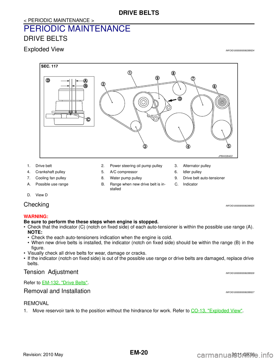
Exploded ViewINFOID:0000000006289524
CheckingINFOID:0000000006289525
WARNING:
Be sure to perform the these steps when engine is stopped.
Check that the indicator (C) (notch on fixed side) of each auto-tensioner is within the possible use range (A).
NOTE:
Check the each auto-tensioners indication when the engine is cold.
When new drive belts is installed, the indicator (notch on fixed side) should be within the range (B) in the\
figure.
Visually check all drive belts for wear, damage or cracks.
If the indicator (notch on fixed side) is out of the possible use range or drive belts are damaged, replace drive
belts.
Tension AdjustmentINFOID:0000000006289526
Refer to EM-132, "Drive Belts".
Removal and InstallationINFOID:0000000006289527
REMOVAL
1. Move reservoir tank to the position without the hindrance for work. Refer to CO-13, "Exploded View".
1. Drive belt 2. Power steering oil pump pulley 3. Alternator pulley
4. Crankshaft pulley 5. A/C compressor 6. Idler pulley
7. Cooling fan pulley 8. Water pump pulley 9. Drive belt auto-tensioner
A. Possible use range B. Range when new drive belt is in-
stalledC. Indicator
D. View D
JPBIA3264ZZ
Revision: 2010 May2011 QX56