2011 INFINITI QX56 washer fluid
[x] Cancel search: washer fluidPage 4266 of 5598
REAR SHOCK ABSORBERRSU-11
< REMOVAL AND INSTALLATION >
C
DF
G H
I
J
K L
M A
B
RSU
N
O P
Inadvertent piping removal causes fluid to splatter.
2. Remove tires with power tool. Refer to WT-64, "
Removal and Installation".
3. Remove height sensor from rear lower link (right side). Refer to EXL-136, "
Removal and Installation".
4. Remove vehicle height sensor from rear lower link (left side). Refer to SCS-98, "
Removal and Installa-
tion".
5. Remove air tube from shock absorber assembly. Refer to SCS-95, "
Removal and Installation".
6. Remove middle tube assembly from shock absorber assembly. (With HBMC) Refer to SCS-44, "
REAR
TUBE ASSEMBLY : Removal and Installation".
7. Remove shock absorber mounting bolt (lower side).
8. Remove piston rod lock nut.
9. Remove bracket, bushings, and shock absorber. (With HBMC)
10. Remove washers, bushings, and shock absorber. (Without HBMC)
11. Perform inspection after removal. Refer to RSU-11, "
Inspection and Adjustment".
INSTALLATION
Note the following, and install in the reverse order of removal.
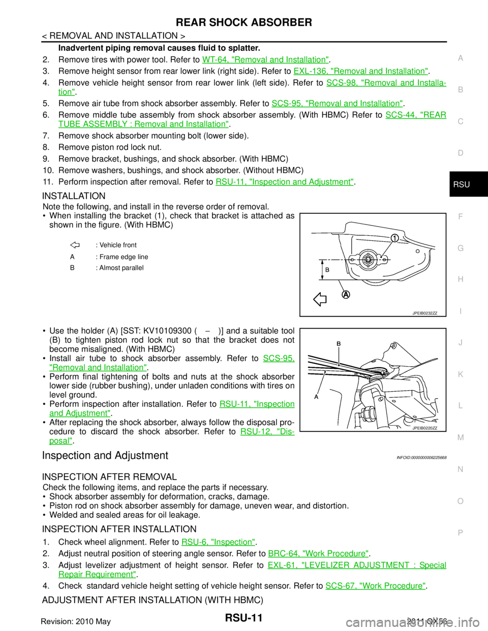
When installing the bracket (1), check that bracket is attached as
shown in the figure. (With HBMC)
Use the holder (A) [SST: KV10109300 ( −)] and a suitable tool
(B) to tighten piston rod lock nut so that the bracket does not
become misaligned. (With HBMC)
Install air tube to shock absorber assembly. Refer to SCS-95,
"Removal and Installation".
Perform final tightening of bolts and nuts at the shock absorber
lower side (rubber bushing), under unladen conditions with tires on
level ground.
Perform inspection after installation. Refer to RSU-11, "
Inspection
and Adjustment".
After replacing the shock absorber, always follow the disposal pro- cedure to discard the shock absorber. Refer to RSU-12, "
Dis-
posal".
Inspection and AdjustmentINFOID:0000000006225668
INSPECTION AFTER REMOVAL
Check the following items, and replace the parts if necessary.
Shock absorber assembly for deformation, cracks, damage.
Piston rod on shock absorber assembly for damage, uneven wear, and distortion.
Welded and sealed areas for oil leakage.
INSPECTION AFTER INSTALLATION
1. Check wheel alignment. Refer to RSU-6, "Inspection".
2. Adjust neutral position of steering angle sensor. Refer to BRC-64, "
Work Procedure".
3. Adjust levelizer adjustment of height sensor. Refer to EXL-61, "
LEVELIZER ADJUSTMENT : Special
Repair Requirement".
4. Check standard vehicle height setting of vehicle height sensor. Refer to SCS-67, "
Work Procedure".
ADJUSTMENT AFTER INSTALLATION (WITH HBMC)
: Vehicle front
A : Frame edge line
B: Almost parallel
JPEIB0232ZZ
JPEIB0220ZZ
Revision: 2010 May2011 QX56
Page 5017 of 5598
ST-30
< PERIODIC MAINTENANCE >
POWER STEERING FLUID
PERIODIC MAINTENANCE
POWER STEERING FLUID
InspectionINFOID:0000000006225597
FLUID LEVEL
1. Check fluid level with engine stopped.
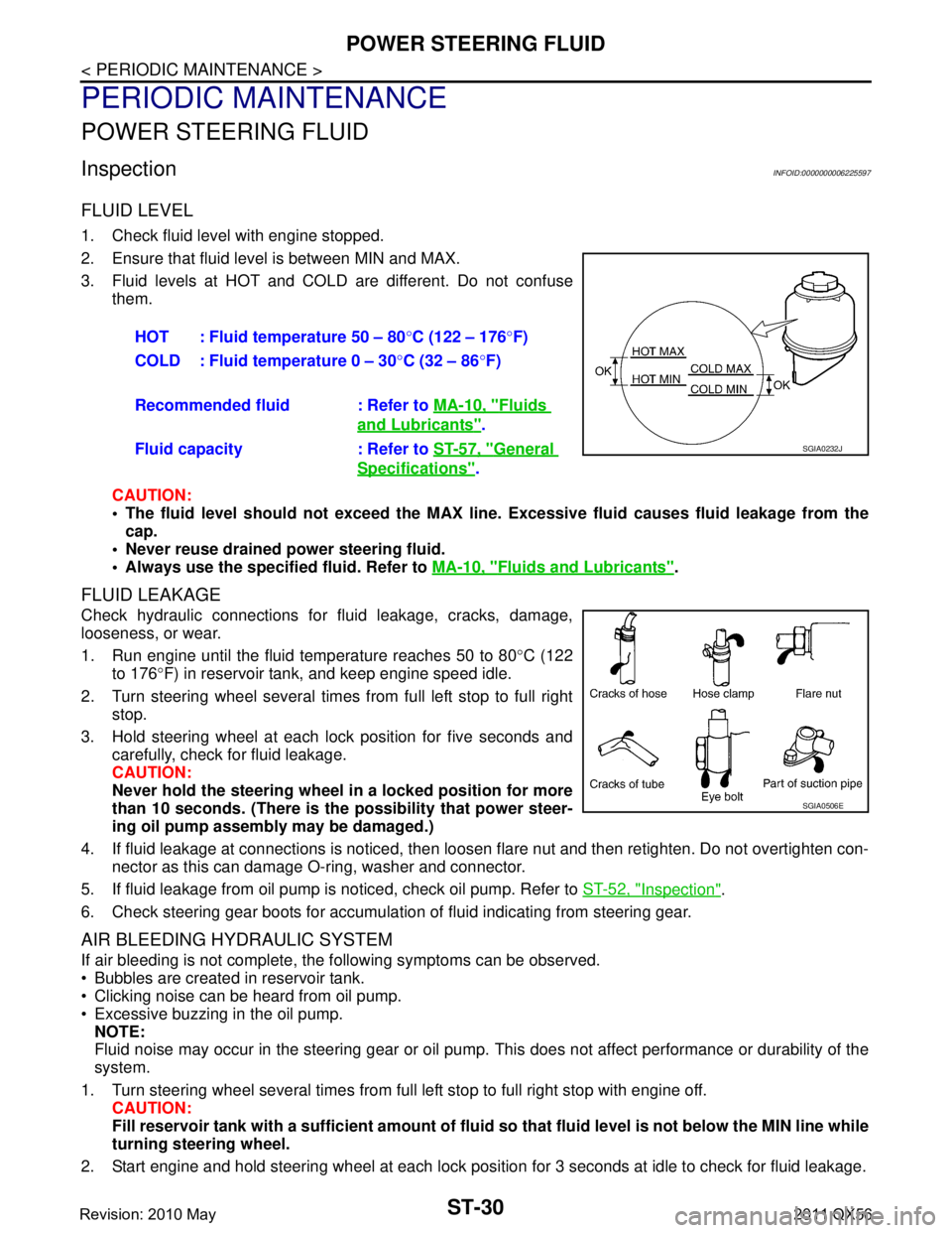
2. Ensure that fluid level is between MIN and MAX.
3. Fluid levels at HOT and COLD are different. Do not confuse
them.
CAUTION:
The fluid level should not exceed the MAX line. Excessive flui d causes fluid leakage from the
cap.
Never reuse drained power steering fluid.
Always use the specified fluid. Refer to MA-10, "
Fluids and Lubricants".
FLUID LEAKAGE
Check hydraulic connections for fluid leakage, cracks, damage,
looseness, or wear.
1. Run engine until the fluid temperature reaches 50 to 80 °C (122
to 176 °F) in reservoir tank, and keep engine speed idle.
2. Turn steering wheel several times from full left stop to full right stop.
3. Hold steering wheel at each lock position for five seconds and carefully, check for fluid leakage.
CAUTION:
Never hold the steering wheel in a locked position for more
than 10 seconds. (There is the possibility that power steer-
ing oil pump assembly may be damaged.)
4. If fluid leakage at connections is noticed, then loos en flare nut and then retighten. Do not overtighten con-
nector as this can damage O-ring, washer and connector.
5. If fluid leakage from oil pump is noticed, check oil pump. Refer to ST-52, "
Inspection".
6. Check steering gear boots for accumulation of fluid indicating from steering gear.
AIR BLEEDING HYDRAULIC SYSTEM
If air bleeding is not complete, the following symptoms can be observed.
Bubbles are created in reservoir tank.
Clicking noise can be heard from oil pump.
Excessive buzzing in the oil pump. NOTE:
Fluid noise may occur in the steering gear or oil pump. This does not affect performance or durability of the
system.
1. Turn steering wheel several times from full left stop to full right stop with engine off. CAUTION:
Fill reservoir tank with a sufficien t amount of fluid so that fluid level is not below the MIN line while
turning steering wheel.
2. Start engine and hold steering wheel at each lock position for 3 seconds at idle to check for fluid leakage.
HOT : Fluid temperature 50 – 80
°C (122 – 176 °F)
COLD : Fluid temperature 0 – 30 °C (32 – 86 °F)
Recommended fluid : Refer to MA-10, "
Fluids
and Lubricants".
Fluid capacity : Refer to ST-57, "
General
Specifications".
SGIA0232J
SGIA0506E
Revision: 2010 May2011 QX56
Page 5036 of 5598
POWER STEERING OIL PUMPST-49
< REMOVAL AND INSTALLATION >
C
DE
F
H I
J
K L
M A
B
ST
N
O P
Removal and InstallationINFOID:0000000006225612
REMOVAL
1. Drain power steering fluid from reservoir tank. CAUTION:
Never reuse drained power steering fluid.
Always use the specified fluid. Refer to MA-10, "
Fluids and Lubricants".
2. Remove the reservoir tank. Refer to CO-13, "
Removal and Installation".
3. Remove the battery and battery tray from vehicle. Refer to PG-164, "
Removal and Installation".
4. Loosen drive belt. Refer to EM-20, "
Removal and Installation".
5. Remove drive belt from oil pump pulley.
6. Remove copper washers and eye bolt (drain fluid from their pipings).
7. Remove suction hose (drain fluid from their pipings).
8. Remove oil pump mounting bolts, and then remove oil pump.
INSTALLATION
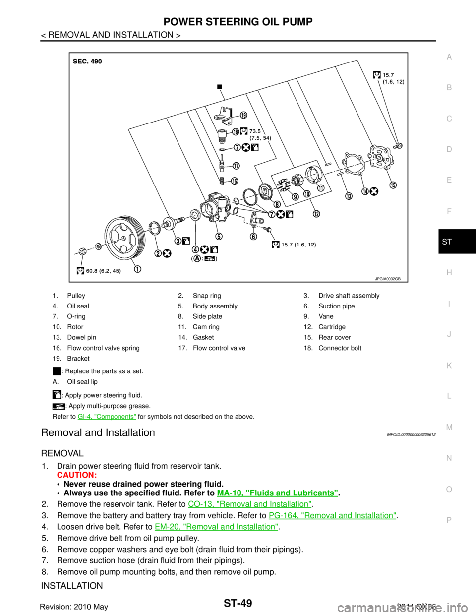
1. Pulley 2. Snap ring 3. Drive shaft assembly
4. Oil seal 5. Body assembly 6. Suction pipe
7. O-ring 8. Side plate 9. Vane
10. Rotor 11. Cam ring 12. Cartridge
13. Dowel pin 14. Gasket 15. Rear cover
16. Flow control valve spring 17. Flow control valve 18. Connector bolt
19. Bracket
: Replace the parts as a set.
A. Oil seal lip
: Apply power steering fluid.: Apply multi-purpose grease.
Refer to GI-4, "
Components" for symbols not described on the above.
JPGIA0032GB
Revision: 2010 May2011 QX56
Page 5037 of 5598
ST-50
< REMOVAL AND INSTALLATION >
POWER STEERING OIL PUMP
Note the following, and install in the reverse order of removal.
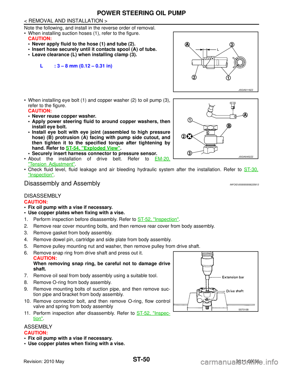
When installing suction hoses (1), refer to the figure.CAUTION:
Never apply fluid to the hose (1) and tube (2).
Insert hose securely until it contacts spool (A) of tube.
Leave clearance (L) when installing clamp (3).
When installing eye bolt (1) and copper washer (2) to oil pump (3), refer to the figure.
CAUTION:
Never reuse copper washer.
Apply power steering fluid to around copper washers, then
install eye bolt.
Install eye bolt with eye join t (assembled to high pressure
hose) (B) protrusion (A) facing with pump side cutout, and
then tighten it to the specifi ed torque after tightening by
hand. Refer to ST-54, "
Exploded View".
Securely insert harness connector to pressure sensor.
About the installation of drive belt. Refer to EM-20,
"TensionAdjustment".
Check fluid level, fluid leakage and air bleeding hydr aulic system after the installation. Refer to ST-30,
"Inspection".
Disassembly and AssemblyINFOID:0000000006225613
DISASSEMBLY
CAUTION:
Fix oil pump with a vise if necessary.
Use copper plates when fixing with a vise.
1. Perform inspection before disassembly. Refer to ST-52, "
Inspection".
2. Remove rear cover mounting bolts, and then remove rear cover from body assembly.
3. Remove gasket from body assembly.
4. Remove dowel pin, cartridge and side plate from body assembly.
5. Remove pulley mounting nut and washer, then remove pulley from drive shaft.
6. Remove snap ring from drive shaft and press out it. CAUTION:
When removing snap ring, be careful not to damage drive
shaft.
7. Remove oil seal from body assembly using a suitable tool.
8. Remove O-ring from body assembly.
9. Remove mounting bolts of suction pipe, and then remove suc- tion pipe and bracket from body assembly.
10. Remove connector bolt, and then remove O-ring, flow control
valve and spring from body assembly
11. Perform inspection after disassembly. Refer to ST-52, "
Inspec-
tion".
ASSEMBLY
CAUTION:
Fix oil pump with a vise if necessary.
Use copper plates when fixing with a vise.L : 3 – 8 mm (0.12 – 0.31 in)
JSGIA0118ZZ
JSGIA0452ZZ
SST010B
Revision: 2010 May2011 QX56
Page 5039 of 5598
ST-52
< REMOVAL AND INSTALLATION >
POWER STEERING OIL PUMP
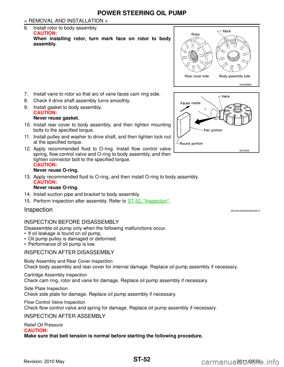
6. Install rotor to body assembly.CAUTION:
When installing rotor, turn mark face on rotor to body
assembly.
7. Install vane to rotor so that arc of vane faces cam ring side.
8. Check if drive shaft assembly turns smoothly.
9. Install gasket to body assembly. CAUTION:
Never reuse gasket.
10. Install rear cover to body assembly, and then tighten mounting bolts to the specified torque.
11. Install pulley and washer to drive shaft, and then tighten lock nut at the specified torque.
12. Apply recommended fluid to O-ring. Install flow control valve spring, flow control valve and O-ring to body assembly, and then
tighten connector bolt to the specified torque.
CAUTION:
Never reuse O-ring.
13. Apply recommended fluid to O-ring, and then install O-ring to body assembly. CAUTION:
Never reuse O-ring.
14. Install suction pipe and bracket to body assembly.
15. Perform inspection after assembly. Refer to ST-52, "
Inspection".
InspectionINFOID:0000000006225614
INSPECTION BEFORE DISASSEMBLY
Disassemble oil pump only when the following malfunctions occur.
If oil leakage is found on oil pump.
Oil pump pulley is damaged or deformed.
Performance of oil pump is low.
INSPECTION AFTER DISASSEMBLY
Body Assembly and Rear Cover Inspection
Check body assembly and rear cover for internal damage. Replace oil pump assembly if necessary.
Cartridge Assembly Inspection
Check cam ring, rotor and vane for damage. Replace oil pump assembly if necessary.
Side Plate Inspection
Check side plate for damage. Replace oil pump assembly if necessary.
Flow Control Valve Inspection
Check flow control valve and spring for damage. Replace oil pump assembly if necessary.
INSPECTION AFTER ASSEMBLY
Relief Oil Pressure
CAUTION:
Make sure that belt tension is normal before starting the following procedure.
SGIA0989E
SST843A
Revision: 2010 May2011 QX56
Page 5040 of 5598
![INFINITI QX56 2011 Factory Service Manual
POWER STEERING OIL PUMPST-53
< REMOVAL AND INSTALLATION >
C
DE
F
H I
J
K L
M A
B
ST
N
O P
1. Connect the oil pressure gauge [SST: KV48103500 (J-26357)] and the oil pressure gauge adapter [SST: KV4810 INFINITI QX56 2011 Factory Service Manual
POWER STEERING OIL PUMPST-53
< REMOVAL AND INSTALLATION >
C
DE
F
H I
J
K L
M A
B
ST
N
O P
1. Connect the oil pressure gauge [SST: KV48103500 (J-26357)] and the oil pressure gauge adapter [SST: KV4810](/manual-img/42/57033/w960_57033-5039.png)
POWER STEERING OIL PUMPST-53
< REMOVAL AND INSTALLATION >
C
DE
F
H I
J
K L
M A
B
ST
N
O P
1. Connect the oil pressure gauge [SST: KV48103500 (J-26357)] and the oil pressure gauge adapter [SST: KV48102500 (J-
33914)] between oil pump discharge connector and high-pres-
sure hose. Bleed air from the hydraulic circuit while opening
valve fully. Refer to ST-30, "
Inspection".
2. Start engine. Run engine until oil temperature reaches 50 to 80°C (122 to 176 °F).
CAUTION:
Leave the valve of the oil pressure gauge fully open while
starting and running engine. If engine is started with the
valve closed, the hydraulic pressure in oil pump goes up
to the relief pressure along with unusual increase of oil
temperature.
Be sure to keep hose clear of belts and other parts when engine is started.
3. Fully close the oil pressure gauge valve with engine at idle and measure the relief oil pressure.
CAUTION:
Never keep valve closed for 10 seconds or longer.
4. Open the valve slowly after measuring. Repair oil pump if the relief oil pressure is outside the standard. Refer to ST-50, "
Disassembly and Assembly".
5. Disconnect the oil pressure gauge from hydraulic circuit.
6. When installing eye bolt (1) and copper washer (2) to oil pump (3), refer to the figure.
CAUTION:
Never reuse copper washers.
Apply power steering fluid to around copper washer, theninstall eye bolt.
Install eye bolt with eye join t (assembled to high pressure
hose) (B) protrusion (A) facing with pump side cutout, and
then tighten it to the specifi ed torque after tightening by
hand. Refer to ST-54, "
Exploded View".
Securely insert harness connector to pressure sensor.
7. Check fluid level, fluid leakage and air bleeding hydraulic sys- tem after the installation. Refer to ST-30, "
Inspection".
Relief oil pressure : Refer to
ST-58, "
Relief Oil Pres-
sure".
SGIA1225E
JSGIA0452ZZ
Revision: 2010 May2011 QX56
Page 5095 of 5598
![INFINITI QX56 2011 Factory Service Manual
PRECAUTIONSTM-7
< PRECAUTION > [7AT: RE7R01B]
C
EF
G H
I
J
K L
M A
B
TM
N
O P
Disassembly should be done in a clean work area.
Use lint-free paper or towels for wiping parts clean. Common shop r INFINITI QX56 2011 Factory Service Manual
PRECAUTIONSTM-7
< PRECAUTION > [7AT: RE7R01B]
C
EF
G H
I
J
K L
M A
B
TM
N
O P
Disassembly should be done in a clean work area.
Use lint-free paper or towels for wiping parts clean. Common shop r](/manual-img/42/57033/w960_57033-5094.png)
PRECAUTIONSTM-7
< PRECAUTION > [7AT: RE7R01B]
C
EF
G H
I
J
K L
M A
B
TM
N
O P
Disassembly should be done in a clean work area.
Use lint-free paper or towels for wiping parts clean. Common shop rags can leave fibers that could interfere
with the operation of the transmission.
Place disassembled parts in order for easier and proper assembly.
All parts should be carefully cleaned with a general purpose, non-flammable solvent before inspection or
reassembly.
Gaskets, seals and O-rings should be repl aced any time the A/T is disassembled.
It is very important to perform func tional tests whenever they are indicated.
The valve body contains precision parts and requires extreme care when parts are removed and serviced.
Place disassembled valve body parts in order for easier and proper assembly. Care will also prevent springs
and small parts from becoming scattered or lost.
Properly installed valves, sleeves, plugs, etc. will slide along bores in valve body under their own weight.
Before assembly, apply a coat of recommended ATF to all parts. Apply petroleum jelly to protect O-rings and
seals, or hold bearings and washers in place during assembly. Never use grease.
Extreme care should be taken to avoid damage to O-rings, seals and gaskets when assembling.
When the A/T drain plug is removed, only some of the ATF is drained. Old ATF will remain in torque con- verter and ATF cooling system.
Always follow the procedures under “Changing” when changing ATF. Refer to TM-94, "
Changing".
Occasionally, the parking gear may be locked with the to rque insufficiently released, when stopping the vehi-
cle by shifting the selector lever from “D” or “R” to “P” position with the brake pedal depressed.
In this case, the shock with a thud caused by the abrupt release of torque may occur when shifting the selec-
tor lever from “P” posit ion to other positions.
However, this symptom is not a malfunction which results in the damage of parts.
Service Notice or PrecautionINFOID:0000000006274263
ATF COOLER SERVICE
If ATF contains frictional material (clutches, bands, etc. ), or if an A/T is repaired, overhauled, or replaced,
inspect and clean the A/T fluid cooler mounted in the radiat or or replace the radiator. Flush cooler lines using
cleaning solvent and compressed air after repair. For A/T fluid cooler cleaning procedure, refer to TM-97,
"Cleaning". For radiator replacement, refer to CO-13, "Exploded View".
Revision: 2010 May2011 QX56
Page 5290 of 5598
![INFINITI QX56 2011 Factory Service Manual
TM-202
< REMOVAL AND INSTALLATION >[7AT: RE7R01B]
FLUID COOLER SYSTEM
FLUID COOLER SYSTEM
Exploded ViewINFOID:0000000006226907
Removal and InstallationINFOID:0000000006226908
REMOVAL
1. Remove front INFINITI QX56 2011 Factory Service Manual
TM-202
< REMOVAL AND INSTALLATION >[7AT: RE7R01B]
FLUID COOLER SYSTEM
FLUID COOLER SYSTEM
Exploded ViewINFOID:0000000006226907
Removal and InstallationINFOID:0000000006226908
REMOVAL
1. Remove front](/manual-img/42/57033/w960_57033-5289.png)
TM-202
< REMOVAL AND INSTALLATION >[7AT: RE7R01B]
FLUID COOLER SYSTEM
FLUID COOLER SYSTEM
Exploded ViewINFOID:0000000006226907
Removal and InstallationINFOID:0000000006226908
REMOVAL
1. Remove front grille. Refer to
EXT-19, "Removal and Installation".
2. Remove reservoir tank. Refer to CO-13, "
Removal and Installation".
3. Remove radiator upper seal. Refer to DLK-220, "
Exploded View".
4. Remove air guide seal (RH). Refer to DLK-220, "
Exploded View".
5. Remove A/T fluid cooler hose C and D from A/T fluid cooler.
6. Remove liquid tank mounting bolt (A). Refer to HA-38,
"Exploded View".
7. Remove A/T fluid cooler mounting bolt (B).
8. Remove radiator mounting bolts and tilt radiator to the vehicle rear. Refer to CO-13, "
Exploded View".
9. Remove A/T fluid cooler bracket (C) from radiator (1), and remove A/T fluid cooler (2) from the vehicle.
CAUTION:
Be careful not to damage A/T fluid cooler core.
Be careful not to damage co ndenser core, condenser pipe
and liquid tank.
1. A/T assembly 2. Copper washer 3. A/T fluid cooler tube A
4. A/T fluid cooler tube D 5. Clip 6. Hose clamp
7. A/T fluid cooler hose E 8. A/T fluid cooler hose A 9. A/T fluid cooler hose B
10. A/T fluid cooler tube B 11. A/T fluid cooler tube C 12. A/T fluid cooler hose D
13. A/T fluid cooler 14. A/T fluid cooler hose C 15. A/T fluid warmer
Refer to GI-4, "
Components" for symbols in the figure.
JSDIA1595GB
JSDIA1687ZZ
Revision: 2010 May2011 QX56