2011 INFINITI QX56 service indicator
[x] Cancel search: service indicatorPage 2556 of 5598
![INFINITI QX56 2011 Factory Service Manual
EC-532
< PERIODIC MAINTENANCE >[VK56VD]
EVAP LEAK CHECK
EVAP LEAK CHECK
InspectionINFOID:0000000006267340
CAUTION:
Do not use compressed air or a high pressure pump.
Do not exceed 4.12 kPa (0.042 INFINITI QX56 2011 Factory Service Manual
EC-532
< PERIODIC MAINTENANCE >[VK56VD]
EVAP LEAK CHECK
EVAP LEAK CHECK
InspectionINFOID:0000000006267340
CAUTION:
Do not use compressed air or a high pressure pump.
Do not exceed 4.12 kPa (0.042](/manual-img/42/57033/w960_57033-2555.png)
EC-532
< PERIODIC MAINTENANCE >[VK56VD]
EVAP LEAK CHECK
EVAP LEAK CHECK
InspectionINFOID:0000000006267340
CAUTION:
Do not use compressed air or a high pressure pump.
Do not exceed 4.12 kPa (0.042 kg/cm
2, 0.6 psi) of pressure in EVAP system.
NOTE:
Do not start engine.
Improper installation of EVAP service port adapter (com mercial service tool) to the EVAP service port may
cause a leak.
WITH CONSULT-III
1. To locate the EVAP leak, install EVAP service port adapter (com- mercial service tool) and pressure pump to EVAP service port.
2. Turn ignition switch ON.
3. Select the “EVAP SYSTEM CLOSE” of “WORK SUPPORT” mode with CONSULT-III.
4. Touch “START”. A bar graph (Pressure indicating display) will appear on the screen.
5. Apply positive pressure to the EVAP system until the pressure indicator reaches the middle of the bar graph.
6. Remove EVAP service port adapter (commercial service tool) and hose with pressure pump.
7. Locate the leak using a leak detector (commercial service tool). Refer to EC-45, "
EVAPORATIVE EMISSION SYSTEM : System
Diagram".
WITHOUT CONSULT-III
1. To locate the EVAP leak, install EVAP service port adapter (com-
mercial service tool) and pressure pump to EVAP service port.
2. Apply battery voltage between the terminals of EVAP canister vent control valve to ma ke a closed EVAP system.
3. To locate the leak, deliver positive pressure to the EVAP system until pressure gauge points reach 1.38 to 2.76 kPa (0.014 to
0.028 kg/cm
2, 0.2 to 0.4 psi).
4. Remove EVAP service port adapter (commercial service tool) and hose with pressure pump.
SEF462UA
SEF200U
SEF462UA
Revision: 2010 May2011 QX56
Page 2695 of 5598

SERVICE DATA AND SPECIFICATIONS (SDS)
EM-133
< SERVICE DATA AND SPECIFICATIONS (SDS)
C
D E
F
G H
I
J
K L
M A
EM
NP
O
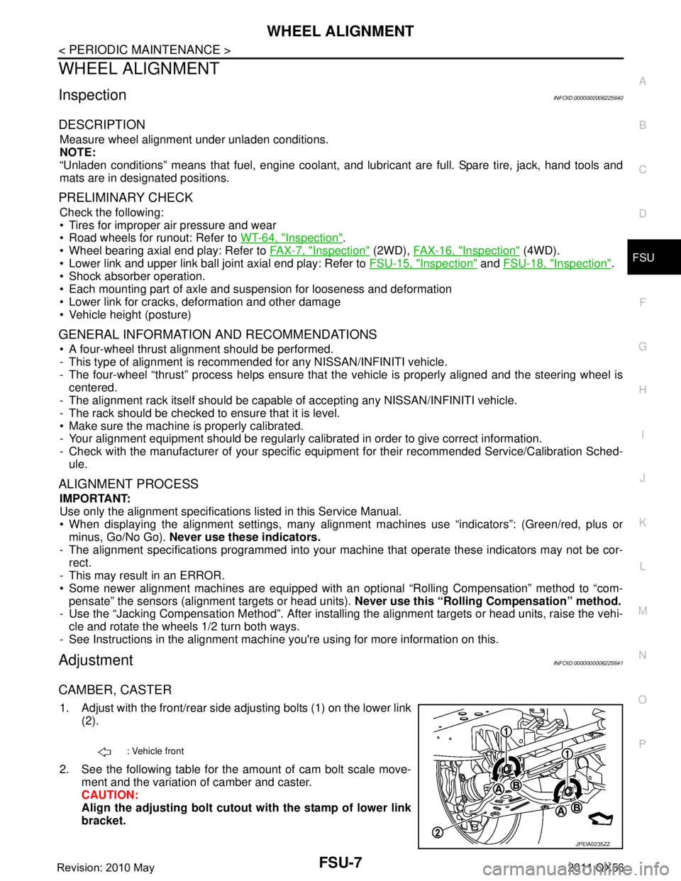
Exhaust ManifoldINFOID:0000000006289592
EXHAUST MANIFOLD
Unit: mm (in)
CamshaftINFOID:0000000006289593
EXHAUST CAMSHAFT
Unit: mm (in)
*: Total indicator reading
INTAKE CAMSHAFT
Unit: mm (in)
*1: Total indicator reading
VA LV E L I F T E R
Unit: mm (in)
VALVE CLEARANCE
Gap
Standard 1.1 (0.043)
Limit 1.25 (0.049)
Items Limit
Surface distortion Exhaust manifold 0.7 (0.028)
Items Standard Limit
Exhaust camshaft journal oil clearance 0.030 - 0.071 (0.0012 - 0.0028) 0.150 (0.0059)
VVEL ladder asse mbly bracket inner diameter (EXH side) 26.000 - 26.021 (1.0236 - 1.0244) —
Exhaust camshaft journal diameter 25.935 - 25.955 (1.0211 - 1.0218) —
Exhaust camshaft end play 0.115 - 0.188 (0.0045 - 0.0074) 0.24 (0.0094)
Exhaust camshaft cam height “A” 45.475 - 45.665 (1.7904 - 1.7978) 45.275 (1.7825)
Exhaust camshaft runout [TIR*] Less than 0.02 (0.0008) 0.05 (0.002)
Exhaust camshaft sprocket runout [TIR*] — 0.2 (0.0079)
SEM671
Items Standard Limit
Drive shaft end play 0.115 - 0.188 (0.0045 - 0.0074) 0.24 (0.0094)
Intake camshaft sprocket runout [TIR*
1] — 0.15 (0.0059)
Items Standard
Valve lifter outer diameter 33.980 - 33.990 (1.3378 - 1.3382)
Valve lifter hole diameter 34.000 - 34.016 (1.3386 - 1.3392)
Valve lifter clearance 0.010 - 0.036 (0.0004 - 0.0014)
Revision: 2010 May2011 QX56
Page 2703 of 5598

SERVICE DATA AND SPECIFICATIONS (SDS)
EM-141
< SERVICE DATA AND SPECIFICATIONS (SDS)
C
D E
F
G H
I
J
K L
M A
EM
NP
O
*: Total indicator reading
Main BearingINFOID:0000000006289596
MAIN BEARING
UNDERSIZE
Unit: mm (in)
MAIN BEARING OIL CLEARANCE
Center distance “r”
45.96 - 46.04 (1.8095 - 1.8126)
Ta p e r Limit 0.0025 (0.0001)
Out-of-round 0.0025 (0.0001)
Crankshaft runout [TIR*] Standard Less than 0.05 (0.002)
Limit 0.10 (0.0039)
Crankshaft end play Standard 0.10 - 0.26 (0.0039 - 0.0102)
Limit 0.30 (0.012)
Grade number Thickness mm (in) Width mm (in) Identification color Remarks
0 2.483 - 2.486 (0.0978 - 0.0979)
19.9 - 20.1
(0.783 - 0.791) Black
Grade is the same
for upper and lower
bearings.
1 2.486 - 2.489 (0.0979 - 0.0980) Brown
2 2.489 - 2.492 (0.0980 - 0.0981) Green
3 2.492 - 2.495 (0.0981 - 0.0982) Yellow
4 2.495 - 2.498 (0.0982 - 0.0983) Blue
5 2.498 - 2.501 (0.0983 - 0.0985) Pink
6 2.501 - 2.504 (0.0985 - 0.0986) Purple
7 2.504 - 2.507 (0.0986 - 0.0987) White
8 2.507 - 2.510 (0.0987 - 0.0988) Red
01 UPR 2.483 - 2.486 (0.0978 - 0.0979) Black
Grade and color are
different for upper
and lower bearings.
LWR 2.486 - 2.489 (0.0979 - 0.0980) Brown
12 UPR 2.486 - 2.489 (0.0979 - 0.0980) Brown
LWR 2.489 - 2.492 (0.0980 - 0.0981) Green
23 UPR 2.489 - 2.492 (0.0980 - 0.0981) Green
LWR 2.492 - 2.495 (0.0981 - 0.0982) Yellow
34 UPR 2.492 - 2.495 (0.0981 - 0.0982) Yellow
LWR 2.495 - 2.498 (0.0982 - 0.0983) Blue
45 UPR 2.495 - 2.498 (0.0982 - 0.0983) Blue
LWR 2.498 - 2.501 (0.0983 - 0.0985) Pink
56 UPR 2.498 - 2.501 (0.0983 - 0.0985) Pink
LWR 2.501 - 2.504 (0.0985 - 0.0986) Purple
67 UPR 2.501 - 2.504 (0.0985 - 0.0986) Purple
LWR 2.504 - 2.507 (0.0986 - 0.0987) White
78 UPR 2.504 - 2.507 (0.0986 - 0.0987) White
LWR 2.507 - 2.510 (0.0987 - 0.0988) Red
Items Thickness Main journal diameter
0.25 (0.0098) 2.618 - 2.626 (0.1031 - 0.1034) Grind so that bearing clearance is the specified value.
Revision: 2010 May2011 QX56
Page 2742 of 5598
![INFINITI QX56 2011 Factory Service Manual
EXL-32
< SYSTEM DESCRIPTION >[XENON TYPE]
DIAGNOSIS SYSTEM (AFS)
DIAGNOSIS SYSTEM (AFS)
CONSULT-III Function (ADAPTIVE LIGHT)INFOID:0000000006213915
APPLICATION ITEM
WORK SUPPORT
*: Adjusts the steer INFINITI QX56 2011 Factory Service Manual
EXL-32
< SYSTEM DESCRIPTION >[XENON TYPE]
DIAGNOSIS SYSTEM (AFS)
DIAGNOSIS SYSTEM (AFS)
CONSULT-III Function (ADAPTIVE LIGHT)INFOID:0000000006213915
APPLICATION ITEM
WORK SUPPORT
*: Adjusts the steer](/manual-img/42/57033/w960_57033-2741.png)
EXL-32
< SYSTEM DESCRIPTION >[XENON TYPE]
DIAGNOSIS SYSTEM (AFS)
DIAGNOSIS SYSTEM (AFS)
CONSULT-III Function (ADAPTIVE LIGHT)INFOID:0000000006213915
APPLICATION ITEM
WORK SUPPORT
*: Adjusts the steering angle sensor neutral position on ABS actuator and electrical unit (control unit) side. Refer to
BRC-64, "Work Pro-
cedure".
DATA MONITOR
*: The swivel angle "0°" (feedback value) of the swivel position sensor signal may differ from the swivel angle "0 °" of the swivel motor
(AFS control unit command value). This causes that the swivel motor initializes the value based on the step number from the sto pper.
ACTIVE TEST
Diagnostic mode Description
Ecu Identification Allows confirmation of AFS control unit part number.
Self Diagnostic Result Displays the diagnosis results judged by AFS control unit.
Work support Sets each sensor.
Data monitor Indicates AFS control unit input data in real time.
Active test Provides the drive signal to the load. Checks operation.
Service item Description
ST ANG SEN ADJUSTMENT
*—
LEVELIZER ADJUSTMENT Adjusts the height sensor signal output value (AFS control unit recognized) in the un-
loaded vehicle condition.
Monitor item
[Unit] Description
STR ANGLS SIG
[deg] The steering angle value judged by the steering angle sensor signal received from
the steering angle sensor via CAN communication
VHCL SPD
[km/h] The vehicle speed signal value from the combination meter via CAN communication
SLCT LVR POSI
[P/R/N/D/M/FF] The selector lever status judged by the position indicator signal received from TCM
via CAN communication
HEAD LAMP
[On/Off] The headlamp On/Off status judged by the low beam headlamp (ON) signal received
from IPDM E/R via
CAN communication
AFS SW
[On/Off] The AFS On/Off status judged by AFS control unit
HI SEN OTP RR
[V] The rear height sensor signal voltage value input from the rear height sensor
HI SEN OTP FR
[V] The front height sensor signal voltage value input from the front height sensor
LEV ACTR VLTG
[%] The ratio value to the battery voltage generated by the levelizer activation signal con-
trol value judged by AFS control unit
SWVL SEN RH
*
[deg] The head lamp swivel angle value judged by AFS control unit received from the swiv-
el position sensor signal input from the swivel actuator
SWVL SEN LH
*
[deg]
SWVL ANGLE RH
*
[deg]
The swivel angle command value to the swivel motor judged by AFS control unit
SWVL ANGLE LH
*
[deg]
Revision: 2010 May2011 QX56
Page 2949 of 5598

WHEEL ALIGNMENTFSU-7
< PERIODIC MAINTENANCE >
C
DF
G H
I
J
K L
M A
B
FSU
N
O P
WHEEL ALIGNMENT
InspectionINFOID:0000000006225640
DESCRIPTION
Measure wheel alignment under unladen conditions.
NOTE:
“Unladen conditions” means that fuel, engine coolant, and lubricant are full. Spare tire, jack, hand tools and
mats are in designated positions.
PRELIMINARY CHECK
Check the following:
Tires for improper air pressure and wear
Road wheels for runout: Refer to WT-64, "
Inspection".
Wheel bearing axial end play: Refer to FA X - 7 , "
Inspection" (2WD), FAX-16, "Inspection" (4WD).
Lower link and upper link ball joint axial end play: Refer to FSU-15, "
Inspection" and FSU-18, "Inspection".
Shock absorber operation.
Each mounting part of axle and suspension for looseness and deformation
Lower link for cracks, deformation and other damage
Vehicle height (posture)
GENERAL INFORMATION AND RECOMMENDATIONS
A four-wheel thrust alignment should be performed.
- This type of alignment is recomm ended for any NISSAN/INFINITI vehicle.
- The four-wheel “thrust” process helps ensure that t he vehicle is properly aligned and the steering wheel is
centered.
- The alignment rack itself should be capable of accepting any NISSAN/INFINITI vehicle.
- The rack should be checked to ensure that it is level.
Make sure the machine is properly calibrated.
- Your alignment equipment should be regularly ca librated in order to give correct information.
- Check with the manufacturer of your specific equi pment for their recommended Service/Calibration Sched-
ule.
ALIGNMENT PROCESS
IMPORTANT:
Use only the alignment specificati ons listed in this Service Manual.
When displaying the alignment settings, many alignment machines use “indicators”: (Green/red, plus or
minus, Go/No Go). Never use these indicators.
- The alignment specifications programmed into your machine that operate these indicators may not be cor-
rect.
- This may result in an ERROR.
Some newer alignment machines are equipped with an optional “Rolling Compensation” method to “com-
pensate” the sensors (alignment targets or head units). Never use this “Rolling Compensation” method.
- Use the “Jacking Compensation Method”. After installi ng the alignment targets or head units, raise the vehi-
cle and rotate the wheels 1/2 turn both ways.
- See Instructions in the alignment machine you're using for more information on this.
AdjustmentINFOID:0000000006225641
CAMBER, CASTER
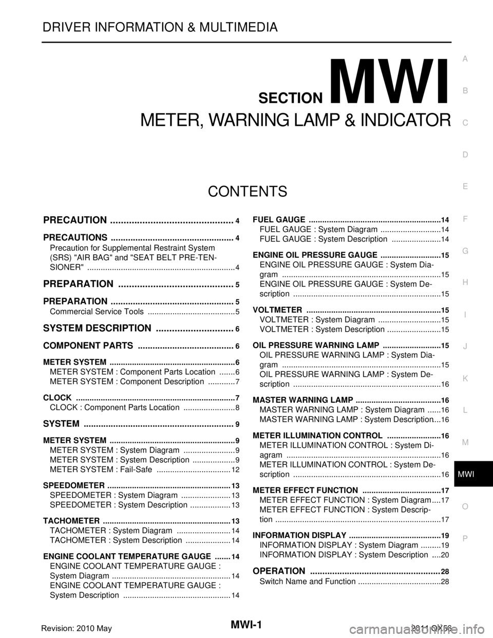
1. Adjust with the front/rear side adjusting bolts (1) on the lower link
(2).
2. See the following table for the amount of cam bolt scale move- ment and the variation of camber and caster.
CAUTION:
Align the adjusting bolt cutout with the stamp of lower link
bracket.
: Vehicle front
JPEIA0235ZZ
Revision: 2010 May2011 QX56
Page 3744 of 5598

MWI
MWI-1
DRIVER INFORMATION & MULTIMEDIA
C
DE
F
G H
I
J
K L
M B
SECTION MWI
A
O P
CONTENTS
METER, WARNING LAMP & INDICATOR
PRECAUTION ................ ...............................4
PRECAUTIONS .............................................. .....4
Precaution for Supplemental Restraint System
(SRS) "AIR BAG" and "SEAT BELT PRE-TEN-
SIONER" ............................................................. ......
4
PREPARATION ............................................5
PREPARATION .............................................. .....5
Commercial Service Tools .................................. ......5
SYSTEM DESCRIPTION ..............................6
COMPONENT PARTS ................................... .....6
METER SYSTEM .........................................................6
METER SYSTEM : Component Parts Location .. ......6
METER SYSTEM : Component Description .............7
CLOCK .................................................................. ......7
CLOCK : Component Parts Location ........................8
SYSTEM ..............................................................9
METER SYSTEM .........................................................9
METER SYSTEM : System Diagram ........................9
METER SYSTEM : System Description ....................9
METER SYSTEM : Fail-Safe ..................................12
SPEEDOMETER ................ ........................................13
SPEEDOMETER : System Diagram ................... ....13
SPEEDOMETER : System Description ...................13
TACHOMETER ...................................................... ....13
TACHOMETER : System Diagram .........................14
TACHOMETER : System Description .....................14
ENGINE COOLANT TEMPERATURE GAUGE .... ....14
ENGINE COOLANT TEMPERATURE GAUGE :
System Diagram ......................................................
14
ENGINE COOLANT TEMPERATURE GAUGE :
System Description .................................................
14
FUEL GAUGE ........................................................ ....14
FUEL GAUGE : System Diagram ............................14
FUEL GAUGE : System Description .......................14
ENGINE OIL PRESSURE GAUGE ............................15
ENGINE OIL PRESSURE GAUGE : System Dia-
gram .................................................................... ....
15
ENGINE OIL PRESSURE GAUGE : System De-
scription ...................................................................
15
VOLTMETER ......................................................... ....15
VOLTMETER : System Diagram .............................15
VOLTMETER : System Description .........................15
OIL PRESSURE WARNING LAMP ...........................15
OIL PRESSURE WARNING LAMP : System Dia-
gram .................................................................... ....
15
OIL PRESSURE WARNING LAMP : System De-
scription ...................................................................
16
MASTER WARNING LAMP ................................... ....16
MASTER WARNING LAMP : System Diagram .......16
MASTER WARNING LAMP : System Description ....16
METER ILLUMINATION CONTROL ..................... ....16
METER ILLUMINATION CONTROL : System Di-
agram ......................................................................
16
METER ILLUMINATION CONTROL : System De-
scription ...................................................................
16
METER EFFECT FUNCTION ................................ ....17
METER EFFECT FUNCTION : System Diagram ....17
METER EFFECT FUNCTION : System Descrip-
tion ...........................................................................
17
INFORMATION DISPLAY ...................................... ....19
INFORMATION DISPLAY : System Diagram ..........19
INFORMATION DISPLAY : System Description .....20
OPERATION .....................................................28
Switch Name and Function ......................................28
Revision: 2010 May2011 QX56
Page 4261 of 5598

RSU-6
< PERIODIC MAINTENANCE >
WHEEL ALIGNMENT
WHEEL ALIGNMENT
InspectionINFOID:0000000006225661
DESCRIPTION
Measure wheel alignment under unladen conditions.
NOTE:
“Unladen conditions” means that fuel, engine coolant, and lubricant are full. Spare tire, jack, hand tools and
mats are in designated positions.
PRELIMINARY CHECK
Check the following:
Tires for improper air pressure and wear
Road wheels for runout. Refer to WT-64, "
Inspection".
Wheel bearing axial end play. Refer to RAX-5, "
Inspection".
Ball joint axial end play of suspension arm and front lower link. Refer to RSU-20, "
Ball Joint".
Shock absorber operation
Each mounting point of axle and suspension for looseness and deformation
Each of front lower link, rear lower link, rear suspension member, suspension arm and shock absorber for
cracks, deformation, and other damage
Vehicle height (posture)
GENERAL INFORMATION AND RECOMMENDATIONS
A four-wheel thrust alignment should be performed.
- This type of alignment is recomm ended for any NISSAN/INFINITI vehicle.
- The four-wheel “thrust” process helps ensure that t he vehicle is properly aligned and the steering wheel is
centered.
- The alignment rack itself should be capable of accepting any NISSAN/INFINITI vehicle.
- The rack should be checked to ensure that it is level.
Make sure the machine is properly calibrated.
- Your alignment equipment should be regularly calib rated in order to give correct information.
- Check with the manufacturer of your specific equi pment for their recommended Service/Calibration Sched-
ule.
ALIGNMENT PROCESS
IMPORTANT:
Use only the alignment specifications listed in this Service Manual.
When displaying the alignment settings, many alignment machines use “indicators”: (Green/red, plus or
minus, Go/No Go). Never use these indicators.
- The alignment specifications programmed into your machine that operate these indicators may not be cor-
rect.
- This may result in an ERROR.
Some newer alignment machines are equipped with an optional “Rolling Compensation” method to “com- pensate” the sensors (alignment targets or head units). Never use this “Rolling Compensation” method.
- Use the “Jacking Compensation Method”. After installi ng the alignment targets or head units, raise the vehi-
cle and rotate the wheels 1/2 turn both ways.
- See Instructions in the alignment machine you're using for more information on this.
AdjustmentINFOID:0000000006225662
CAMBER
Revision: 2010 May2011 QX56
Page 4634 of 5598
![INFINITI QX56 2011 Factory Service Manual
DIAGNOSIS SYSTEM (BCM)SEC-27
< SYSTEM DESCRIPTION > [WITH INTELLIGENT KEY SYSTEM]
C
D
E
F
G H
I
J
L
M A
B
SEC
N
O P
ACTIVE TEST
IMMU
IMMU : CONSULT-III Function (BCM - IMMU)INFOID:0000000006226190
DA INFINITI QX56 2011 Factory Service Manual
DIAGNOSIS SYSTEM (BCM)SEC-27
< SYSTEM DESCRIPTION > [WITH INTELLIGENT KEY SYSTEM]
C
D
E
F
G H
I
J
L
M A
B
SEC
N
O P
ACTIVE TEST
IMMU
IMMU : CONSULT-III Function (BCM - IMMU)INFOID:0000000006226190
DA](/manual-img/42/57033/w960_57033-4633.png)
DIAGNOSIS SYSTEM (BCM)SEC-27
< SYSTEM DESCRIPTION > [WITH INTELLIGENT KEY SYSTEM]
C
D
E
F
G H
I
J
L
M A
B
SEC
N
O P
ACTIVE TEST
IMMU
IMMU : CONSULT-III Function (BCM - IMMU)INFOID:0000000006226190
DATA MONITOR
ACTIVE TEST
WORK SUPPORT
Service Item Description
SECURITY ALARM SET This mode is able to confirm and change security alarm ON-OFF setting.
THEFT ALM TRG The switch which triggered vehicle security alarm is recorded.
This mode is able to confirm and erase the record of vehicle security alarm.
The trigger data can be erased by touching “CLEAR” on CONSULT-III screen.
Test Item Description
THEFT IND This test is able to check security indicator lamp operation. Security indicator lamp is turned on
when “ON” on CONSULT-III screen is touched.
VEHICLE SECURITY HORN This test is able to check horn operation. Horn is activated for 0.5 seconds after “ON” on CONSULT-
III screen is touched.
HEADLAMP(HI) This test is able to check headlamp operation. Headlamps are activated for 0.5 seconds after “ON”
on CONSULT-III screen is touched.
FLASHER This test is able to check hazard warning lamp operation. Hazard warning lamps are activated after
“ON” on CONSULT-III screen is touched.
Monitor item Content
CONFRM ID ALL
Indicates [YET] at all time.
Switches to [DONE] when a registered Intelligent Key backside is contacted to push-button ignition
switch.
CONFIRM ID4
CONFIRM ID3
CONFIRM ID2
CONFIRM ID1
NOT REGISTERED
Indicates [ID OK] when key ID that is registered is received or is not yet received.
Indicates [ID NG] when key ID that is not registered is received.
TP 4
Indicates the number of IDs that are registered.
TP 3
TP 2
TP 1
PUSH SW Indicates [ON/OFF] condition of push-button ignition switch.
Test item Description
THEFT IND This test is able to check security indicator lamp operation.
Security indicator lamp is turned on when “ON” on CONSULT-III screen touched.
Service item Description
CONFIRM DONGLE ID It is possible to check that dongle unit is applied to the vehicle.
Revision: 2010 May2011 QX56