2011 INFINITI QX56 radiator cap
[x] Cancel search: radiator capPage 2552 of 5598
![INFINITI QX56 2011 Factory Service Manual
E C -528
< SYMPTOM DIAGNOSIS >[VK56VD]
ENGINE CONTROL SYSTEM SYMPTOMS
1 - 6: The numbers refer to the order of inspection.Lubrica-
tion
Oil pan/Oil strainer/Oil pump/Oil
filter/Oil gallery/Oil coole INFINITI QX56 2011 Factory Service Manual
E C -528
< SYMPTOM DIAGNOSIS >[VK56VD]
ENGINE CONTROL SYSTEM SYMPTOMS
1 - 6: The numbers refer to the order of inspection.Lubrica-
tion
Oil pan/Oil strainer/Oil pump/Oil
filter/Oil gallery/Oil coole](/manual-img/42/57033/w960_57033-2551.png)
E C -528
< SYMPTOM DIAGNOSIS >[VK56VD]
ENGINE CONTROL SYSTEM SYMPTOMS
1 - 6: The numbers refer to the order of inspection.Lubrica-
tion
Oil pan/Oil strainer/Oil pump/Oil
filter/Oil gallery/Oil cooler 55555 55 5 EM-56
EM-60
LU-9
LU-12
LU-14
Oil level (Low)/Filthy oil
LU-7
Cooling
Radiator/Hose/Radiator filler cap
55555 55 45 CO-11
CO-11
Thermostat 5
CO-21
Water pumpCO-19
Water galleryEM-115
Cooling fan
5CO-17
Coolant level (Low)/Contaminat-
ed coolant
CO-8
IVIS (INFINITI Vehicle Immobilizer System —
NATS)11
SEC-48
SYMPTOM
Reference
page
HARD/NO START/RESTART (EXCP. HA)
ENGINE STALL
HESITATION/SURGING/FLAT SPOT
SPARK KNOCK/DETONATION
LACK OF POWER/POOR ACCELERATION
HIGH IDLE/LOW IDLE
ROUGH IDLE/HUNTING
IDLING VIBRATION
SLOW/NO RETURN TO IDLE
OVERHEATS/WATER TEMPERATURE HIGH
EXCESSIVE FUEL CONSUMPTION
EXCESSIVE OIL CONSUMPTION
BATTERY DEAD (UNDER CHARGE)
Warranty symptom code AA AB AC AD AE AF AG AH AJ AK AL AM HA
Revision: 2010 May2011 QX56
Page 2992 of 5598
GI-28
< PRECAUTION >
PRECAUTIONS
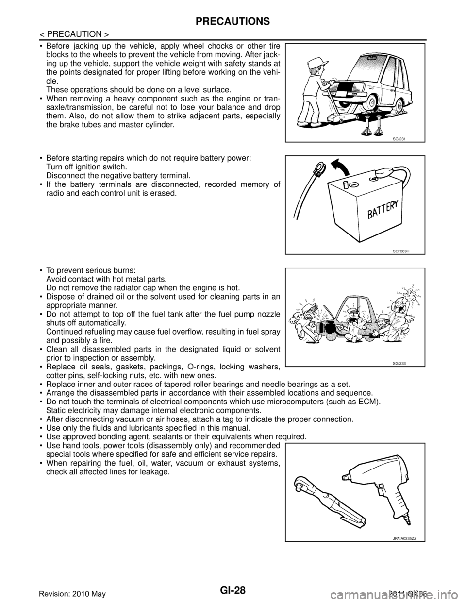
Before jacking up the vehicle, apply wheel chocks or other tireblocks to the wheels to prevent t he vehicle from moving. After jack-
ing up the vehicle, support the vehicle weight with safety stands at
the points designated for proper lifting before working on the vehi-
cle.
These operations should be done on a level surface.
When removing a heavy component such as the engine or tran- saxle/transmission, be careful not to lose your balance and drop
them. Also, do not allow them to strike adjacent parts, especially
the brake tubes and master cylinder.
Before starting repairs which do not require battery power: Turn off ignition switch.
Disconnect the negative battery terminal.
If the battery terminals are disconnected, recorded memory of
radio and each control unit is erased.
To prevent serious burns: Avoid contact with hot metal parts.
Do not remove the radiator cap when the engine is hot.
Dispose of drained oil or the solvent used for cleaning parts in an appropriate manner.
Do not attempt to top off the fuel tank after the fuel pump nozzle
shuts off automatically.
Continued refueling may cause fuel overflow, resulting in fuel spray
and possibly a fire.
Clean all disassembled parts in the designated liquid or solvent prior to inspection or assembly.
Replace oil seals, gaskets, packings, O-rings, locking washers,
cotter pins, self-locking nuts, etc. with new ones.
Replace inner and outer races of tapered roller bearings and needle bearings as a set.
Arrange the disassembled parts in accordance with their assembled locations and sequence.
Do not touch the terminals of electrical com ponents which use microcomputers (such as ECM).
Static electricity may damage internal electronic components.
After disconnecting vacuum or air hoses, atta ch a tag to indicate the proper connection.
Use only the fluids and lubricants specified in this manual.
Use approved bonding agent, sealants or their equivalents when required.
Use hand tools, power tools (disassembly only) and recommended special tools where specified for safe and efficient service repairs.
When repairing the fuel, oil, water, vacuum or exhaust systems, check all affected lines for leakage.
SGI231
SEF289H
SGI233
JPAIA0335ZZ
Revision: 2010 May2011 QX56
Page 3094 of 5598
HA-38
< REMOVAL AND INSTALLATION >
CONDENSER
CONDENSER
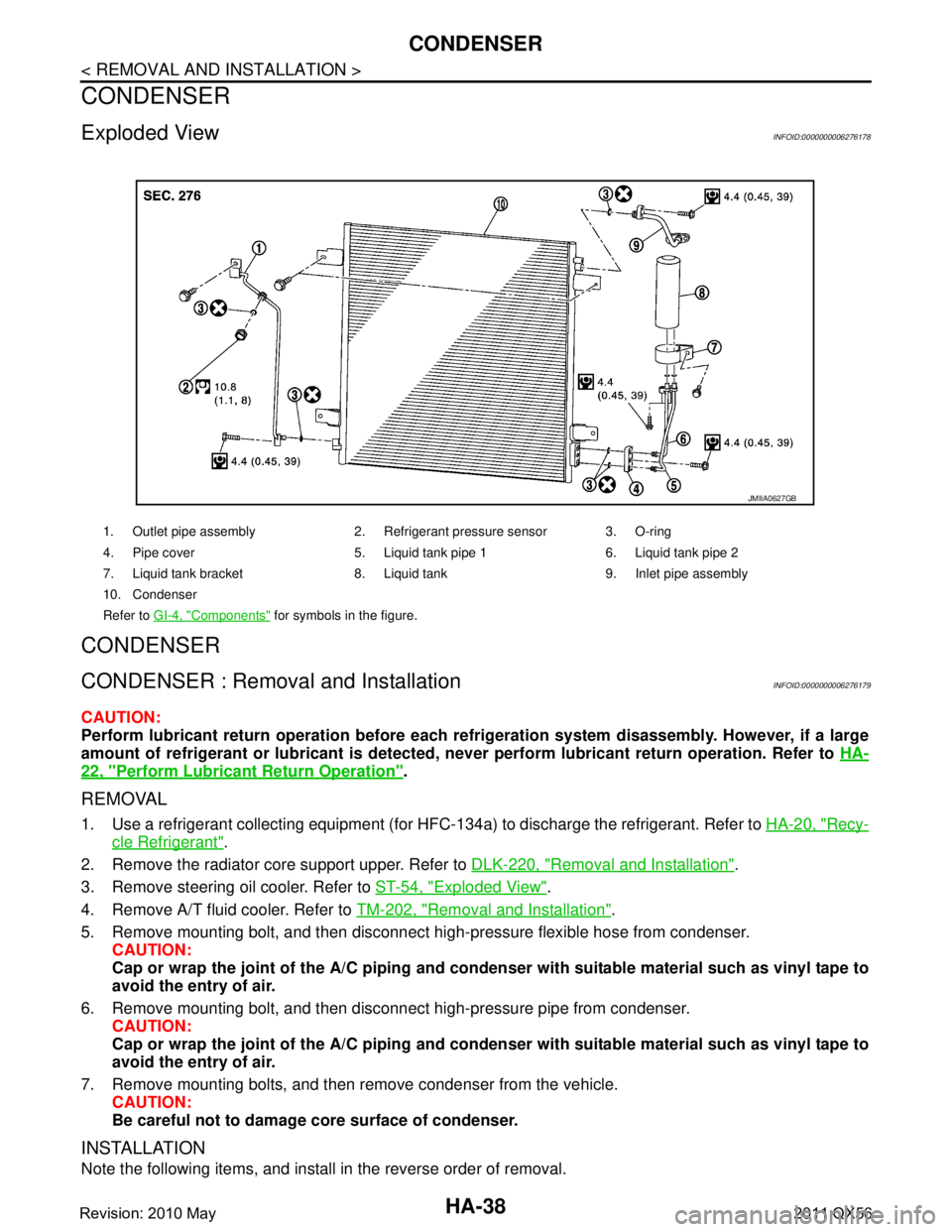
Exploded ViewINFOID:0000000006276178
CONDENSER
CONDENSER : Removal and InstallationINFOID:0000000006276179
CAUTION:
Perform lubricant return operation before each refrigeration system disassembly. However, if a large
amount of refrigerant or lubrican t is detected, never perform lubricant return operation. Refer to HA-
22, "Perform Lubricant Return Operation".
REMOVAL
1. Use a refrigerant collecting equipment (for HF C-134a) to discharge the refrigerant. Refer to HA-20, "Recy-
cle Refrigerant".
2. Remove the radiator core support upper. Refer to DLK-220, "
Removal and Installation".
3. Remove steering oil cooler. Refer to ST-54, "
Exploded View".
4. Remove A/T fluid cooler. Refer to TM-202, "
Removal and Installation".
5. Remove mounting bolt, and then disconnect high-pressure flexible hose from condenser. CAUTION:
Cap or wrap the joint of the A/C piping and conden ser with suitable material such as vinyl tape to
avoid the entry of air.
6. Remove mounting bolt, and then disconnect high-pressure pipe from condenser. CAUTION:
Cap or wrap the joint of the A/C piping and conden ser with suitable material such as vinyl tape to
avoid the entry of air.
7. Remove mounting bolts, and then remove condenser from the vehicle. CAUTION:
Be careful not to damage core surface of condenser.
INSTALLATION
Note the following items, and install in the reverse order of removal.
1. Outlet pipe assembly 2. Refrigerant pressure sensor 3. O-ring
4. Pipe cover 5. Liquid tank pipe 1 6. Liquid tank pipe 2
7. Liquid tank bracket 8. Liquid tank 9. Inlet pipe assembly
10. Condenser
Refer to GI-4, "
Components" for symbols in the figure.
JMIIA0627GB
Revision: 2010 May2011 QX56
Page 3099 of 5598
A/C UNIT ASSEMBLYHA-43
< REMOVAL AND INSTALLATION >
C
DE
F
G H
J
K L
M A
B
HA
N
O P
Perform lubricant return operati on before each refrigeration system disassembly. However, if a large
amount of refrigerant or lubricant is detected, n ever perform lubricant return operation. Refer to HA-
22, "Perform Lubricant Return Operation".
REMOVAL
1. Use a refrigerant collecting equipment (for HF C-134a) to discharge the refrigerant. Refer to HA-20, "Recy-
cle Refrigerant". (If equipped)
2. Drain engine coolant from cooling system. Refer to CO-8, "
Draining".
3. Remove clamps, and then disconnect front heater outlet hose from heater pipe.
CAUTION:
Some coolant may spill when heater hoses are disconnected.
Close off the coolant inlet and outlet on the heater core (2 locations) with shop cloths.
4. Remove mounting bolt, and then disconnect low-pressure pipe and high-pressure pipe from expansion valve.
CAUTION:
Cap or wrap the joint of the A/C piping and expan sion valve with suitable material such as vinyl
tape to avoid the entry of air.
5. Remove instrument panel assembly. Refer to IP-14, "
Removal and Installation".
6. Remove steering column mounting bolt and nuts. Refer to ST-34, "
Removal and Installation".
7. Move steering column assembly to a position where it does not inhibit work.
8. Disconnect harness clips, harness connectors, ground bol ts and blackets from steering member, and then
move the vehicle harness to the position without hindrance for work.
9. Remove mounting nuts, and then remove instrument stay (RH and LH).
10. Remove A/C unit assembly mounting bolts.
11. Remove mounting bolts, and then remove steering member from the vehicle.
12. Disconnect drain hose from A/C unit assembly, and then remove A/C unit assembly from the vehicle.
13. Remove mounting bolts, and then disconnect heater & cooling unit and blower unitassembly.
INSTALLATION
Note the following items, and install in the reverse order of removal.
CAUTION:
Replace O-rings with new ones. Then apply compressor oil to them when installing.
Check for leakages when recharging refrigerant. Refer to HA-18, "
Leak Test".
NOTE:
Refer to CO-9, "
Refilling" when filling radiator with engine coolant.
EVAPORATOR
EVAPORATOR : Removal and InstallationINFOID:0000000006276184
REMOVAL
1. Remove heater & cooling unit assembly. Refer to HA-41, "Exploded View".
2. Remove heater core. Refer to HA-44, "
HEATER CORE : Removal and Installation".
3. Remove mounting screws, and then remove evaporator pipe cover.
4. Remove air mix door motor (RH). Refer to HAC-153, "
AIR MIX DOOR MOTOR : Removal and Installa-
tion".
5. Remove mounting screws, and then remove A/C cover.
6. Remove foot duct LH. Refer to VTL-11, "
FLOOR DUCT 1 : Removal and Installation".
7. Remove mounting screws, and then remove A/C lower case.
8. Remove intake sensor. Refer to HAC-150, "
Removal and Installation".
9. Remove evaporator assembly from heater & cooling unit assembly.
10. Remove mounting bolts, and then remove evaporator from evaporator assembly.
CAUTION:
Cap or wrap the joint of the evaporator and evaporat or pipe assembly with suitable material such as
vinyl tape to avoid the entry of air.
Revision: 2010 May2011 QX56
Page 3671 of 5598
MA-1
MAINTENANCE
C
DE
F
G H
I
J
K L
M B
MA
SECTION MA
N
O A
CONTENTS
MAINTENANCE
PREPARATION .............
...............................3
PREPARATION .............................................. .....3
Special Service Tool ........................................... ......3
Commercial Service Tool ..........................................3
PERIODIC MAINTENANCE ..........................4
GENERAL MAINTENANCE ........................... .....4
Explanation of General Maintenance .................. ......4
PERIODIC MAINTENANCE ................................6
Introduction of Periodic Maintenance .................. ......6
Schedule 1 ................................................................6
Schedule 2 ................................................................8
RECOMMENDED FLUIDS AND LUBRI-
CANTS ................................................................
10
Fluids and Lubricants .......................................... ....10
Engine Oil Recommendation ..................................10
Anti-Freeze Coolant Mixture Ratio ..........................11
ENGINE MAINTENANCE ...................................12
DRIVE BELTS ....................................................... ....12
DRIVE BELTS : Exploded View ..............................12
DRIVE BELTS : Checking .......................................12
DRIVE BELTS : Tension Adjustment .....................12
ENGINE COOLANT ............................................... ....12
ENGINE COOLANT : Inspection .............................12
ENGINE COOLANT : Draining ................................13
ENGINE COOLANT : Refilling ................................13
ENGINE COOLANT : Flushing ...............................15
RESERVOIR TANK CAP ..........................................15
RESERVOIR TANK CAP : Inspection ................. ....15
RADIATOR ............................................................ ....16
RADIATOR : Inspection ..........................................16
FUEL LINES .......................................................... ....16
FUEL LINES : Inspection ........................................17
AIR CLEANER FILTER ......................................... ....17
AIR CLEANER FILTER : Removal and Installation
....
17
ENGINE OIL ........................................................... ....17
ENGINE OIL : Draining ............................................17
ENGINE OIL : Refilling ............................................17
OIL FILTER ............................................................ ....18
OIL FILTER : Removal and Installation ...................18
SPARK PLUG ........................................................ ....18
SPARK PLUG : Removal and Installation ...............19
SPARK PLUG : Inspection ......................................19
EVAP VAPOR LINES ............................................ ....20
EVAP VAPOR LINES : Inspection ...........................20
CHASSIS MAINTENANCE ...............................21
EXHAUST SYSTEM . ..................................................21
EXHAUST SYSTEM : Inspec tion ............................21
A/T FLUID .............................................................. ....21
A/T FLUID : Inspection ............................................21
TRANSFER FLUID ................................................ ....21
TRANSFER FLUID : Inspection ..............................21
TRANSFER FLUID : Draining .................................21
TRANSFER FLUID : Refilling ..................................22
FRONT PROPELLER SHAFT: 2F P15 ................. ....22
FRONT PROPELLER SHAFT: 2F P15 : Inspec-
tion ...........................................................................
22
REAR PROPELLER SHAFT: 2F P26 .................... ....23
REAR PROPELLER SHAFT: 2F P26 : Inspection ....23
REAR PROPELLER SHAFT: 2S1410 ................... ....23
REAR PROPELLER SHAFT: 2S1410 : Inspection ....23
FRONT DIFFERENTIAL GEAR OIL: R180A ........ ....24
FRONT DIFFERENTIAL GEAR OIL: R180A : In-
spection ...................................................................
24
Revision: 2010 May2011 QX56
Page 3683 of 5598
ENGINE MAINTENANCEMA-13
< PERIODIC MAINTENANCE >
C
DE
F
G H
I
J
K L
M B
MA
N
O A
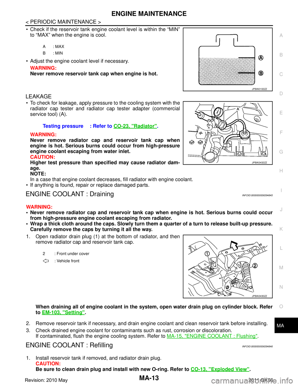
Check if the reservoir tank engine coolant level is within the “MIN”
to “MAX” when the engine is cool.
Adjust the engine coolant level if necessary. WARNING:
Never remove reservoir tank cap when engine is hot.
LEAKAGE
To check for leakage, apply pressure to the cooling system with theradiator cap tester and radiator cap tester adapter (commercial
service tool) (A).
WARNING:
Never remove radiator cap and reservoir tank cap when
engine is hot. Serious burns could occur from high-pressure
engine coolant escaping from water inlet.
CAUTION:
Higher test pressure than specified may cause radiator dam-
age.
NOTE:
In a case that engine coolant decreas es, fill radiator with engine coolant.
If anything is found, repair or replace damaged parts.
ENGINE COOLANT : DrainingINFOID:0000000006394845
WARNING:
Never remove radiator cap and reservoir tank cap when engine is hot. Serious burns could occur
from high-pressure engine co olant escaping from radiator.
Wrap a thick cloth around the caps. Slowly turn them a quarter of a turn to release built-up pressure.
Carefully remove the caps by turning it all the way.
1. Open radiator drain plug (1) at the bottom of radiator, and then remove radiator cap and reservoir tank cap.
When draining all of engine cool ant in the system, open water drai n plug on cylinder block. Refer
to EM-103, "
Setting".
2. Remove reservoir tank if necessary, and drain engine coolant and clean reservoir tank before installing.
3. Check drained engine coolant for contaminants such as rust, corrosion or discoloration. If contaminated, flush the engine cooling system. Refer to MA-15, "
ENGINE COOLANT : Flushing".
ENGINE COOLANT : RefillingINFOID:0000000006394846
1. Install reservoir tank if removed, and radiator drain plug.
CAUTION:
Be sure to clean drain plug and install with new O-ring. Refer to CO-13, "
Exploded View".
A: MAX
B: MIN
JPBIA0102ZZ
Testing pressure : Refer to CO-23, "Radiator".
JPBIA3432ZZ
2 : Front under cover
: Vehicle front
JPBIA3430ZZ
Revision: 2010 May2011 QX56
Page 3684 of 5598
MA-14
< PERIODIC MAINTENANCE >
ENGINE MAINTENANCE
If water drain plug on cylinder block is removed, close and tighten it. Refer to EM-107, "Disassem-
bly and Assembly".
2. Check that each hose clamp is firmly tightened.
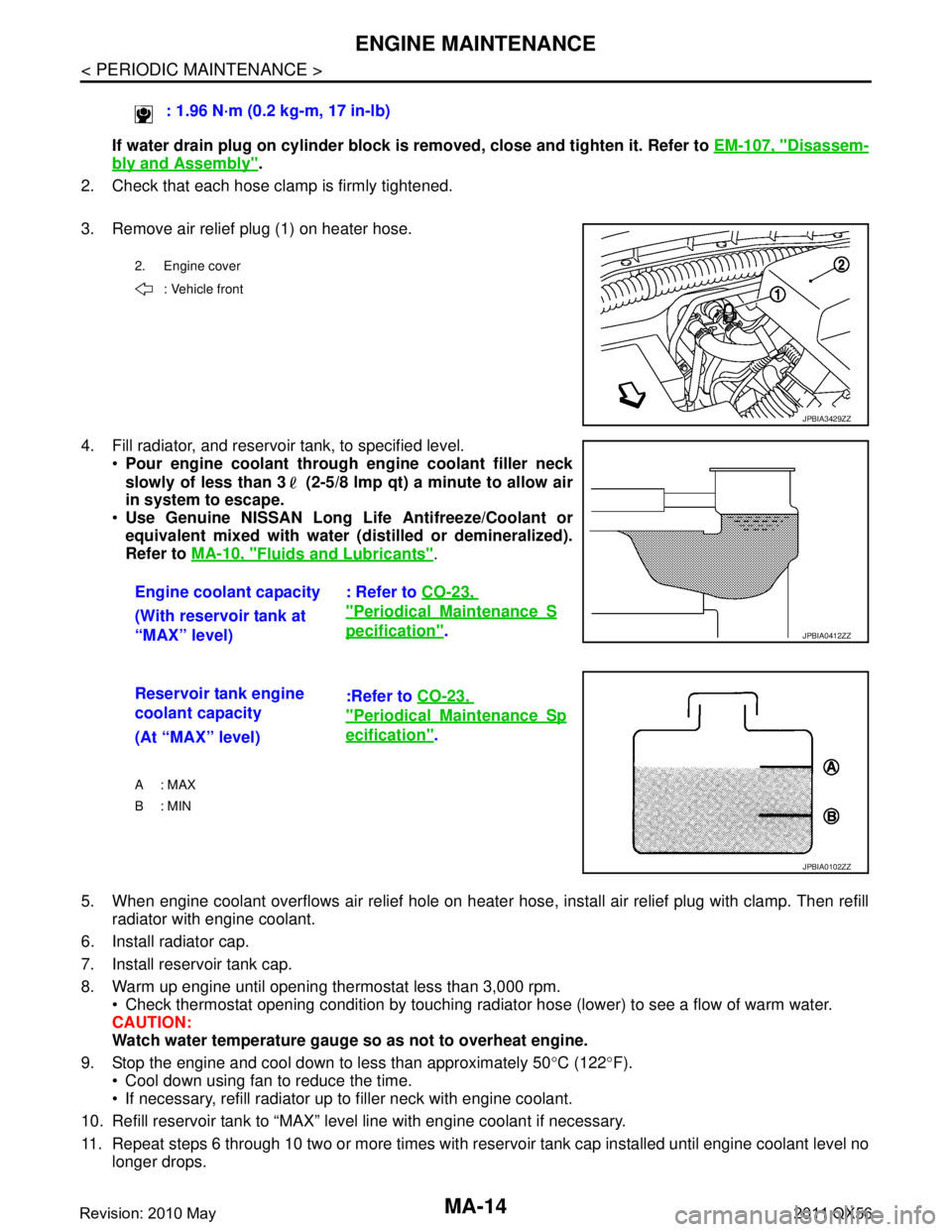
3. Remove air relief plug (1) on heater hose.
4. Fill radiator, and reservoir tank, to specified level. Pour engine coolant through engine coolant filler neck
slowly of less than 3 (2-5/8 lmp qt) a minute to allow air
in system to escape.
Use Genuine NISSAN Long Life Antifreeze/Coolant or
equivalent mixed with water (d istilled or demineralized).
Refer to MA-10, "
Fluids and Lubricants".
5. When engine coolant overflows air relief hole on heater hose, install air relief plug with clamp. Then refill
radiator with engine coolant.
6. Install radiator cap.
7. Install reservoir tank cap.
8. Warm up engine until opening thermostat less than 3,000 rpm. Check thermostat opening condition by touching radiator hose (lower) to see a flow of warm water.
CAUTION:
Watch water temperature gauge so as not to overheat engine.
9. Stop the engine and cool down to less than approximately 50 °C (122 °F).
Cool down using fan to reduce the time.
If necessary, refill radiator up to filler neck with engine coolant.
10. Refill reservoir tank to “MAX” level line with engine coolant if necessary.
11. Repeat steps 6 through 10 two or more times with reservoir tank cap installed until engine coolant level no longer drops. : 1.96 N·m (0.2 kg-m, 17 in-lb)
2. Engine cover
: Vehicle front
JPBIA3429ZZ
Engine coolant capacity : Refer to CO-23,
"PeriodicalMaintenanceS
pecification".
(With reservoir tank at
“MAX” level)JPBIA0412ZZ
Reservoir tank engine
coolant capacity :Refer to
CO-23,
"PeriodicalMaintenanceSp
ecification".
(At “MAX” level)
A : MAX
B: MIN
JPBIA0102ZZ
Revision: 2010 May2011 QX56
Page 3685 of 5598
ENGINE MAINTENANCEMA-15
< PERIODIC MAINTENANCE >
C
DE
F
G H
I
J
K L
M B
MA
N
O A
12. Check cooling system for leakage with engine running.
13. Warm up the engine, and check for sound of engine coolant flow while running engine from idle up to
3,000 rpm with heater temperature controller se t at several position between “COOL” and “WARM”.
Sound may be noticeable at heater unit.
14. Repeat step 13 three times.
15. If sound is heard, bleed air from cooling system by repeating step 4, and steps from 6 to 14 until engine
coolant level no longer drops.
ENGINE COOLANT : FlushingINFOID:0000000006394847
1. Install reservoir tank if removed, and radiator drain plug. CAUTION:
Be sure to clean drain plug and install with new O-ring. Refer to CO-13, "
Exploded View".
If water drain plug on cylinder block is removed, close and tighten it. Refer to EM-107, "
Disassem-
bly and Assembly".
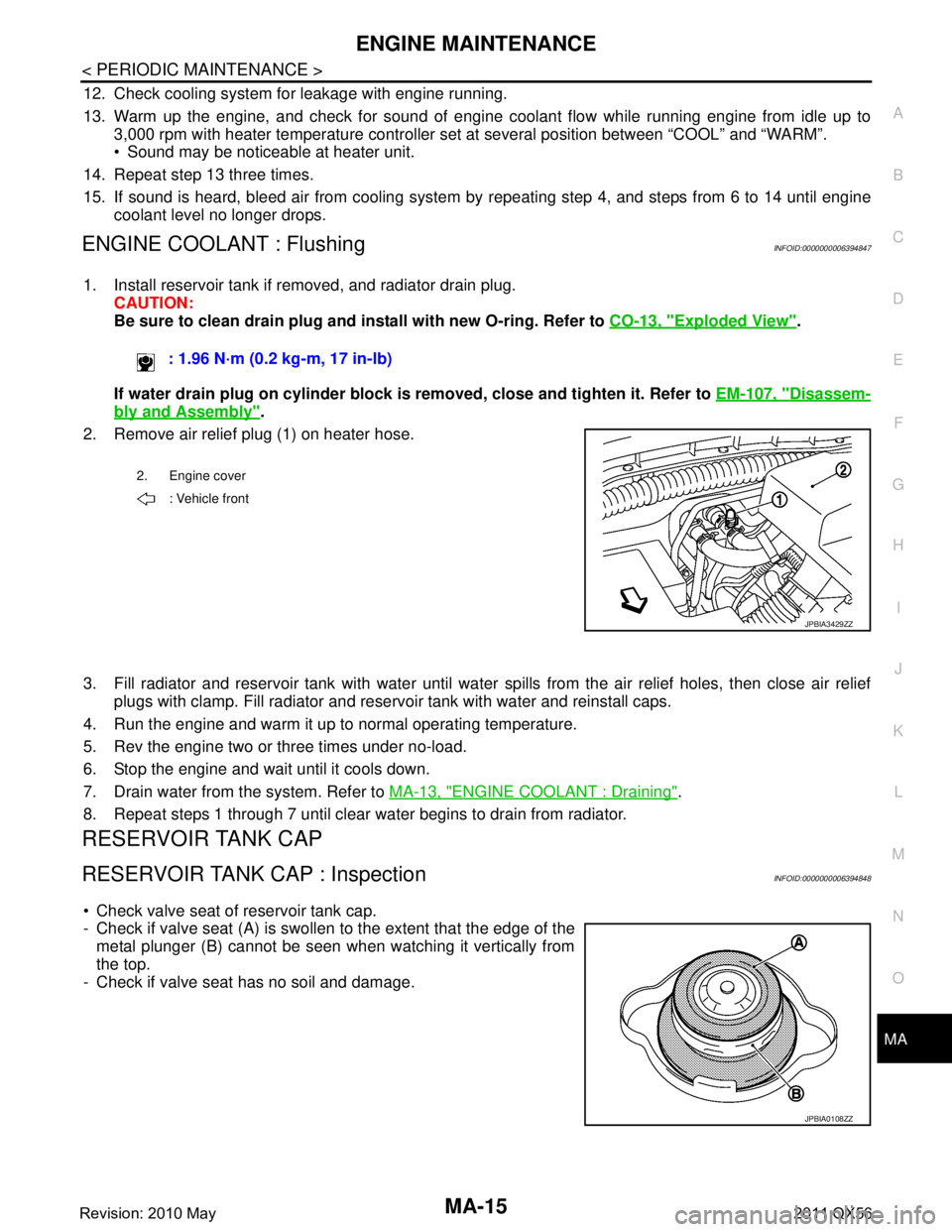
2. Remove air relief plug (1) on heater hose.
3. Fill radiator and reservoir tank with water until water spills from the air relief holes, then close air relief
plugs with clamp. Fill radiator and rese rvoir tank with water and reinstall caps.
4. Run the engine and warm it up to normal operating temperature.
5. Rev the engine two or three times under no-load.
6. Stop the engine and wait until it cools down.
7. Drain water from the system. Refer to MA-13, "
ENGINE COOLANT : Draining".
8. Repeat steps 1 through 7 until clear water begins to drain from radiator.
RESERVOIR TANK CAP
RESERVOIR TANK CAP : InspectionINFOID:0000000006394848
Check valve seat of reservoir tank cap.
- Check if valve seat (A) is swollen to the extent that the edge of the metal plunger (B) cannot be seen when watching it vertically from
the top.
- Check if valve seat has no soil and damage. : 1.96 N·m (0.2 kg-m, 17 in-lb)
2. Engine cover
: Vehicle front
JPBIA3429ZZ
JPBIA0108ZZ
Revision: 2010 May2011 QX56