2011 INFINITI QX56 coolant reservoir
[x] Cancel search: coolant reservoirPage 2426 of 5598
![INFINITI QX56 2011 Factory Service Manual
EC-402
< DTC/CIRCUIT DIAGNOSIS >[VK56VD]
P1217 ENGINE OVER TEMPERATURE
YES >> GO TO 3.
NO >> GO TO 4.
3.CHECK ENGINE COOLANT LEAKAGE-II
Check the following for leakage.
Hose
Radiator
Water pump
INFINITI QX56 2011 Factory Service Manual
EC-402
< DTC/CIRCUIT DIAGNOSIS >[VK56VD]
P1217 ENGINE OVER TEMPERATURE
YES >> GO TO 3.
NO >> GO TO 4.
3.CHECK ENGINE COOLANT LEAKAGE-II
Check the following for leakage.
Hose
Radiator
Water pump](/manual-img/42/57033/w960_57033-2425.png)
EC-402
< DTC/CIRCUIT DIAGNOSIS >[VK56VD]
P1217 ENGINE OVER TEMPERATURE
YES >> GO TO 3.
NO >> GO TO 4.
3.CHECK ENGINE COOLANT LEAKAGE-II
Check the following for leakage.
Hose
Radiator
Water pump
>> Repair or replace malfunctioning part.
4.CHECK RESERVOIR TANK CAP
Check reservoir tank cap. Refer to CO-11, "
RESERVOIR TANK CAP : Inspection".
Is the inspection result normal?
YES >> GO TO 5.
NO >> Replace reservoir tank cap.
5.CHECK THERMOSTAT
Check thermostat. Refer to CO-21, "
Inspection".
Is the inspection result normal?
YES >> GO TO 6.
NO >> Replace thermostat. Refer to CO-20, "
Removal and Installation".
6.CHECK ENGINE COOLANT TEMPERATURE SENSOR
Refer to EC-216, "
Component Inspection (Engine Coolant Temperature Sensor)".
Is the inspection result normal?
YES >> GO TO 7.
NO >> Replace engine coolant temperature sensor. Refer to EM-86, "
Exploded View".
7.CHECK MAIN 12 CAUSES
If the cause cannot be isolated, check the CO-6, "
TroubleshootingChart".
>> INSPECTION END
Revision: 2010 May2011 QX56
Page 2602 of 5598

EM-40
< REMOVAL AND INSTALLATION >
EXHAUST MANIFOLD AND THREE WAY CATALYST
EXHAUST MANIFOLD AND THREE WAY CATALYST
Exploded ViewINFOID:0000000006289550
Removal and InstallationINFOID:0000000006289551
REMOVAL
WARNING:
Perform the work when the exhaust and cooling system have cooled sufficiently.
1. Drain engine coolant from radiator. Refer to CO-8, "
Draining".
CAUTION:
Perform this step when the engine is cold.
Never spill engine coolant on drive belt.
2. Remove reservoir tank. Refer to CO-13, "
Exploded View".
3. Remove drive belt. Refer to EM-20, "
Removal and Installation".
4. Remove power steering oil pump. Refer to ST-48, "
Exploded View".
5. Remove radiator. Refer to CO-13, "
Exploded View".
6. Remove front under cover. Refer to EXT-25, "
Exploded View".
7. Remove front wheels and tires. Refer to WT-64, "
Exploded View".
8. Remove A/C compressor. Refer to HA-30, "
Exploded View".
9. Remove alternator and alternator bracket. Refer to CHG-25, "
Exploded View".
10. Remove exhaust front tube (bank 1 and bank 2). Refer to EX-5, "
Exploded View".
1. Air fuel ratio sensor 1 (bank 2) 2. Exhaust manifold cover (bank 2) 3. Exhaust manifold and three way cat-
alyst (bank 2)
4. Gasket 5. Exhaust manifold and three way cat-
alyst (bank 1)6. Exhaust manifold cover (bank 1)
7. Air fuel ratio sensor 1 (bank 1)
Refer to GI-4, "
Components" for symbols in the figure.
JSBIA0389GB
Revision: 2010 May2011 QX56
Page 2624 of 5598

EM-62
< REMOVAL AND INSTALLATION >
TIMING CHAIN
Removal and Installation
INFOID:0000000006289566
REMOVAL
1. Release fuel pressure. Refer to EC-153, "Work Procedure".
2. Drain engine coolant from radiator. Refer to CO-8, "
Draining".
3. Remove fan shroud (lower). Refer to CO-13, "
Exploded View".
4. Remove fan bracket. Refer to CO-16, "
Exploded View".
5. Remove drive belt auto-tensioner. Refer to EM-26, "
Exploded View".
6. Remove oil level gauge and oil level gauge guide. Refer to EM-57, "
Exploded View".
7. Move power steering oil pump to the posit ion without the hindrance for work. Refer to ST-48, "
Exploded
View".
8. Remove alternator, alternator bracket and alternator stay. Refer to CHG-25, "
Exploded View".
9. Move power steering reservoir tank to the position without the hindrance for work, and then remove Res- ervoir tank bracket. Refer to ST-54, "
Exploded View".
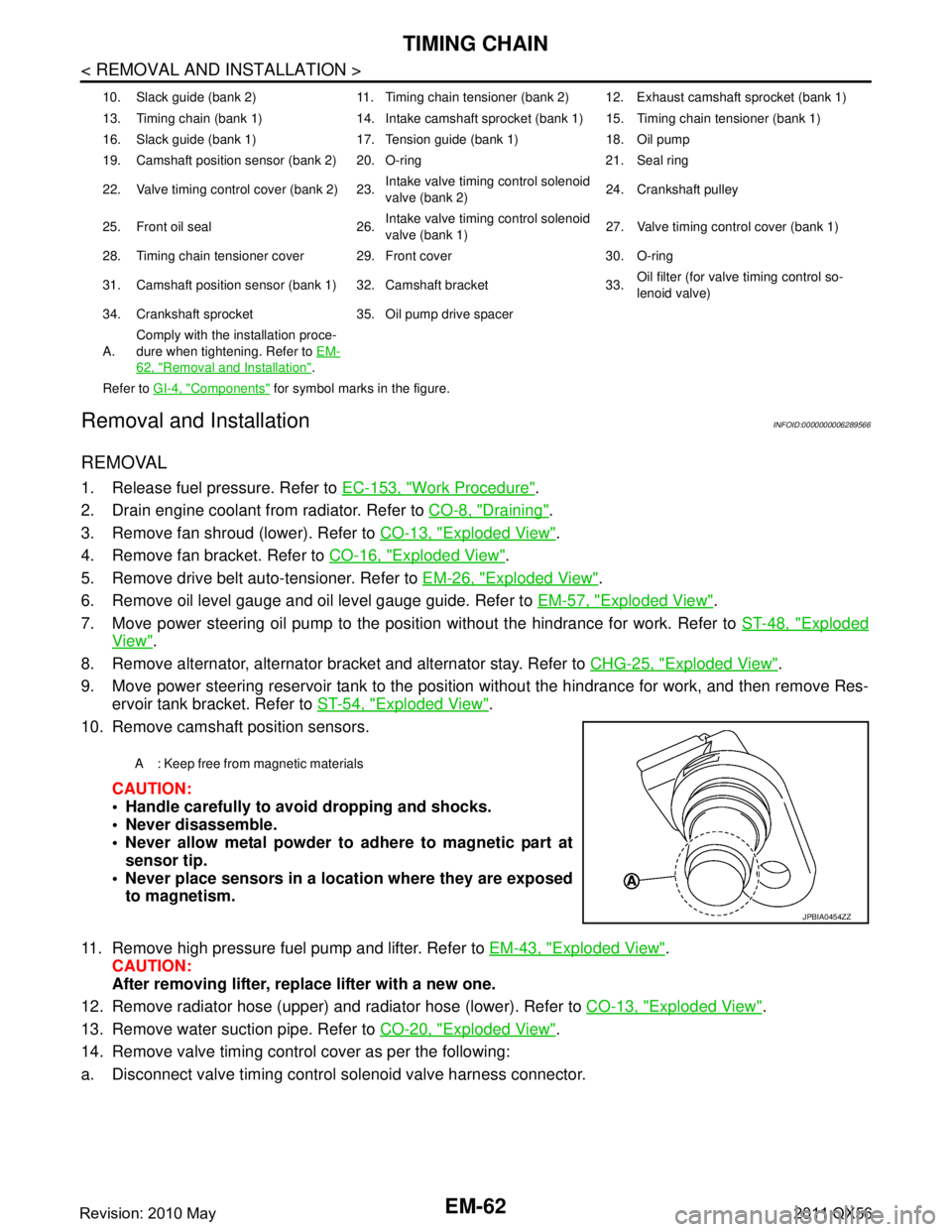
10. Remove camshaft position sensors.
CAUTION:
Handle carefully to avoid dropping and shocks.
Never disassemble.
Never allow metal powder to adhere to magnetic part atsensor tip.
Never place sensors in a lo cation where they are exposed
to magnetism.
11. Remove high pressure fuel pump and lifter. Refer to EM-43, "
Exploded View".
CAUTION:
After removing lifter, replace lifter with a new one.
12. Remove radiator hose (upper) and radiator hose (lower). Refer to CO-13, "
Exploded View".
13. Remove water suction pipe. Refer to CO-20, "
Exploded View".
14. Remove valve timing control cover as per the following:
a. Disconnect valve timing control solenoid valve harness connector.
10. Slack guide (bank 2) 11. Timing chain tensioner (bank 2) 12. Exhaust camshaft sprocket (bank 1)
13. Timing chain (bank 1) 14. Intake camshaft sprocket (bank 1) 15. Timing chain tensioner (bank 1)
16. Slack guide (bank 1) 17. Tension guide (bank 1) 18. Oil pump
19. Camshaft position sensor (bank 2) 20. O-ring 21. Seal ring
22. Valve timing control cover (bank 2) 23. Intake valve timing control solenoid
valve (bank 2)24. Crankshaft pulley
25. Front oil seal 26. Intake valve timing control solenoid
valve (bank 1)27. Valve timing control cover (bank 1)
28. Timing chain tensioner cover 29. Front cover 30. O-ring
31. Camshaft position sensor (bank 1) 32. Camshaft bracket 33. Oil filter (for valve timing control so-
lenoid valve)
34. Crankshaft sprocket 35. Oil pump drive spacer
A. Comply with the installation proce-
dure when tightening. Refer to
EM-
62, "Removal and Installation".
Refer to GI-4, "
Components" for symbol marks in the figure.
A : Keep free from magnetic materials
JPBIA0454ZZ
Revision: 2010 May2011 QX56
Page 2661 of 5598

ENGINE ASSEMBLYEM-99
< UNIT REMOVAL AND INSTALLATION >
C
DE
F
G H
I
J
K L
M A
EM
NP
O
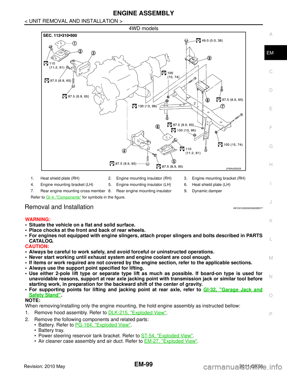
4WD models
Removal and InstallationINFOID:0000000006289577
WARNING:
Situate the vehicle on a flat and solid surface.
Place chocks at the front
and back of rear wheels.
For engines not equipped with engi ne slingers, attach proper slingers and bolts described in PARTS
CATALOG.
CAUTION:
Always be careful to work safely, and avo id forceful or uninstructed operations.
Never start working until exhaust system and engine coolant are cool enough.
If items or work required are not covered by th e engine section, refer to the applicable sections.
Always use the support poin t specified for lifting.
Use either 2-pole lift type or separate type lift as much as possible. If board-on type is used for
unavoidable reasons, support at r ear axle jacking point with transmi ssion jack or similar tool before
starting work, in preparat ion for the backward shift of the center of gravity.
For supporting points fo r lifting and jacking point at rear axle, refer to GI-32, "
Garage Jack and
Safety Stand".
NOTE:
When removing/installing only the engine mounting, the hold engine assembly as instructed bellow:
1. Remove hood assembly. Refer to DLK-215, "
Exploded View".
2. Remove the following components and related parts: Battery. Refer to PG-164, "
Exploded View".
Battery tray.
Power steering reservoir tank bracket. Refer to ST-54, "
Exploded View".
Air cleaner case assembly and air duct. Refer to EM-27, "
Exploded View".
JPBIA4256GB
1. Heat shield plate (RH) 2. Engine mounting insulator (RH) 3. Engine mounting bracket (RH)
4. Engine mounting bracket (LH) 5. Engine mounting insulator (LH) 6. Heat shield plate (LH)
7. Rear engine mounting cross member 8. Rear engine mounting insulator 9. Dynamic damper
Refer to GI-4, "
Components" for symbols in the figure.
Revision: 2010 May2011 QX56
Page 2663 of 5598

ENGINE ASSEMBLYEM-101
< UNIT REMOVAL AND INSTALLATION >
C
DE
F
G H
I
J
K L
M A
EM
NP
O
5. Remove A/T assembly. Refer to
TM-205, "2WD : Exploded View" (2WD models) or TM-208, "4WD :
Exploded View" (4WD models).
6. Remove steering gear assembly. Refer to ST-41, "
Exploded View".
7. Remove front final drive assembly. Refer to DLN-162, "
Exploded View".
8. Remove exhaust manifold. Refer to EM-40, "
Exploded View".
9. Remove alternator. Refer to CHG-25, "
Exploded View".
Engine Room LH
1. Remove air cleaner and air duct. Refer to EM-27, "Exploded View".
2. Remove A/C compressor. Refer to HA-30, "
Exploded View".
3. Disconnect fuel feed hose and EVAP hose. Refer to EM-43, "
Exploded View".
CAUTION:
Fit plugs onto disconnected hoses to prevent fuel leakage.
Engine Room RH
1. Remove power steering oil pump and reservoir tank. Refer to ST-48, "Exploded View".
2. Disconnect heater hose at heater core side, and fit a plug onto hose end to prevent engine coolant leak-
age.
3. Disconnect ground cable.
4. Disconnect all clips and connectors of the engine harness from vehicle side.
Removal Work
1. Install alternator bracket. Refer to CHG-25, "Exploded View".
Temporarily tighten mounting bolts.
2. Remove intake manifold. Refer to EM-30, "
Exploded View".
3. Remove starter motor. Refer to STR-17, "
Exploded View".
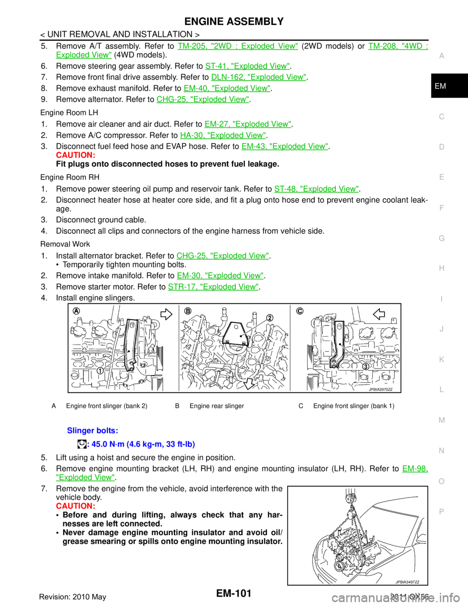
4. Install engine slingers.
5. Lift using a hoist and secure the engine in position.
6. Remove engine mounting bracket (LH, RH) and engine mounting insulator (LH, RH). Refer to EM-98,
"Exploded View".
7. Remove the engine from the vehi cle, avoid interference with the
vehicle body.
CAUTION:
Before and during lifting, always check that any har-
nesses are left connected.
Never damage engine mounti ng insulator and avoid oil/
grease smearing or spills onto engine mounting insulator.
A Engine front slinger (bank 2) B Engine rear slinger C Engine front slinger (bank 1)
Slinger bolts:
: 45.0 N·m (4.6 kg-m, 33 ft-lb)
JPBIA3970ZZ
JPBIA3497ZZ
Revision: 2010 May2011 QX56
Page 3246 of 5598
![INFINITI QX56 2011 Factory Service Manual
HAC-140
< SYMPTOM DIAGNOSIS >[AUTOMATIC AIR CONDITIONING]
INSUFFICIENT HEATING
INSUFFICIENT HEATING
FRONT AIR CONDITIONER
FRONT AIR CONDITIONER : DescriptionINFOID:0000000006275990
Symptom Insuffici INFINITI QX56 2011 Factory Service Manual
HAC-140
< SYMPTOM DIAGNOSIS >[AUTOMATIC AIR CONDITIONING]
INSUFFICIENT HEATING
INSUFFICIENT HEATING
FRONT AIR CONDITIONER
FRONT AIR CONDITIONER : DescriptionINFOID:0000000006275990
Symptom Insuffici](/manual-img/42/57033/w960_57033-3245.png)
HAC-140
< SYMPTOM DIAGNOSIS >[AUTOMATIC AIR CONDITIONING]
INSUFFICIENT HEATING
INSUFFICIENT HEATING
FRONT AIR CONDITIONER
FRONT AIR CONDITIONER : DescriptionINFOID:0000000006275990
Symptom Insufficient heating
No warm air comes out. (Air flow volume is normal.)
FRONT AIR CONDITIONER
: Diagnosis ProcedureINFOID:0000000006275991
NOTE:
Perform self-diagnoses with on board diagnosis and CO NSULT-III before performing symptom diagnosis. If
DTC is detected, perform the corresponding diagnosis.
1.CHECK COOLING SYSTEM
1. Check engine coolant level and check leakage. Refer to CO-8, "
Inspection".
2. Check reservoir tank cap. Refer to CO-11, "
RESERVOIR TANK CAP : Inspection".
3. Check water flow sounds of the engine coolant. Refer to CO-9, "
Refilling".
Is the inspection result normal?
YES >> GO TO 2.
NO >> Refill engine coolant and repair or repl ace parts depending on the inspection results.
2.CHECK HEATER HOSE
Check installation of heater hose by visually or touching.
Is the inspection result normal?
YES >> GO TO 3.
NO >> Repair or replace parts depending on the inspection results.
3.CHECK FRONT HEATER CORE
1. Check temperature of inlet hose and outlet hose of front heater core.
2. Check that inlet side of front heater core is hot and t he outlet side is slightly lower than/almost equal to the
inlet side.
CAUTION:
Always perform the temperature in spection in a short period of time because the engine coolant
temperature is very hot.
Is the inspection result normal?
YES >> GO TO 4.
NO >> Replace front heater core. Refer to HA-44, "
HEATER CORE : Removal and Installation".
4.CHECK AIR LEAKAGE FROM EACH DUCT
Check duct and nozzle, etc. of front air conditioning system for air leakage.
Is the inspection result normal?
YES >> GO TO 5.
NO >> Repair or replace parts depending on the inspection results.
5.CHECK SETTING OF TEMPERATURE SETTING TRIMMER (FRONT)
1. Check setting value of temperature setting trimmer (front). Refer to HAC-68, "
FRONT AUTOMATIC AIR
CONDITIONING SYSTEM : Temperature Setting Trimmer (Front)".
2. Check that temperature setting trimmer (front) is set to “ − direction”.
NOTE:
The control temperature can be set by t he temperature setting trimmer (front).
3. Set difference between the set temperature and control temperature to “0”.
Are the symptoms solved?
YES >> INSPECTION END
NO >> Replace A/C auto amp.. Refer to HAC-146, "
Removal and Installation".
REAR AIR CONDITIONER
Revision: 2010 May2011 QX56
Page 3247 of 5598
![INFINITI QX56 2011 Factory Service Manual
INSUFFICIENT HEATINGHAC-141
< SYMPTOM DIAGNOSIS > [AUTOMATIC AIR CONDITIONING]
C
D
E
F
G H
J
K L
M A
B
HAC
N
O P
REAR AIR CONDITIONER : DescriptionINFOID:0000000006275992
Symptom
Insufficient heati INFINITI QX56 2011 Factory Service Manual
INSUFFICIENT HEATINGHAC-141
< SYMPTOM DIAGNOSIS > [AUTOMATIC AIR CONDITIONING]
C
D
E
F
G H
J
K L
M A
B
HAC
N
O P
REAR AIR CONDITIONER : DescriptionINFOID:0000000006275992
Symptom
Insufficient heati](/manual-img/42/57033/w960_57033-3246.png)
INSUFFICIENT HEATINGHAC-141
< SYMPTOM DIAGNOSIS > [AUTOMATIC AIR CONDITIONING]
C
D
E
F
G H
J
K L
M A
B
HAC
N
O P
REAR AIR CONDITIONER : DescriptionINFOID:0000000006275992
Symptom
Insufficient heating
No warm air comes out. (Air flow volume is normal.)
REAR AIR CONDITIONER : Diagnosis ProcedureINFOID:0000000006275993
CAUTION:
Perform the self-diagnoses with on board diagnosi s and CONSULT-III before performing symptom
diagnosis. If any malfunction result or DTC is detected, perform the corresponding diagnosis.
1.CHECK COOLING SYSTEM
1. Check engine coolant level and check leakage. Refer to CO-8, "
Inspection".
2. Check reservoir tank cap. Refer to CO-11, "
RESERVOIR TANK CAP : Inspection".
3. Check water flow sounds of the engine coolant. Refer to CO-9, "
Refilling".
Is the inspection result normal?
YES >> GO TO 2.
NO >> Refill the engine coolant and repair or replace the parts depending on the inspection results.
2.CHECK HEATER HOSE
Check installation of heater hose by visually or touching.
Is the inspection result normal?
YES >> GO TO 3.
NO >> Repair or replace parts depending on the inspection results.
3.CHECK REAR HEATER CORE
1. Check temperature of inlet hose and outlet hose of rear heater core.
2. Check that the inlet side of rear heater core is hot and the outlet side is slightly lower than/almost equal to
the inlet side.
CAUTION:
Always perform the temperature inspection in a sh ort period of time because the engine coolant
temperature is very hot.
Is the inspection result normal?
YES >> GO TO 4.
NO >> Replace rear heater core. Refer to HA-48, "
HEATER CORE : Removal and Installation".
4.CHECK AIR LEAKAGE FROM EACH DUCT
Check duct and nozzle, etc. of the rear air conditioning system for air leakage.
Is the inspection result normal?
YES >> GO TO 5.
NO >> Repair or replace parts depending on the inspection results.
5.CHECK SETTING OF TEMPERATURE SETTING TRIMMER (REAR)
1. Check setting value of temperature setting trimmer (rear). Refer to HAC-69, "
REAR AUTOMATIC AIR
CONDITIONING SYSTEM : Temperature Setting Trimmer (Rear)".
2. Check that the temperature setting trimmer is set to “ − direction”.
NOTE:
The control temperature can be set by the temperature setting trimmer (rear).
3. Set the difference between the set temperature (rear) and control temperature to “0”.
Are the symptoms solved?
YES >> INSPECTION END
NO >> Replace A/C auto amp.. Refer to HAC-146, "
Removal and Installation".
Revision: 2010 May2011 QX56
Page 3671 of 5598

MA-1
MAINTENANCE
C
DE
F
G H
I
J
K L
M B
MA
SECTION MA
N
O A
CONTENTS
MAINTENANCE
PREPARATION .............
...............................3
PREPARATION .............................................. .....3
Special Service Tool ........................................... ......3
Commercial Service Tool ..........................................3
PERIODIC MAINTENANCE ..........................4
GENERAL MAINTENANCE ........................... .....4
Explanation of General Maintenance .................. ......4
PERIODIC MAINTENANCE ................................6
Introduction of Periodic Maintenance .................. ......6
Schedule 1 ................................................................6
Schedule 2 ................................................................8
RECOMMENDED FLUIDS AND LUBRI-
CANTS ................................................................
10
Fluids and Lubricants .......................................... ....10
Engine Oil Recommendation ..................................10
Anti-Freeze Coolant Mixture Ratio ..........................11
ENGINE MAINTENANCE ...................................12
DRIVE BELTS ....................................................... ....12
DRIVE BELTS : Exploded View ..............................12
DRIVE BELTS : Checking .......................................12
DRIVE BELTS : Tension Adjustment .....................12
ENGINE COOLANT ............................................... ....12
ENGINE COOLANT : Inspection .............................12
ENGINE COOLANT : Draining ................................13
ENGINE COOLANT : Refilling ................................13
ENGINE COOLANT : Flushing ...............................15
RESERVOIR TANK CAP ..........................................15
RESERVOIR TANK CAP : Inspection ................. ....15
RADIATOR ............................................................ ....16
RADIATOR : Inspection ..........................................16
FUEL LINES .......................................................... ....16
FUEL LINES : Inspection ........................................17
AIR CLEANER FILTER ......................................... ....17
AIR CLEANER FILTER : Removal and Installation
....
17
ENGINE OIL ........................................................... ....17
ENGINE OIL : Draining ............................................17
ENGINE OIL : Refilling ............................................17
OIL FILTER ............................................................ ....18
OIL FILTER : Removal and Installation ...................18
SPARK PLUG ........................................................ ....18
SPARK PLUG : Removal and Installation ...............19
SPARK PLUG : Inspection ......................................19
EVAP VAPOR LINES ............................................ ....20
EVAP VAPOR LINES : Inspection ...........................20
CHASSIS MAINTENANCE ...............................21
EXHAUST SYSTEM . ..................................................21
EXHAUST SYSTEM : Inspec tion ............................21
A/T FLUID .............................................................. ....21
A/T FLUID : Inspection ............................................21
TRANSFER FLUID ................................................ ....21
TRANSFER FLUID : Inspection ..............................21
TRANSFER FLUID : Draining .................................21
TRANSFER FLUID : Refilling ..................................22
FRONT PROPELLER SHAFT: 2F P15 ................. ....22
FRONT PROPELLER SHAFT: 2F P15 : Inspec-
tion ...........................................................................
22
REAR PROPELLER SHAFT: 2F P26 .................... ....23
REAR PROPELLER SHAFT: 2F P26 : Inspection ....23
REAR PROPELLER SHAFT: 2S1410 ................... ....23
REAR PROPELLER SHAFT: 2S1410 : Inspection ....23
FRONT DIFFERENTIAL GEAR OIL: R180A ........ ....24
FRONT DIFFERENTIAL GEAR OIL: R180A : In-
spection ...................................................................
24
Revision: 2010 May2011 QX56