Page 1636 of 5598

DLK-100
< DTC/CIRCUIT DIAGNOSIS >
B2424 CLOSURE CONDITION
B2424 CLOSURE CONDITION
DTC LogicINFOID:0000000006225903
DTC DETECTION LOGIC
DTC CONFIRMATION PROCEDURE
1.PERFORM DTC CONFIRMATION PROCEDURE
1. Turn ignition switch ON.
2. Check “Self Diagnostic Result” mode of “AUTOMAT IC BACK DOOR CONTROL UNIT” using CONSULT-
III.
Is DTC detected?
YES >> Refer to DLK-100, "Diagnosis Procedure".
NO >> INSPECTION END
Diagnosis ProcedureINFOID:0000000006225904
1.CHECK OPEN/CLOSE SWITCH SIGNAL
1. Select “AUTOMATIC BACK DOOR CONTROL UNIT” using CONSULT-III.
2. Select “CLOSE SW”, “OPEN SW” in “DATA MONITOR” mode.
3. Check that the function operates normall y according to the following conditions.
Is the inspection result normal?
YES >> GO TO 6.
NO >> GO TO 2.
2.CHECK AUTOMATIC BACK DOOR CONTROL MODULE OUTPUT
1. Turn ignition switch OFF.
2. Disconnect back door lock assembly connector.
3. Check voltage between back door lock assembly harness connector and ground.
Is the inspection result normal?
YES >> GO TO 4.
NO >> GO TO 3.
3.CHECK OPEN/CLOSE SWITCH CIRCUIT
1. Disconnect automatic back door control module connector.
DTC CONSULT-III display de-
scription DTC detecting condition Possible cause
B2424 CLSR CONDITION When the following conditions are detected after
OPEN/CLOSE operation of the back door closure
motor
Open switch and close switch are ON Harness or connector
(Open switch or close switch
circuit is open or shorted)
Back door lock assembly
Monitor item Condition Status
OPEN SW Back doorHalf latch/fully closed OFF
Open ON
CLOSE SW Open/half latch OFF
Fully closed ON
(+)
(–)Vo l ta g e
(Approx.)
Back door lock assembly
Connector Terminal
D157 4
Ground Battery voltage
5
Revision: 2010 May2011 QX56
Page 1637 of 5598
B2424 CLOSURE CONDITIONDLK-101
< DTC/CIRCUIT DIAGNOSIS >
C
DE
F
G H
I
J
L
M A
B
DLK
N
O P
2. Check continuity between automatic back door control module harness connector and back door lock
assembly harness connector.
3. Check continuity between automatic back door control module harness connector and ground.
Is the inspection result normal?
YES >> Replace automatic back door control module. Refer to DLK-262, "Removal and Installation".
NO >> Repair or replace harness.
4.CHECK GROUND CIRCUIT
Check continuity between back door lo ck assembly harness connector and ground.
Is the inspection result normal?
YES >> GO TO 5.
NO >> Repair or replace harness.
5.CHECK OPEN/CLOSE SWITCH
Refer to DLK-101, "
Component Inspection".
Is the inspection result normal?
YES >> GO TO 6.
NO >> Replace back door lock assembly.
6.CHECK INTERMITTENT INCIDENT
Refer to GI-40, "
Intermittent Incident".
>> INSPECTION END
Component InspectionINFOID:0000000006225905
COMPONENT INSPECTION
1.CHECK OPEN/CLOSE SWITCH
1. Turn ignition switch OFF.
2. Disconnect back door lock assembly.
3. Check continuity between back door lock assembly terminals.
Automatic back door control module Back door lock assembly Continuity
Connector Terminal Connector Terminal
B26 19
D157 5
Existed
20 4
Automatic back door control module GroundContinuity
Connector Terminal
B26 19
Not existed
20
Back door lock assembly
GroundContinuity
Connector Terminal
D157 8 Existed
Back door lock assembly Condition Continuity
Te r m i n a l
5 8 Back door lock Fully closed Existed
Open/half latch Not existed
4 Open Existed
Fully closed/half latch Not existed
Revision: 2010 May2011 QX56
Page 1638 of 5598
DLK-102
< DTC/CIRCUIT DIAGNOSIS >
B2424 CLOSURE CONDITION
Is the inspection result normal?
YES >> INSPECTION END
NO >> Replace back door lock assembly.
Revision: 2010 May2011 QX56
Page 1653 of 5598
DOOR SWITCHDLK-117
< DTC/CIRCUIT DIAGNOSIS >
C
DE
F
G H
I
J
L
M A
B
DLK
N
O P
DOOR SWITCH
Component Function CheckINFOID:0000000006225921
1.CHECK FUNCTION
1. Select “DOOR LOCK” of “BCM” using CONSULT-III.
2. Select “DOOR SW-DR”, “DOOR SW-AS”, “DOOR SW-RL”, “DOOR SW-RR”, in “DATA MONITOR” mode.
3. Check that the function operates normall y according to the following conditions.
Is the inspection result normal?
YES >> Door switch is OK.
NO >> Refer to DLK-117, "
Diagnosis Procedure".
Diagnosis ProcedureINFOID:0000000006225922
1.CHECK DOOR SWITCH INPUT SIGNAL
1. Turn ignition switch OFF.
2. Disconnect malfunctioning door switch connector.
3. Check signal between malfunctioning door switch harness connector and ground using oscilloscope.
Monitor item Condition Status
DOOR SW-DR Dri ver side doorOpen On
Closed Off
DOOR SW-AS Passenger side door Open On
Closed Off
DOOR SW-RL Rear door LH Open On
Closed Off
DOOR SW-RR Rear door RH Open On
Closed Off
Revision: 2010 May2011 QX56
Page 1656 of 5598
DLK-120
< DTC/CIRCUIT DIAGNOSIS >
BACK DOOR SWITCH
BACK DOOR SWITCH
Component Function CheckINFOID:0000000006225924
1.CHECK FUNCTION
1. Select “DOOR LOCK” of “BCM” using CONSULT-III.
2. Select “DOOR SW-BK” in “DATA MONITOR” mode.
3. Check that the function operates normall y according to the following conditions.
Is the inspection result normal?
YES >> Door switch is OK.
NO >> Refer to DLK-120, "
Diagnosis Procedure".
Diagnosis ProcedureINFOID:0000000006225925
1.CHECK BACK DOOR SWITCH INPUT SIGNAL
1. Turn ignition switch OFF.
2. Disconnect back door lock assembly connector.
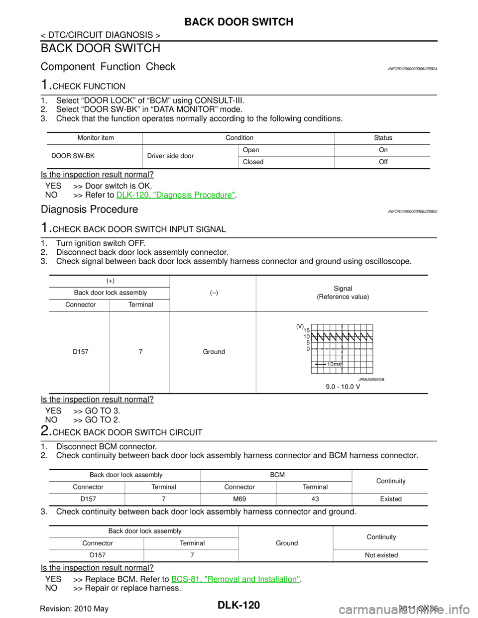
3. Check signal between back door lock assembly harness connector and ground using oscilloscope.
Is the inspection result normal?
YES >> GO TO 3.
NO >> GO TO 2.
2.CHECK BACK DOOR SWITCH CIRCUIT
1. Disconnect BCM connector.
2. Check continuity between back door lock as sembly harness connector and BCM harness connector.
3. Check continuity between back door lock assembly harness connector and ground.
Is the inspection result normal?
YES >> Replace BCM. Refer to BCS-81, "Removal and Installation".
NO >> Repair or replace harness.
Monitor item Condition Status
DOOR SW-BK Driver side door Open On
Closed Off
(+)
(–) Signal
(Reference value)
Back door lock assembly
Connector Terminal
D157 7 Ground 9.0 - 10.0 V
JPMIA0593GB
Back door lock assembly BCM Continuity
Connector Terminal Connector Terminal
D157 7 M69 43 Existed
Back door lock assembly GroundContinuity
Connector Terminal
D157 7 Not existed
Revision: 2010 May2011 QX56
Page 1657 of 5598
BACK DOOR SWITCHDLK-121
< DTC/CIRCUIT DIAGNOSIS >
C
DE
F
G H
I
J
L
M A
B
DLK
N
O P
3.CHECK BACK DOOR SWITCH GROUND CIRCUIT
Check continuity between back door lo ck assembly harness connector and ground.
Is the inspection result normal?
YES >> GO TO 4.
NO >> Repair or replace harness.
4.CHECK BACK DOOR SWITCH
Refer to DLK-121, "
Component Inspection".
Is the inspection result normal?
YES >> GO TO 5.
NO >> Replace back door lock assembly.
5.CHECK INTERMITTENT INCIDENT
Refer to GI-40, "
Intermittent Incident".
>> INSPECTION END
Component InspectionINFOID:0000000006225926
1.CHECK BACK DOOR SWITCH
1. Turn ignition switch OFF.
2. Disconnect back door lock assembly connector.
3. Check continuity between back door lock assembly terminals.
Is the inspection result normal?
YES >> INSPECTION END
NO >> Replace back door lock assembly.
Back door lock assembly
GroundContinuity
Connector Terminal
D157 8 Existed
Back door lock assembly Condition Continuity
Terminal
7 8 Door switch Pressed Not existed
Released Existed
Revision: 2010 May2011 QX56
Page 1658 of 5598

DLK-122
< DTC/CIRCUIT DIAGNOSIS >
DOOR LOCK AND UNLOCK SWITCH
DOOR LOCK AND UNLOCK SWITCH
DRIVER SIDE
DRIVER SIDE : Component Function CheckINFOID:0000000006225927
1.CHECK FUNCTION
1. Select “DOOR LOCK” of “BCM” using CONSULT-III.
2. Select “CDL LOCK SW”, “CDL UNLOCK SW” in “DATA MONITOR” mode.
3. Check that the function operates normall y according to the following conditions.
Is the inspection result normal?
YES >> Door lock and unlock switch is OK.
NO >> Refer to DLK-122, "
DRIVER SIDE : Diagnosis Procedure".
DRIVER SIDE : Diagnosis ProcedureINFOID:0000000006225928
1.CHECK POWER WINDOW SWITCH
1. Turn ignition switch ON.
2. Check power window operation.
Does power window operate?
YES >> Replace power window main switch.
NO >> Refer to PWC-61, "
Diagnosis Procedure".
PASSENGER SIDE
PASSENGER SIDE : Component Function CheckINFOID:0000000006225929
1.CHECK FUNCTION
1. Select “DOOR LOCK” of “BCM” using CONSULT-III.
2. Select “CDL LOCK SW”, “CDL UNLOCK SW” in “DATA MONITOR” mode.
3. Check that the function operates normall y according to the following conditions.
Is the inspection result normal?
YES >> Door lock and unlock switch is OK.
NO >> Refer to DLK-122, "
PASSENGER SIDE : Diagnosis Procedure".
PASSENGER SIDE : Diagnosis ProcedureINFOID:0000000006225930
1.CHECK POWER WINDOW SWITCH
1. Turn ignition switch ON.
2. Check power window operation.
Does power window operate?
YES >> Replace front power window switch (passenger side).
NO >> Refer to PWC-61, "
Diagnosis Procedure".
Monitor item Condition Status
CDL LOCK SW Door lock and unlock switchLock ON
Unlock OFF
CDL UNLOCK SW Lock OFF
Unlock ON
Monitor item Condition Status
CDL LOCK SW Door lock and unlock switchLock ON
Unlock OFF
CDL UNLOCK SW Lock OFF
Unlock ON
Revision: 2010 May2011 QX56
Page 1659 of 5598
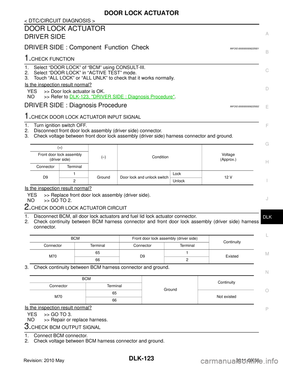
DOOR LOCK ACTUATORDLK-123
< DTC/CIRCUIT DIAGNOSIS >
C
DE
F
G H
I
J
L
M A
B
DLK
N
O P
DOOR LOCK ACTUATOR
DRIVER SIDE
DRIVER SIDE : Comp onent Function CheckINFOID:0000000006225931
1.CHECK FUNCTION
1. Select “DOOR LOCK” of “BCM” using CONSULT-III.
2. Select “DOOR LOCK” in “ACTIVE TEST” mode.
3. Touch “ALL LOCK” or “ALL UNLK” to check that it works normally.
Is the inspection result normal?
YES >> Door lock actuator is OK.
NO >> Refer to DLK-123, "
DRIVER SIDE : Diagnosis Procedure".
DRIVER SIDE : Diag nosis ProcedureINFOID:0000000006225932
1.CHECK DOOR LOCK ACTUATOR INPUT SIGNAL
1. Turn ignition switch OFF.
2. Disconnect front door lock assembly (driver side) connector.
3. Check voltage between front door lock assembly (driver side) harness connector and ground.
Is the inspection result normal?
YES >> Replace front door lock assembly (driver side).
NO >> GO TO 2.
2.CHECK DOOR LOCK ACTUATOR CIRCUIT
1. Disconnect BCM, all door lock actuator s and fuel lid lock actuator connector.
2. Check continuity between BCM harness connector and front door lock assembly (driver side) harness
connector.
3. Check continuity between BCM harness connector and ground.
Is the inspection result normal?
YES >> GO TO 3.
NO >> Repair or replace harness.
3.CHECK BCM OUTPUT SIGNAL
1. Connect BCM connector.
2. Check voltage between BCM harness connector and ground.
(+)
(–) Condition Vo l ta g e
(Approx.)
Front door lock assembly
(driver side)
Connector Terminal
D9 1
Ground Door lock and unlock switch Lock
12 V
2 Unlock
BCM Front door lock assembly (driver side) Continuity
Connector Terminal Connector Terminal
M70 65
D9 1
Existed
66 2
BCM GroundContinuity
Connector Terminal
M70 65
Not existed
66
Revision: 2010 May2011 QX56