2011 INFINITI QX56 ignition
[x] Cancel search: ignitionPage 5493 of 5598
C1750, C1751, C1752, C1753 RECEIVER
WT-43
< DTC/CIRCUIT DIAGNOSIS >
C
D F
G H
I
J
K L
M A
B
WT
N
O P
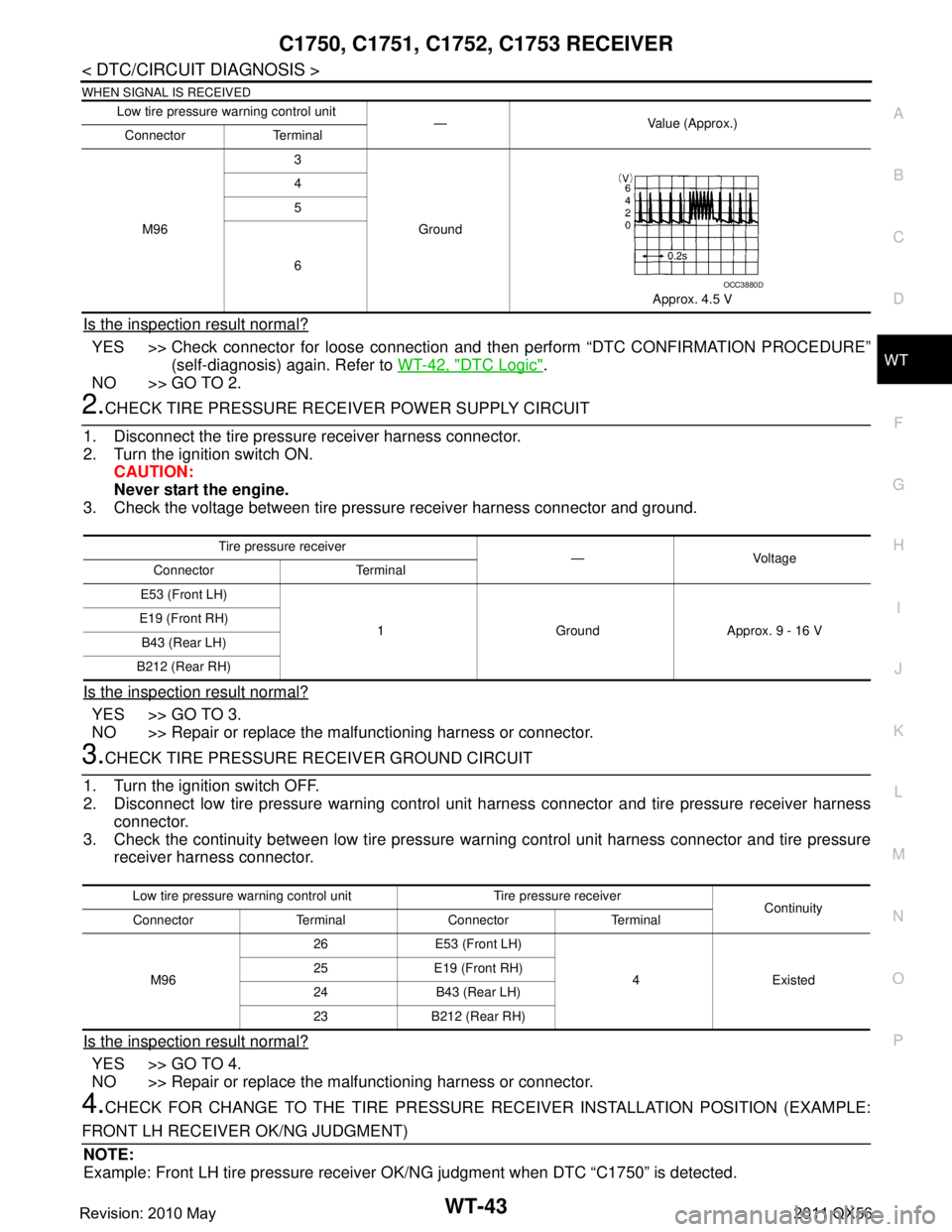
WHEN SIGNAL IS RECEIVED
Is the inspection result normal?
YES >> Check connector for loose connection and t hen perform “DTC CONFIRMATION PROCEDURE”
(self-diagnosis) again. Refer to WT-42, "
DTC Logic".
NO >> GO TO 2.
2.CHECK TIRE PRESSURE RECE IVER POWER SUPPLY CIRCUIT
1. Disconnect the tire pressure receiver harness connector.
2. Turn the ignition switch ON. CAUTION:
Never start the engine.
3. Check the voltage between tire pressure receiver harness connector and ground.
Is the inspection result normal?
YES >> GO TO 3.
NO >> Repair or replace the malfunctioning harness or connector.
3.CHECK TIRE PRESSURE RECEIVER GROUND CIRCUIT
1. Turn the ignition switch OFF.
2. Disconnect low tire pressure warning control unit harness connector and tire pressure receiver harness connector.
3. Check the continuity between low tire pressure warning control unit harness connector and tire pressure
receiver harness connector.
Is the inspection result normal?
YES >> GO TO 4.
NO >> Repair or replace the malfunctioning harness or connector.
4.CHECK FOR CHANGE TO THE TIRE PRESSURE RECEIVER INSTALLATION POSITION (EXAMPLE:
FRONT LH RECEIVER OK/NG JUDGMENT) NOTE:
Example: Front LH tire pressure receiver OK/NG judgment when DTC “C1750” is detected.
Low tire pressure warning control unit
— Value (Approx.)
Connector Terminal
M96 3
Ground
Approx. 4.5 V
4
5
6
OCC3880D
Tire pressu
re receiver
—Voltage
Connector Terminal
E53 (Front LH)
1 Ground Approx. 9 - 16 V
E19 (Front RH)
B43 (Rear LH)
B212 (Rear RH)
Low tire pressure wa rning control unit Tire pressure receiver
Continuity
Connector Terminal Connector Terminal
M96 26 E53 (Front LH)
4 Existed
25 E19 (Front RH)
24 B43 (Rear LH)
23 B212 (Rear RH)
Revision: 2010 May2011 QX56
Page 5498 of 5598

WT-48
< DTC/CIRCUIT DIAGNOSIS >
C1755, C1756, C1757, C1758 POOR RECEIVING CONDITIONS
Is the inspection result normal?
YES >> GO TO 3.
NO >> Change the work location, then GO TO 1.
3.CHECK SELF-DIAGNOSIS RESULTS
With CONSULT-III
1. Erase the self-diagnosis memory for the low tire pressure warning control unit.
2. Turn ignition switch OFF, and wait for 10 seconds or more.
3. Perform “DTC CONFIRMATION PROCE DURE” (self-diagnosis) again. Refer to WT-47, "
DTC Logic".
Are DTC
“C1755”, “C1756”, “C1757”, or “C1758” and “C1708”, “C1709”, “C1710”, or “C1711” detected?
YES >> Change the work location, then GO TO 1.
NO >> Check the input/output signal values. Refer to WT-14, "
Reference Value".
AIR PRESS RR Approximately equal to the indica tion on tire gauge value for rear RH tire
AIR PRESS RL Approximately equal to the indicati on on tire gauge value for rear LH tire
Monitor item Displayed value
Revision: 2010 May2011 QX56
Page 5501 of 5598

POWER SUPPLY AND GROUND CIRCUITWT-51
< DTC/CIRCUIT DIAGNOSIS >
C
DF
G H
I
J
K L
M A
B
WT
N
O P
POWER SUPPLY AND GROUND CIRCUIT
Diagnosis ProcedureINFOID:0000000006225530
1.CHECK FUSE/FUSIBLE LINK
1. Turn the ignition switch OFF.
2. Check for fusing of the fuse and fusible link at the low tire pressure warning control unit.
- Check the 10 A fuse [No. 3 in fuse block (J/B)]
Is the inspection result normal?
YES >> GO TO 2.
NO >> Repair or replace error-detected parts.
2.CHECK LOW TIRE PRESSURE WARNING CONTROL UNIT POWER SUPPLY CIRCUIT
1. Disconnect the low tire pressure warning control unit harness connector.
2. Turn the ignition switch ON. CAUTION:
Never start engine.
3. Check the voltage between the low tire pressure warning control unit and ground.
4. Turn the ignition switch OFF.
5. Check the voltage between the low tire pressure warning control unit and ground.
Is the inspection result normal?
YES >> GO TO 3.
NO >> Check the following. If any items are damaged, repair or replace damaged parts. Harness for short or open between ignition switch and low tire pressure warning control unit har-ness connector
Battery voltage.
3.CHECK LOW TIRE PRESSURE WARNI NG CONTROL UNIT GROUND CIRCUIT
1. Turn the ignition switch OFF.
2. Check the continuity between the low tire pressure warning control unit harness connector and ground.
- Also check harness for short to ground and short to power.
Is the inspection result normal?
YES >> INSPECTION END
NO >> Repair open circuit or short to ground or short to power in harness or connectors.
Low tire pressure warning control unit —Voltage
Connector Terminal
M96 15 Ground Battery voltage
Low tire pressure warning control unit —Voltage
Connector Terminal
M96 15 Ground 0 V
Low tire pressure warning control unit —Continuity
Connector Terminal
M96 32 Ground Existed
Revision: 2010 May2011 QX56
Page 5502 of 5598
WT-52
< DTC/CIRCUIT DIAGNOSIS >
LOW TIRE PRESSURE WARNING LAMP
LOW TIRE PRESSURE WARNING LAMP
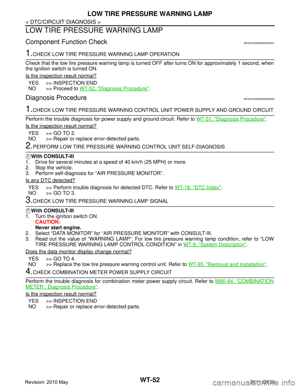
Component Function CheckINFOID:0000000006225531
1.CHECK LOW TIRE PRESSURE WARNING LAMP OPERATION
Check that the low tire pressure warning lamp is tu rned OFF after turns ON for approximately 1 second, when
the ignition switch is turned ON.
Is the inspection result normal?
YES >> INSPECTION END
NO >> Proceed to WT-52, "
Diagnosis Procedure".
Diagnosis ProcedureINFOID:0000000006225532
1.CHECK LOW TIRE PRESSURE WARNING CONT ROL UNIT POWER SUPPLY AND GROUND CIRCUIT
Perform the trouble diagnosis for power supply and ground circuit. Refer to WT-51, "
Diagnosis Procedure".
Is the inspection result normal?
YES >> GO TO 2.
NO >> Repair or replace error-detected parts.
2.PERFORM LOW TIRE PRESSURE WARNI NG CONTROL UNIT SELF-DIAGNOSIS
With CONSULT-III
1. Drive for several minutes at a s peed of 40 km/h (25 MPH) or more.
2. Stop the vehicle.
3. Perform self-diagnosis for “AIR PRESSURE MONITOR”.
Is any DTC detected?
YES >> Perform trouble diagnosis for detected DTC. Refer to WT-18, "DTC Index".
NO >> GO TO 3.
3.CHECK LOW TIRE PRESSURE WARNING LAMP SIGNAL
With CONSULT-III
1. Turn the ignition switch ON.
CAUTION:
Never start engine.
2. Select “DATA MONITOR” for “AIR PR ESSURE MONITOR” with CONSULT-III.
3. Read out the value of “WARNING LAMP”. For low tire pressure warning lamp condition, refer to “LOW TIRE PRESSURE WARNING LA MP CONTROL CONDITION” in WT-9, "
System Description".
Does the data monitor display change normal?
YES >> GO TO 4.
NO >> Replace the low tire pressure warning control unit. Refer to WT-65, "
Removal and Installation".
4.CHECK COMBINATION METER POWER SUPPLY CIRCUIT
Perform the trouble diagnosis for combination meter power supply circuit. Refer to MWI-64, "
COMBINATION
METER : Diagnosis Procedure".
Is the inspection result normal?
YES >> INSPECTION END
NO >> Repair or replace error-detected parts.
Revision: 2010 May2011 QX56
Page 5504 of 5598
WT-54
< SYMPTOM DIAGNOSIS >
TPMS SYMPTOMS
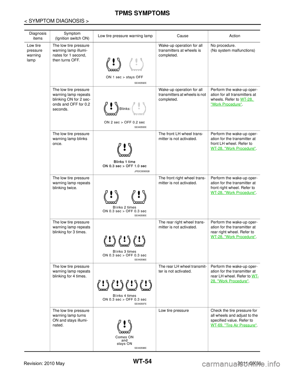
Diagnosis items Symptom
(Ignition switch ON) Low tire pressure wa
rning lamp Cause Action
Low tire
pressure
warning
lamp The low tire pressure
warning lamp illumi-
nates for 1 second,
then turns OFF. Wake-up operation for all
transmitters at wheels is
completed.
No procedure.
(No system malfunctions)
The low tire pressure
warning lamp repeats
blinking ON for 2 sec-
onds and OFF for 0.2
seconds. Wake-up operation for all
transmitters at wheels is not
completed.
Perform the wake-up oper-
ation for all transmitters at
wheels. Refer to
WT-28,
"Work Procedure".
The low tire pressure
warning lamp blinks
once. The front LH wheel trans-
mitter is not activated.
Perform the wake-up oper-
ation for the transmitter at
front LH wheel. Refer to
WT-28, "
Work Procedure".
The low tire pressure
warning lamp repeats
blinking twice. The front right wheel trans-
mitter is not activated.
Perform the wake-up oper-
ation for the transmitter at
front right wheel. Refer to
WT-28, "
Work Procedure".
The low tire pressure
warning lamp repeats
blinking for 3 times. The rear right wheel trans-
mitter is not activated.
Perform the wake-up oper-
ation for the transmitter at
rear right wheel. Refer to
WT-28, "
Work Procedure".
The low tire pressure
warning lamp repeats
blinking for 4 times. The rear LH wheel transmit-
ter is not activated.
Perform the wake-up oper-
ation for the transmitter at
rear LH wheel. Refer to
WT-
28, "Work Procedure".
The low tire pressure
warning lamp turns
ON and stays illumi-
nated. Low tire pressure Check
the tire pressure for
all wheels and adjust to the
specified value. Refer to
WT-69, "
Tire Air Pressure".
SEIA0592E
SEIA0593E
JPEIC0090GB
SEIA0595E
SEIA0596E
SEIA0597E
SEIA0598E
Revision: 2010 May2011 QX56
Page 5505 of 5598
TPMS SYMPTOMSWT-55
< SYMPTOM DIAGNOSIS >
C
DF
G H
I
J
K L
M A
B
WT
N
O P
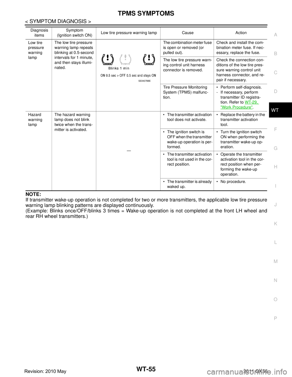
NOTE:
If transmitter wake-up operation is not completed for tw o or more transmitters, the applicable low tire pressure
warning lamp blinking patterns are displayed continuously.
(Example: Blinks once/OFF/blinks 3 times = Wake-up operation is not completed at the front LH wheel and
rear RH wheel transmitters.)
Low tire
pressure
warning
lamp The low tire pressure
warning lamp repeats
blinking at 0.5-second
intervals for 1 minute,
and then stays illumi-
nated. The combination meter fuse
is open or removed (or
pulled out).
Check and install the com-
bination meter fuse. If nec-
essary, replace the fuse.
The low tire pr essure warn-
ing control unit harness
connector is removed. Check the connection con-
ditions of the low tire pres-
sure warning
control unit
harness connector, and re-
pair if necessary.
Tire Pressure Monitoring
System (TPMS) malfunc-
tion. Perform self-diagnosis.
- If necessary, perform
transmitter ID registra-
tion. Refer to WT-29,
"Work Procedure".
Hazard
warning
lamp The hazard warning
lamp does not blink
twice when the trans-
mitter is activated.
— The transmitter activation
tool does not activate. Replace the battery in the
transmitter activation
tool.
The ignition switch is OFF when the transmitter
wake-up operation is per-
formed. Turn the ignition switch
ON when performing the
transmitter wake-up op-
eration.
The transmitter activation tool is not used in the cor-
rect position. Operate the transmitter
activation tool in the cor-
rect position when per-
forming the wake-up
operation.
The transmitter is already waked up. No procedure.
Diagnosis
items Symptom
(Ignition switch ON) Low tire pressure wa
rning lamp Cause Action
SEIA0788E
Revision: 2010 May2011 QX56
Page 5506 of 5598

WT-56
< SYMPTOM DIAGNOSIS >
LOW TIRE PRESSURE WARNING LAMP DOES NOT TURN ON
LOW TIRE PRESSURE WARNING LAMP DOES NOT TURN ON
DescriptionINFOID:0000000006225534
The low tire pressure warning lamp does not illuminate when the ignition switch is turned ON.
NOTE:
The low tire pressure warning lamp illuminates for approximately 1 second and then turns OFF when the igni-
tion switch is turned ON. This is to check that no abnorma l condition is present in the tire pressure monitoring
system.
The lamp bulb may be burnt out or the tire pressure monitoring system may be malfunctioning if the low tire
pressure warning lamp does not illuminate when the ignition switch is turned ON.
Diagnosis ProcedureINFOID:0000000006225535
1.CHECK LOW TIRE PRESSURE WARNING LAMP
Perform trouble diagnosis for the low tire pressure warning lamp. Refer to WT-52, "
Diagnosis Procedure".
Is the inspection result normal?
YES >> Check each harness connector pin terminal for malfunction or disconnection.
NO >> Repair or replace error-detected parts.
Revision: 2010 May2011 QX56
Page 5507 of 5598
LOW TIRE PRESSURE WARNING LAMP DOES NOT TURN OFFWT-57
< SYMPTOM DIAGNOSIS >
C
DF
G H
I
J
K L
M A
B
WT
N
O P
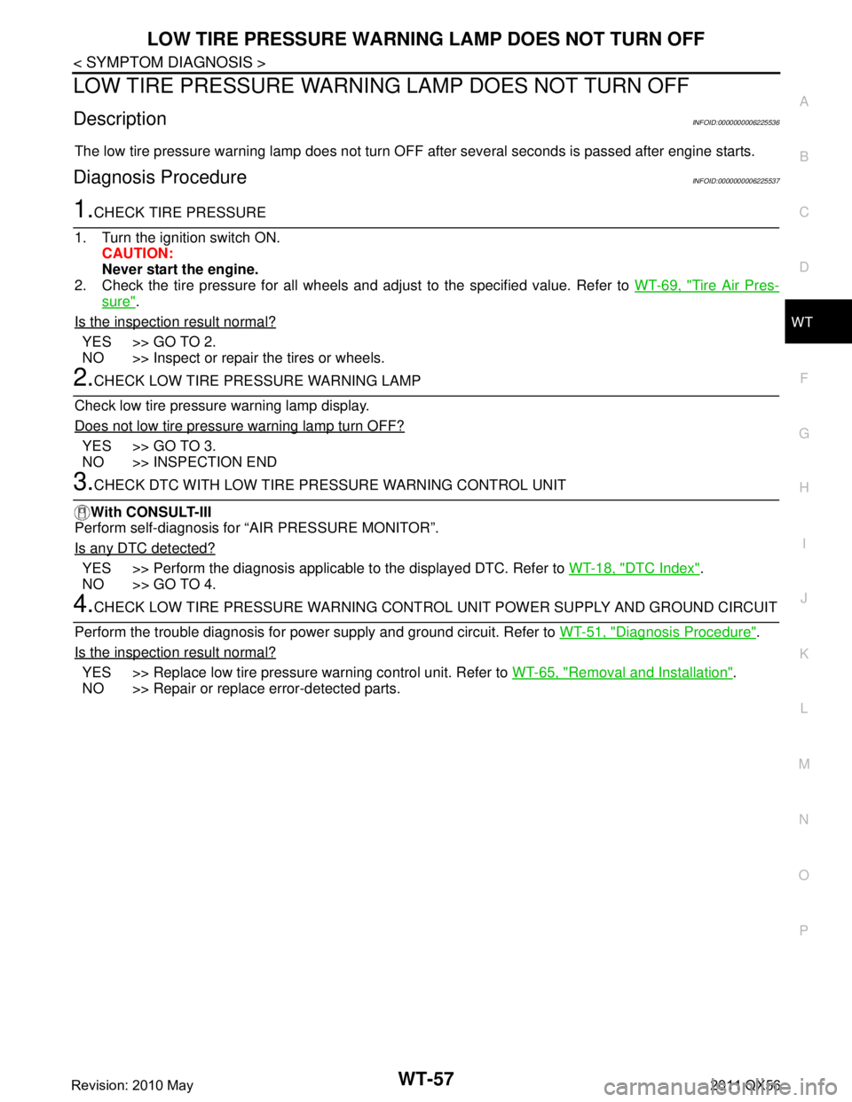
LOW TIRE PRESSURE WARNING LAMP DOES NOT TURN OFF
DescriptionINFOID:0000000006225536
The low tire pressure warning lamp does not turn OFF after several seconds is passed after engine starts.
Diagnosis ProcedureINFOID:0000000006225537
1.CHECK TIRE PRESSURE
1. Turn the ignition switch ON. CAUTION:
Never start the engine.
2. Check the tire pressure for all wheels and adjust to the specified value. Refer to WT-69, "
Tire Air Pres-
sure".
Is the inspection result normal?
YES >> GO TO 2.
NO >> Inspect or repair the tires or wheels.
2.CHECK LOW TIRE PRE SSURE WARNING LAMP
Check low tire pressure warning lamp display.
Does not low tire pressure warning lamp turn OFF?
YES >> GO TO 3.
NO >> INSPECTION END
3.CHECK DTC WITH LOW TIRE PR ESSURE WARNING CONTROL UNIT
With CONSULT-III
Perform self-diagnosis for “AIR PRESSURE MONITOR”.
Is any DTC detected?
YES >> Perform the diagnosis applicable to the displayed DTC. Refer to WT-18, "DTC Index".
NO >> GO TO 4.
4.CHECK LOW TIRE PRESSURE WARNING CONT ROL UNIT POWER SUPPLY AND GROUND CIRCUIT
Perform the trouble diagnosis for power supply and ground circuit. Refer to WT-51, "
Diagnosis Procedure".
Is the inspection result normal?
YES >> Replace low tire pressure warning control unit. Refer to WT-65, "Removal and Installation".
NO >> Repair or replace error-detected parts.
Revision: 2010 May2011 QX56