2011 INFINITI QX56 oil reset
[x] Cancel search: oil resetPage 3769 of 5598

MWI-26
< SYSTEM DESCRIPTION >
SYSTEM
The combination meter judges showing/hiding of “other warning”, according to the signals below:
Meter Illumination Level Indication
When receiving the following signals, the combination meter causes an interrupt on the information display to
indicate an illumination level.
WARNING CHECK INDICATION
The combination meter can cause an interrupt on the information display to indicate a warning, based onsignals received from each unit and switch.
The indicated warning can be checked with “WARNING” during the satisfaction of an interrupt indication
condition for each warning.
SETTING
Warning indication timing and time can be set.
Alert
Setting values for travel time, and low ambient te mperature can be adjusted to meet the user's needs.
Maintenance
Setting values for engine oil, oil filter, tire, and other maintenance items can be adjusted to meet the user's
needs.
Options
Setting values for unit and effect items can be adjusted to meet the user's needs.
Operating condition
Ignition switch ON
Mileage More than value set in “SETTING”
Signal name Signal path
Ignition signal —
Vehicle speed signal ABS actuator and electric unit (control unit) Combination meter
Signal name Signal path
Ignition signal —
Illumination control switch signal (+) Trip reset and illumination control switch Combination meter
Illumination control switch signal ( −)
Setting item Setting range Setting unit
Alert Timer No setting, 0.5 h - 6 h 0.5 h
ICY ON/OFF —
Setting item Setting range
Maintenance Tire
No setting, 500 km - 30,000 km
(No setting, 250 mile - 18,500 mile)
Filter No setting, 500 km - 30,000 km
(No setting, 250 mile - 18,500 mile)
Oil No setting, 500 km - 30,000 km
(No setting, 250 mile - 18,500 mile)
Other No setting, 500 km - 30,000 km
(No setting, 250 mile - 18,500 mile)
Revision: 2010 May2011 QX56
Page 3772 of 5598

MWI
DIAGNOSIS SYSTEM (COMBINATION METER)
MWI-29
< SYSTEM DESCRIPTION >
C
D E
F
G H
I
J
K L
M B A
O P
DIAGNOSIS SYSTEM (COMBINATION METER)
On Board Diagnosis FunctionINFOID:0000000006221719
ON BOARD DIAGNOSIS ITEM
The combination meter allows the following diagnosis items with the on-board diagnosis function.
METHOD OF STARTING
1. Turn ignition switch OFF.
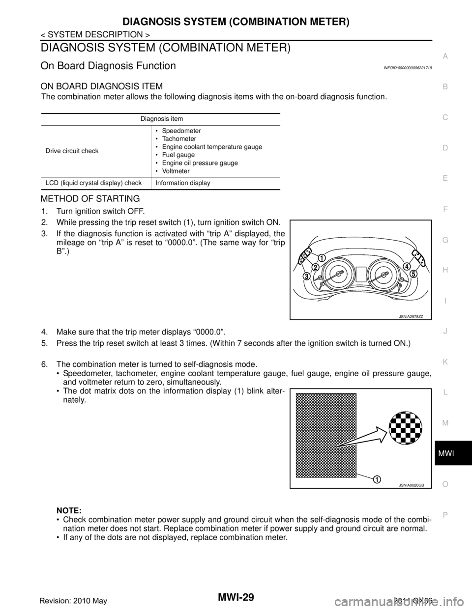
2. While pressing the trip reset switch (1), turn ignition switch ON.
3. If the diagnosis function is activated with “trip A” displayed, the
mileage on “trip A” is reset to “0000.0”. (The same way for “trip
B”.)
4. Make sure that the trip meter displays “0000.0”.
5. Press the trip reset switch at least 3 times. (Wit hin 7 seconds after the ignition switch is turned ON.)
6. The combination meter is turned to self-diagnosis mode. Speedometer, tachometer, engine coolant temper ature gauge, fuel gauge, engine oil pressure gauge,
and voltmeter return to zero, simultaneously.
The dot matrix dots on the information display (1) blink alter-
nately.
NOTE:
Check combination meter power supply and ground circuit when the self-diagnosis mode of the combi- nation meter does not start. Replace combination meter if power supply and ground circuit are normal.
If any of the dots are not displayed, replace combination meter.
Diagnosis item
Drive circuit check Speedometer
Tachometer
Engine coolant temperature gauge
Fuel gauge
Engine oil pressure gauge
Voltmeter
LCD (liquid crystal display) check Information display
JSNIA2978ZZ
JSNIA0020GB
Revision: 2010 May2011 QX56
Page 3785 of 5598

MWI-42
< ECU DIAGNOSIS INFORMATION >
COMBINATION METER
Fail-Safe
INFOID:0000000006221722
FA I L - S A F E
The combination meter activates the fail-safe contro l if CAN communication with each unit is malfunctioning.
37
(R/Y) Ground Non-manual mode signal Input Ignition
switch
ONSelector manual mode po-
sition
12 V
Other than the above 0 V
38
(L/W) Ground Manual mode shift down
signal InputIgnition
switch
ON Selector lever DOWN oper-
ation
0 V
Other than the above 12 V
39
(Y/B) Ground Manual mode shift up sig-
nal InputIgnition
switch
ON Selector lever UP operation 0 V
Other than the above 12 V
40
(G/W) Ground Manual mode signal Input Ignition
switch
ONSelector manual mode po-
sition
0 V
Other than the above 12 V
Te r m i n a l N o .
(Wire color) Description
ConditionVa l u e
(Approx.)
+ – Signal name Input/
Output
Function Specifications
Speedometer
Reset to zero by suspending communication.
Tachometer
Engine coolant temperature gauge
Engine oil pressure gauge
Illumination control When suspending communication, changes to nighttime mode.
Information display Odo/trip meter An indicated value is maintained at communications blackout.
Shift position indicator The display turns OFF by suspending communication.
Door open warning The display turns OFF by suspending communication.
Buzzer The buzzer turns OFF by suspending communication.
Revision: 2010 May2011 QX56
Page 4781 of 5598

SR-18
< REMOVAL AND INSTALLATION >
FRONT PASSENGER AIR BAG MODULE
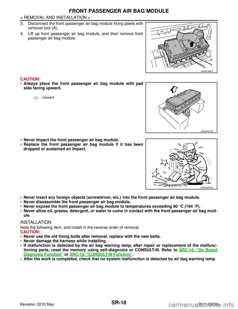
3. Disconnect the front passenger air bag module fixing pawls withremover tool (A).
4. Lift up front passenger air bag module, and then remove front passenger air bag module.
CAUTION:
Always place the front passenger air bag module with pad side facing upward.
Never impact the front passenger air bag module.
Replace the front passenger air bag module if it has been dropped or sustained an impact.
Never insert any foreign objects (screwdriver, etc.) into the front passenger air bag module.
Never disassemble the front passenger air bag module.
Never expose the front passenger air bag module to temperatures exceeding 90 °C (194 °F).
Never allow oil, grease, detergent, or water to co me in contact with the front passenger air bag mod-
ule.
INSTALLATION
Note the following item, and install in the reverse order of removal.
CAUTION:
Never use the old fixing bolts afte r removal, replace with the new bolts.
Never damage the harness while installing.
If malfunction is detected by the air bag warnin g lamp, after repair or replacement of the malfunc-
tioning parts, reset the memory using sel f-diagnosis or CONSULT-III. Refer to SRC-14, "
On Board
Diagnosis Function" or SRC-19, "CONSULT-III Function".
After the work is completed, check that no system malfunction is detected by air bag warning lamp.
JMHIA1488ZZ
: Upward
JMHIA0661ZZ
JMHIA0009ZZ
Revision: 2010 May2011 QX56
Page 5411 of 5598

WCS
SYSTEMWCS-7
< SYSTEM DESCRIPTION >
C
DE
F
G H
I
J
K L
M B A
O P
WARNING CHIME SYSTEM : Fail-SafeINFOID:0000000006369726
FA I L - S A F E
The combination meter activates the fail-safe contro l if CAN communication with each unit is malfunctioning.
Seat belt warning chimeThe warning chime sounds when the driver
seat belt is unfastened with the ignition switch
in ON position. BCMWCS-11,
"SEAT BELT
WARNING
CHIME : Sys-
tem Descrip-
tion"
Parking brake release warning chime
The warning chime sounds when the ignition
switch is in ON position with the parking brake
in operation and the vehicle speed 7 km/h (4.3
MPH) or more. Combination meterWCS-12,
"PA R K I N G
BRAKE RE-
LEASE WARN-
ING CHIME :
System De-
scription"
Warning functions Out line Warning judgment unit Refer to
Function Specifications
Speedometer
Reset to zero by suspending communication.
Tachometer
Engine coolant temperature gauge
Engine oil pressure gauge
Illumination control When suspending communication, changes to nighttime mode.
Information display Odo/trip meter An indicated value is maintained at communications blackout.
Shift position indicator The display turns OFF by suspending communication.
Door open warning The display turns OFF by suspending communication.
Buzzer The buzzer turns OFF by suspending communication.
Revision: 2010 May2011 QX56
Page 5433 of 5598

WCS
COMBINATION METERWCS-29
< ECU DIAGNOSIS INFORMATION >
C
DE
F
G H
I
J
K L
M B A
O P
Fail-SafeINFOID:0000000006222689
FA I L - S A F E
The combination meter activates the fail-safe contro l if CAN communication with each unit is malfunctioning.
37
(R/Y) Ground Non-manual mode signal Input Ignition
switch
ONSelector manual mode po-
sition
12 V
Other than the above 0 V
38
(L/W) Ground Manual mode shift down
signal InputIgnition
switch
ON Selector lever DOWN oper-
ation
0 V
Other than the above 12 V
39
(Y/B) Ground Manual mode shift up sig-
nal InputIgnition
switch
ON Selector lever UP operation 0 V
Other than the above 12 V
40
(G/W) Ground Manual mode signal Input Ignition
switch
ONSelector manual mode po-
sition
0 V
Other than the above 12 V
Te r m i n a l N o .
(Wire color) Description
ConditionVa l u e
(Approx.)
+ – Signal name Input/
Output
Function Specifications
Speedometer
Reset to zero by suspending communication.
Tachometer
Engine coolant temperature gauge
Engine oil pressure gauge
Illumination control When suspending communication, changes to nighttime mode.
Information display Odo/trip meter An indicated value is maintained at communications blackout.
Shift position indicator The display turns OFF by suspending communication.
Door open warning The display turns OFF by suspending communication.
Buzzer The buzzer turns OFF by suspending communication.
Revision: 2010 May2011 QX56