2011 INFINITI QX56 engine oil
[x] Cancel search: engine oilPage 1502 of 5598

DEF-10
< SYSTEM DESCRIPTION >
DIAGNOSIS SYSTEM (IPDM E/R)
DIAGNOSIS SYSTEM (IPDM E/R)
Diagnosis DescriptionINFOID:0000000006349776
AUTO ACTIVE TEST
Description
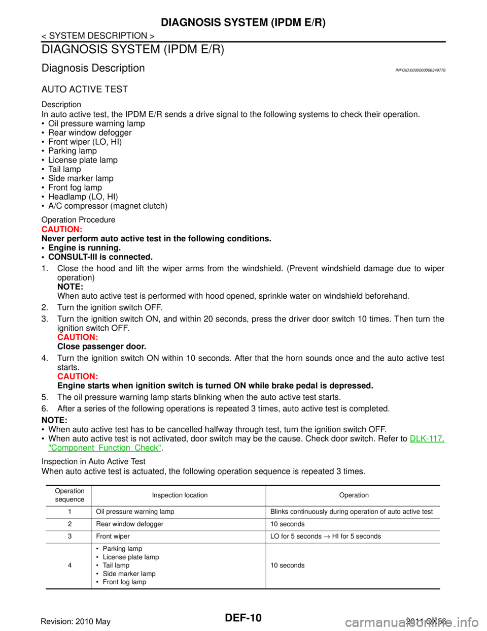
In auto active test, the IPDM E/R sends a drive signal to the following systems to check their operation.
Oil pressure warning lamp
Rear window defogger
Front wiper (LO, HI)
Parking lamp
License plate lamp
Tail lamp
Side marker lamp
Front fog lamp
Headlamp (LO, HI)
A/C compressor (magnet clutch)
Operation Procedure
CAUTION:
Never perform auto active test in the following conditions.
Engine is running.
CONSULT-III is connected.
1. Close the hood and lift the wiper arms from the windshield. (Prevent windshield damage due to wiper
operation)
NOTE:
When auto active test is performed with hood opened, sprinkle water on windshield beforehand.
2. Turn the ignition switch OFF.
3. Turn the ignition switch ON, and within 20 seconds, pr ess the driver door switch 10 times. Then turn the
ignition switch OFF.
CAUTION:
Close passenger door.
4. Turn the ignition switch ON within 10 seconds. Af ter that the horn sounds once and the auto active test
starts.
CAUTION:
Engine starts when igniti on switch is turned ON while brake pedal is depressed.
5. The oil pressure warning lamp starts blinking when the auto active test starts.
6. After a series of the following operations is repeated 3 times, auto active test is completed.
NOTE:
When auto active test has to be cancelled halfway through test, turn the ignition switch OFF.
When auto active test is not activated, door swit ch may be the cause. Check door switch. Refer to DLK-117,
"ComponentFunctionCheck".
Inspection in Auto Active Test
When auto active test is actuated, the following operation sequence is repeated 3 times.
Operation
sequence Inspection location Operation
1 Oil pressure warning lamp Blinks continuously during operation of auto active test
2 Rear window defogger 10 seconds
3 Front wiper LO for 5 seconds → HI for 5 seconds
4 Parking lamp
License plate lamp
Tail lamp
Side marker lamp
Front fog lamp 10 seconds
Revision: 2010 May2011 QX56
Page 1788 of 5598

DLK-252
< REMOVAL AND INSTALLATION >
CAB MOUNTING INSULATOR
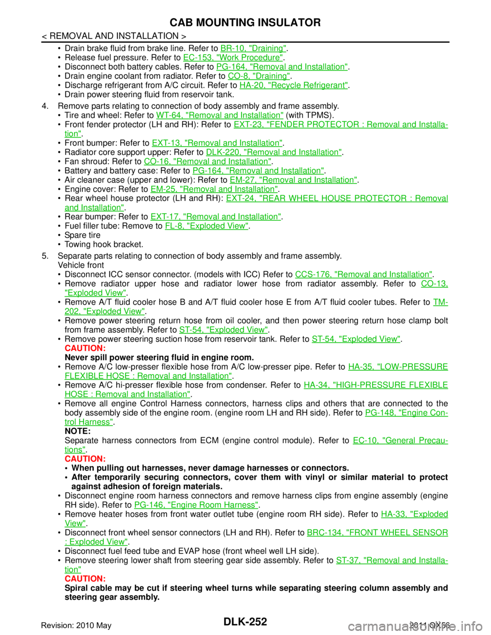
Drain brake fluid from brake line. Refer to BR-10, "Draining".
Release fuel pressure. Refer to EC-153, "
Work Procedure".
Disconnect both battery cables. Refer to PG-164, "
Removal and Installation".
Drain engine coolant from radiator. Refer to CO-8, "
Draining".
Discharge refrigerant from A/C circuit. Refer to HA-20, "
Recycle Refrigerant".
Drain power steering fluid from reservoir tank.
4. Remove parts relating to connection of body assembly and frame assembly. Tire and wheel: Refer to WT-64, "
Removal and Installation" (with TPMS).
Front fender protector (LH and RH): Refer to EXT-23, "
FENDER PROTECTOR : Removal and Installa-
tion".
Front bumper: Refer to EXT-13, "
Removal and Installation".
Radiator core support upper: Refer to DLK-220, "
Removal and Installation".
Fan shroud: Refer to CO-16, "
Removal and Installation".
Battery and battery case: Refer to PG-164, "
Removal and Installation".
Air cleaner case (upper and lower): Refer to EM-27, "
Removal and Installation".
Engine cover: Refer to EM-25, "
Removal and Installation".
Rear wheel house protector (LH and RH): EXT-24, "
REAR WHEEL HOUSE PROTECTOR : Removal
and Installation".
Rear bumper: Refer to EXT-17, "
Removal and Installation".
Fuel filler tube: Remove to FL-8, "
Exploded View".
Spare tire
Towing hook bracket.
5. Separate parts relating to connection of body assembly and frame assembly. Vehicle front
Disconnect ICC sensor connector. (models with ICC) Refer to CCS-176, "
Removal and Installation".
Remove radiator upper hose and radiator lower hose from radiator assembly. Refer to CO-13,
"Exploded View".
Remove A/T fluid cooler hose B and A/T fluid cooler hose E from A/T fluid cooler tubes. Refer to TM-
202, "Exploded View".
Remove power steering return hose from oil cooler, and then power steering return hose clamp bolt from frame assembly. Refer to ST-54, "
Exploded View".
Remove power steering suction hose from reservoir tank. Refer to ST-54, "
Exploded View".
CAUTION:
Never spill power steering fluid in engine room.
Remove A/C low-presser flexible hose from A/C low-presser pipe. Refer to HA-35, "
LOW-PRESSURE
FLEXIBLE HOSE : Removal and Installation".
Remove A/C hi-presser flexible hose from condenser. Refer to HA-34, "
HIGH-PRESSURE FLEXIBLE
HOSE : Removal and Installation".
Remove all engine Control Harness connectors, har ness clips and others that are connected to the
body assembly side of the engine room. (engine room LH and RH side). Refer to PG-148, "
Engine Con-
trol Harness".
NOTE:
Separate harness connectors from ECM (engine control module). Refer to EC-10, "
General Precau-
tions".
CAUTION:
When pulling out harnesses, never damage harnesses or connectors.
After temporarily securing connectors, cover th em with vinyl or similar material to protect
against adhesion of foreign materials.
Disconnect engine room harness connectors and remo ve harness clips from engine assembly (engine
RH side). Refer to PG-146, "
Engine Room Harness".
Remove heater hoses from front water outlet tube (engine room RH side). Refer to HA-33, "
Exploded
View".
Disconnect front wheel sensor connectors (LH and RH). Refer to BRC-134, "
FRONT WHEEL SENSOR
: Exploded View".
Disconnect fuel feed tube and EVAP hos e (front wheel well LH side).
Remove steering lower shaft from steering gear side assembly. Refer to ST-37, "
Removal and Installa-
tion"
CAUTION:
Spiral cable may be cut if steering wheel turns while separating steering column assembly and
steering gear assembly.
Revision: 2010 May2011 QX56
Page 1789 of 5598

CAB MOUNTING INSULATORDLK-253
< REMOVAL AND INSTALLATION >
C
DE
F
G H
I
J
L
M A
B
DLK
N
O P
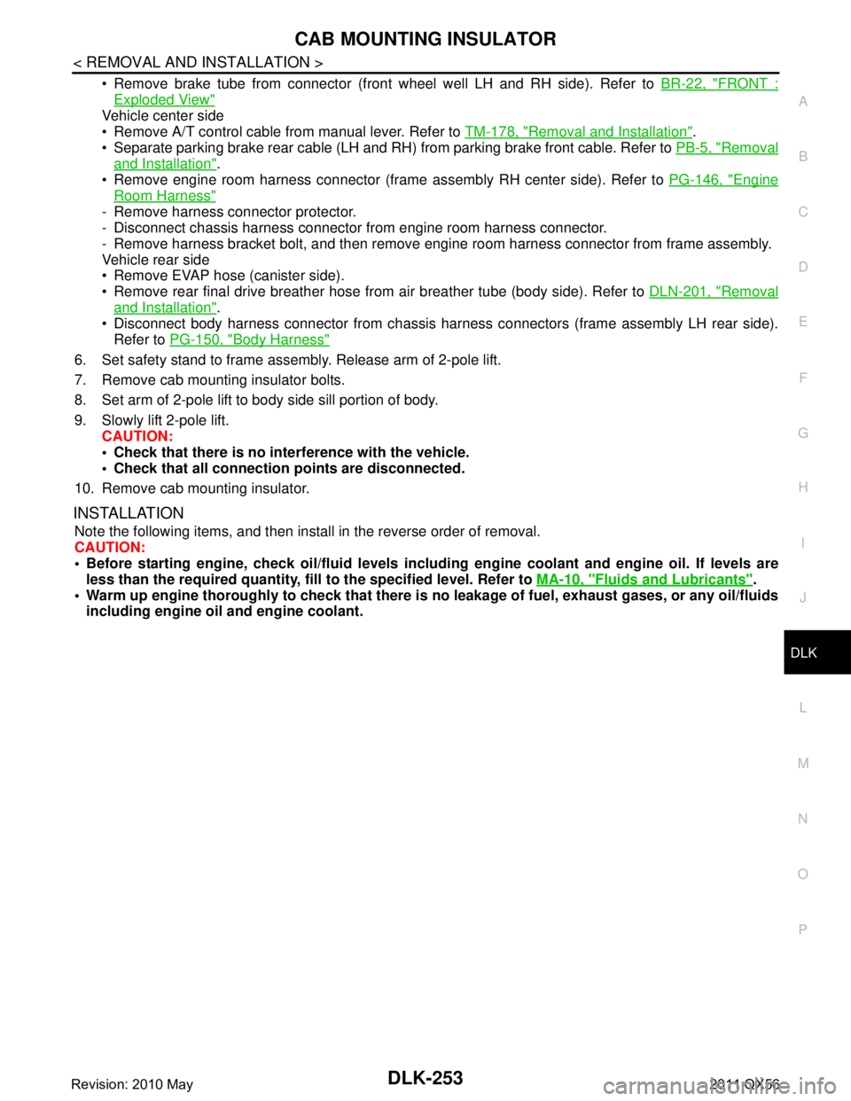
Remove brake tube from connector (front wheel well LH and RH side). Refer to BR-22, "FRONT :
Exploded View"
Vehicle center side
Remove A/T control cable from manual lever. Refer to TM-178, "
Removal and Installation".
Separate parking brake rear cable (LH and RH) from parking brake front cable. Refer to PB-5, "
Removal
and Installation".
Remove engine room harness connector (frame assembly RH center side). Refer to PG-146, "
Engine
Room Harness"
- Remove harness connector protector.
- Disconnect chassis harness connector from engine room harness connector.
- Remove harness bracket bolt, and then remove engi ne room harness connector from frame assembly.
Vehicle rear side
Remove EVAP hose (canister side).
Remove rear final drive breather hose from air breather tube (body side). Refer to DLN-201, "
Removal
and Installation".
Disconnect body harness connector from chassis harness connectors (frame assembly LH rear side).
Refer to PG-150, "
Body Harness"
6. Set safety stand to frame assembly. Release arm of 2-pole lift.
7. Remove cab mounting insulator bolts.
8. Set arm of 2-pole lift to body side sill portion of body.
9. Slowly lift 2-pole lift.
CAUTION:
Check that there is no inte rference with the vehicle.
Check that all connection points are disconnected.
10. Remove cab mounting insulator.
INSTALLATION
Note the following items, and then install in the reverse order of removal.
CAUTION:
Before starting engine, check oil/fl uid levels including engine coolant and engine oil. If levels are
less than the required quantity, fill to the specified level. Refer to MA-10, "
Fluids and Lubricants".
Warm up engine thoroughly to check that there is no leakage of fuel, exhaust gases, or any oil/fluids
including engine oil and engine coolant.
Revision: 2010 May2011 QX56
Page 1825 of 5598
![INFINITI QX56 2011 Factory Service Manual
DIAGNOSIS SYSTEM (TRANSFER CONTROL UNIT)
DLN-23
< SYSTEM DESCRIPTION > [TRANSFER: ATX90A]
C
EF
G H
I
J
K L
M A
B
DLN
N
O P
WORK SUPPORT
*: “LOCK SLEEVE SENSOR” means transfer lock position sensor INFINITI QX56 2011 Factory Service Manual
DIAGNOSIS SYSTEM (TRANSFER CONTROL UNIT)
DLN-23
< SYSTEM DESCRIPTION > [TRANSFER: ATX90A]
C
EF
G H
I
J
K L
M A
B
DLN
N
O P
WORK SUPPORT
*: “LOCK SLEEVE SENSOR” means transfer lock position sensor](/manual-img/42/57033/w960_57033-1824.png)
DIAGNOSIS SYSTEM (TRANSFER CONTROL UNIT)
DLN-23
< SYSTEM DESCRIPTION > [TRANSFER: ATX90A]
C
EF
G H
I
J
K L
M A
B
DLN
N
O P
WORK SUPPORT
*: “LOCK SLEEVE SENSOR” means transfer lock position sensor.
VHCL/S SEN-RR [km/h] X Wheel speed (rear) average calculated by
transfer control.
ENG SPEED [rpm] X Engine status via CAN communication line is
displayed.
INTERNL SPEED SEN [count] X Transfer internal speed sensor status is dis-
played.
TRANSFER TORQUE [Nm] X Commanded transfer communication torque is
displayed.
UNIT PARAMETER [A1 - A9, B1 - B9, C1 - C9, D1
- D9, E1 - E9, F1 - F9, G1 - G9, H1 - H9, J1 - J9] Unit parameter of transfer recognized by trans-
fer control unit is displayed.
Monitor item (Unit)
SELECT MONITOR ITEM
Remarks
ECU INPUT
SIGNALS MAIN SIG-
NALS
Function Description
UNIT CHARACTERISTIC WRITE Writes the unit parameter of transfer to transfer control unit.
START CALIBRATION Perform initial calibration of transfer control unit.
LOCK SLEEVE SENSOR
* INITIALIZE Format learning the transfer lock position sensor written to transfer control unit.
LOCK SLEEVE SENSOR
* LEARNING Perform learning the transfer lock position sensor.
OIL DETERIORATION INFO RESET Format the transfer fl uid viscosity written to transfer control unit.
Revision: 2010 May2011 QX56
Page 1831 of 5598
![INFINITI QX56 2011 Factory Service Manual
TRANSFER CONTROL UNITDLN-29
< ECU DIAGNOSIS INFORMATION > [TRANSFER: ATX90A]
C
EF
G H
I
J
K L
M A
B
DLN
N
O P
DTC Inspection Priority ChartINFOID:0000000006222229
If some DTCs are displayed at the sa INFINITI QX56 2011 Factory Service Manual
TRANSFER CONTROL UNITDLN-29
< ECU DIAGNOSIS INFORMATION > [TRANSFER: ATX90A]
C
EF
G H
I
J
K L
M A
B
DLN
N
O P
DTC Inspection Priority ChartINFOID:0000000006222229
If some DTCs are displayed at the sa](/manual-img/42/57033/w960_57033-1830.png)
TRANSFER CONTROL UNITDLN-29
< ECU DIAGNOSIS INFORMATION > [TRANSFER: ATX90A]
C
EF
G H
I
J
K L
M A
B
DLN
N
O P
DTC Inspection Priority ChartINFOID:0000000006222229
If some DTCs are displayed at the same time, per form inspections one by one based on the following priority
chart.
DTC IndexINFOID:0000000006222230
Priority Detected items (DTC)
1 U1000 CAN COMM CIRCUIT
U1010 CONTROL UNIT (CAN)
2 P1802 CONTROL UNIT 1
P1803 CONTROL UNIT 2
P1804 CONTROL UNIT 3
P1809 CONTROL UNIT 4
P180C SEN POWER SUPPLY (5V)
P180E SEN POWER SUPPLY (8V)
P1811 BATTERY VOLTAGE
P181B INCOMP SELFSHUT
P181C MOTOR POWER SUPPLY
P181F INCOMP CALIBRATION
3 P1807 VECL SPEED SEN-AT
P1808 VECL SPEED SEN-ABS
P1816 PNP SW/CIRC
P181E ST ANGLE SEN SIG
P1820 ENGINE SPEED SIG
P1829 THROTTLE POSI SEN
P1830 ABS OP SIG
P1831 VDC OP SIG
P1832 TCS OP SIG
4 P180D ROTARY POSITION SEN
P1813 4WD MODE SW
P181A MOTOR TEMP SEN
P1826 OIL TEMP SEN
P182A HI-LO POSITION SEN
P182B LOCK POSITION SEN
5 P180F MOTOR SYSTEM
P1817 SHIFT ACTUATOR
DTC Display Items Reference
P1802 CONTROL UNIT 1 DLN-51, "
DTC Logic"
P1803 CONTROL UNIT 2DLN-51, "DTC Logic"
P1804 CONTROL UNIT 3DLN-51, "DTC Logic"
P1807 VHCL SPEED SEN-ATDLN-52, "DTC Logic"
P1808 VHCL SPEED SEN-ABSDLN-53, "DTC Logic"
P1809 CONTROL UNIT 4DLN-51, "DTC Logic"
P180C SEN POWER SUPPLY (5V) DLN-54, "DTC Logic"
P180D ROTARY POSITION SENDLN-57, "DTC Logic"
P180E SEN POWER SUPPLY (8V)DLN-59, "DTC Logic"
P180F MOTOR SYSTEMDLN-61, "DTC Logic"
P1811 BATTERY VOLTAGEDLN-64, "DTC Logic"
P1813 4WD MODE SW DLN-67, "DTC Logic"
P1816 PNP SW/CIRCDLN-69, "DTC Logic"
P1817 SHIFT ACTUATORDLN-70, "DTC Logic"
P181A MOTOR TEMP SEN DLN-72, "DTC Logic"
P181B IMCOMP SELFSHUTDLN-74, "DTC Logic"
Revision: 2010 May2011 QX56
Page 1832 of 5598
![INFINITI QX56 2011 Factory Service Manual
DLN-30
< ECU DIAGNOSIS INFORMATION >[TRANSFER: ATX90A]
TRANSFER CONTROL UNIT
P181C MOTOR POWER SUPPLY
DLN-76, "DTC Logic"
P181E ST ANGLE SEN SIGDLN-77, "DTC Logic"
P181F INCOMP CALIBRATIONDLN-78, "DT INFINITI QX56 2011 Factory Service Manual
DLN-30
< ECU DIAGNOSIS INFORMATION >[TRANSFER: ATX90A]
TRANSFER CONTROL UNIT
P181C MOTOR POWER SUPPLY
DLN-76, "DTC Logic"
P181E ST ANGLE SEN SIGDLN-77, "DTC Logic"
P181F INCOMP CALIBRATIONDLN-78, "DT](/manual-img/42/57033/w960_57033-1831.png)
DLN-30
< ECU DIAGNOSIS INFORMATION >[TRANSFER: ATX90A]
TRANSFER CONTROL UNIT
P181C MOTOR POWER SUPPLY
DLN-76, "DTC Logic"
P181E ST ANGLE SEN SIGDLN-77, "DTC Logic"
P181F INCOMP CALIBRATIONDLN-78, "DTC Logic"
P1826 OIL TEMP SENDLN-80, "DTC Logic"
P1820 ENGINE SPEED SIGDLN-79, "DTC Logic"
P1829 THROTTLE POSI SENDLN-82, "DTC Logic"
P182A HI-LO POSITION SEN DLN-83, "DTC Logic"
P182B LOCK POSITION SENDLN-85, "DTC Logic"
P1830 ABS OP SIGDLN-88, "DTC Logic"
P1831 VDC OP SIGDLN-89, "DTC Logic"
P1832 TCS OP SIGDLN-90, "DTC Logic"
U1000 CAN COMM CIRCUIT DLN-91, "DTC Logic"
U1010 CONTROL UNIT (CAN)DLN-92, "DTC Logic"
DTC Display Items Reference
Revision: 2010 May2011 QX56
Page 1844 of 5598
![INFINITI QX56 2011 Factory Service Manual
DLN-42
< BASIC INSPECTION >[TRANSFER: ATX90A]
ADDITIONAL SERVICE WHEN
REPLACING TRANSFER ASSEMBLY
ADDITIONAL SERVICE WHEN REPLACING TRANSFER ASSEMBLY
DescriptionINFOID:0000000006222236
Perform writi INFINITI QX56 2011 Factory Service Manual
DLN-42
< BASIC INSPECTION >[TRANSFER: ATX90A]
ADDITIONAL SERVICE WHEN
REPLACING TRANSFER ASSEMBLY
ADDITIONAL SERVICE WHEN REPLACING TRANSFER ASSEMBLY
DescriptionINFOID:0000000006222236
Perform writi](/manual-img/42/57033/w960_57033-1843.png)
DLN-42
< BASIC INSPECTION >[TRANSFER: ATX90A]
ADDITIONAL SERVICE WHEN
REPLACING TRANSFER ASSEMBLY
ADDITIONAL SERVICE WHEN REPLACING TRANSFER ASSEMBLY
DescriptionINFOID:0000000006222236
Perform writing unit parameter, transfer fluid viscosity learning and initial calibration after replacing transfer
assembly. Refer to DLN-42, "
Work Procedure".
Work ProcedureINFOID:0000000006222237
NOTE:
In fail-safe mode, can not perform work s upport. (Except that DTC P181F is detected.)
1.WRITE UNIT PARAMETER
Perform writing unit parameter to control unit. Refer to DLN-48, "
Work Procedure".
>> GO TO 2.
2.PREPARATION BEFORE WORK
With CONSULT-III
1. Start the engine. CAUTION:
Never drive the vehicle.
2. Check “4WD MODE”, “T/M RANGE”, “COMER V HCL SPEED”, “MOTOR POWER SUP” of CONSULT-III
“DATA MONITOR” for “ALL MODE AWD/4WD”.
3. Continue the following condition more than 10 seconds.
>> GO TO 3.
3.PERFORM TRANSFER FLUID VISCOSITY LEARNING
With CONSULT-III
1. Select “OIL DETERIORATION INFO RESET” of CONSULT-III “WORK SUPPORT” for “ALL MODE AWD/
4WD”.
2. Select “Start”.
>> GO TO 4.
4.INITIAL CALIBRATION
With CONSULT-III
1. Select “START CALIBRATION” of CONSULT- III “WORK SUPPORT” for “ALL MODE AWD/4WD”.
2. Wait until the motor operation stop. (After approximately 10 seconds)
>> GO TO 5.
5.PERFORM SELF-DIAGNOSIS
With CONSULT-III
1. Erase self-diagnosis result for “ALL MODE AWD/4WD”.
2. Turn the ignition switch ON to OFF. CAUTION:
Wait for 10 seconds after turn ing ignition switch OFF.
3. Start the engine. CAUTION:
Never drive the vehicle.
4. Perform self-diagnosis for “ALL MODE AWD/4WD”.
4WD MODE : AUTO
T/M RANGE : N
COMPER VHCL SPEED : 0 km/h (Never drive the vehicle)
MOTOR POWER SUP : More than 11 V
Revision: 2010 May2011 QX56
Page 1849 of 5598
![INFINITI QX56 2011 Factory Service Manual
TRANSFER FLUID VISCOSITY LEARNINGDLN-47
< BASIC INSPECTION > [TRANSFER: ATX90A]
C
EF
G H
I
J
K L
M A
B
DLN
N
O P
TRANSFER FLUID VISCOSITY LEARNING
DescriptionINFOID:0000000006222242
Perform transfer INFINITI QX56 2011 Factory Service Manual
TRANSFER FLUID VISCOSITY LEARNINGDLN-47
< BASIC INSPECTION > [TRANSFER: ATX90A]
C
EF
G H
I
J
K L
M A
B
DLN
N
O P
TRANSFER FLUID VISCOSITY LEARNING
DescriptionINFOID:0000000006222242
Perform transfer](/manual-img/42/57033/w960_57033-1848.png)
TRANSFER FLUID VISCOSITY LEARNINGDLN-47
< BASIC INSPECTION > [TRANSFER: ATX90A]
C
EF
G H
I
J
K L
M A
B
DLN
N
O P
TRANSFER FLUID VISCOSITY LEARNING
DescriptionINFOID:0000000006222242
Perform transfer fluid viscosity learning and initial calibration after draining and refilling transfer fluid. Refer to
DLN-47, "
Work Procedure".
Work ProcedureINFOID:0000000006222243
NOTE:
In fail-safe mode, can not perform work s upport. (Except that DTC P181F is detected.)
1.PREPARATION BEFORE WORK
With CONSULT-III
1. Start the engine.
CAUTION:
Never drive the vehicle.
2. Check “4WD MODE”, “T/M RANGE”, “COMER VHCL SPEED”, “MOTOR POWER SUP” of CONSULT-III
“DATA MONITOR” for “ALL MODE AWD/4WD”.
3. Continue the following condition more than 10 seconds.
>> GO TO 2.
2.TRANSFER FLUID VISCOSITY LEARNING
With CONSULT-III
1. Select “OIL DETERIORATION INFO RESET” of CONSULT-III “WORK SUPPORT” for “ALL MODE AWD/
4WD”.
2. Select “Start”.
>> GO TO 3.
3.INITIAL CALIBRATION
With CONSULT-III
1. Select “START CALIBRATION” of CONSULT- III “WORK SUPPORT” for “ALL MODE AWD/4WD”.
2. Wait until the motor operation stop. (After approximately 10 seconds)
>> GO TO 4.
4.PERFORM SELF-DIAGNOSIS
With CONSULT-III
1. Erase self-diagnosis result for “ALL MODE AWD/4WD”.
2. Turn the ignition switch ON to OFF.
CAUTION:
Wait for 10 seconds after turning ignition switch OFF.
3. Start the engine.
CAUTION:
Never drive the vehicle.
4. Perform self-diagnosis for “ALL MODE AWD/4WD”.
Is
“DTC P181F” detected?
YES >> GO TO 1.
NO >> WORK END
4WD MODE : AUTO
T/M RANGE : N
COMPER VHCL SPEED : 0 km/h (Never drive the vehicle)
MOTOR POWER SUP : More than 11 V
Revision: 2010 May2011 QX56