2011 INFINITI QX56 ad blue
[x] Cancel search: ad bluePage 2610 of 5598
EM-48
< REMOVAL AND INSTALLATION >
FUEL INJECTOR AND FUEL TUBE
FUEL INJECTOR AND FUEL TUBE
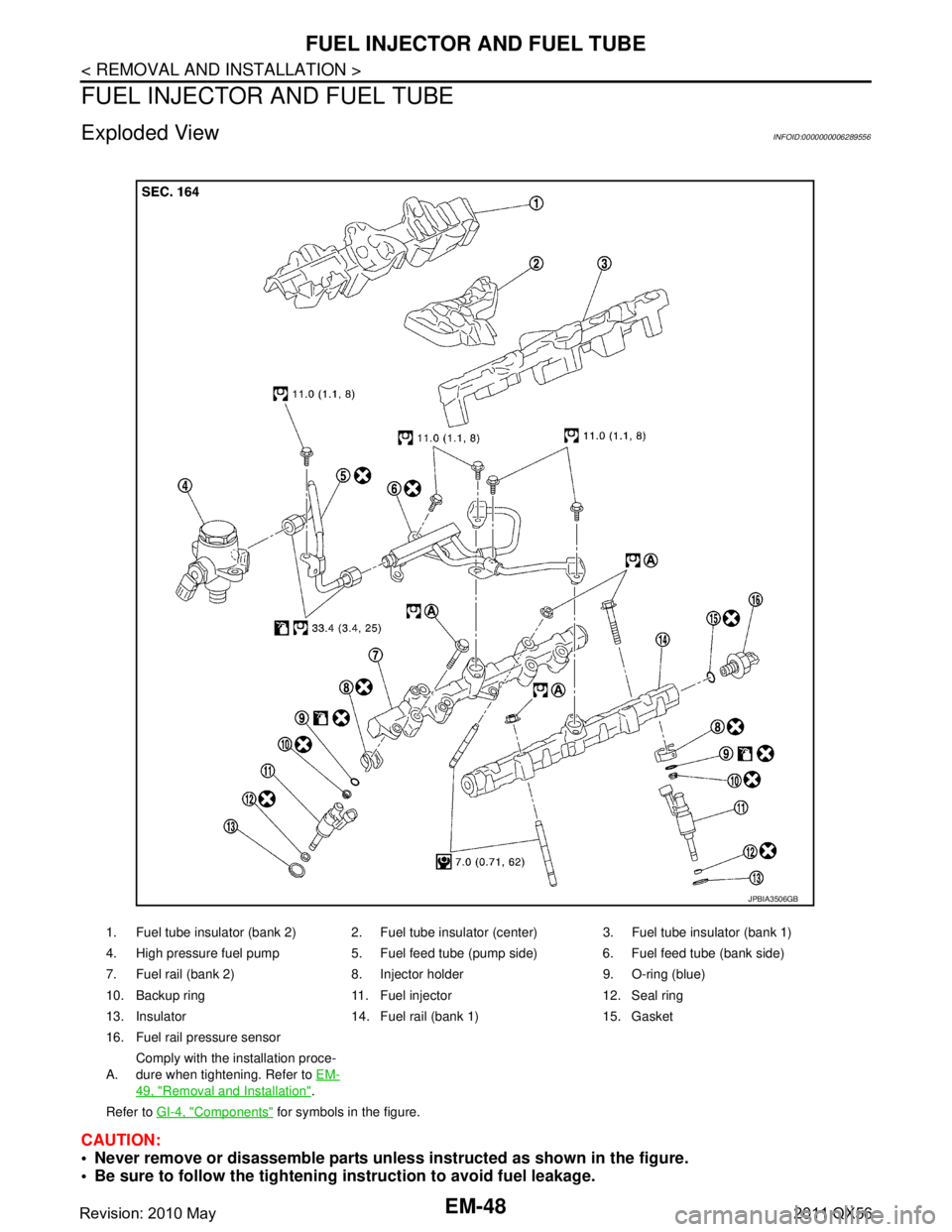
Exploded ViewINFOID:0000000006289556
CAUTION:
Never remove or disassemble parts unless instructed as shown in the figure.
Be sure to follow the tightening instruction to avoid fuel leakage.
1. Fuel tube insulator (bank 2) 2. Fuel tube insulator (center) 3. Fuel tube insulator (bank 1)
4. High pressure fuel pump 5. Fuel feed tube (pump side) 6. Fuel feed tube (bank side)
7. Fuel rail (bank 2) 8. Injector holder 9. O-ring (blue)
10. Backup ring 11. Fuel injector 12. Seal ring
13. Insulator 14. Fuel rail (bank 1) 15. Gasket
16. Fuel rail pressure sensor
A.Comply with the installation proce-
dure when tightening. Refer to
EM-
49, "Removal and Installation".
Refer to GI-4, "
Components" for symbols in the figure.
JPBIA3506GB
Revision: 2010 May2011 QX56
Page 2614 of 5598
EM-52
< REMOVAL AND INSTALLATION >
FUEL INJECTOR AND FUEL TUBE
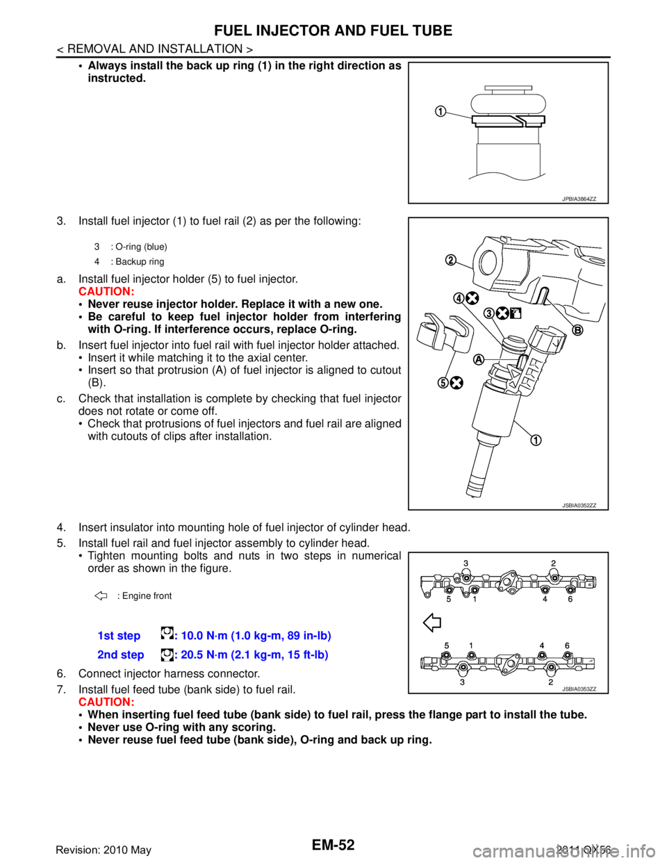
Always install the back up ring (1) in the right direction as
instructed.
3. Install fuel injector (1) to fuel rail (2) as per the following:
a. Install fuel injector holder (5) to fuel injector. CAUTION:
Never reuse injector holder. Replace it with a new one.
Be careful to keep fuel inject or holder from interfering
with O-ring. If interfer ence occurs, replace O-ring.
b. Insert fuel injector into fuel rail with fuel injector holder attached. Insert it while matching it to the axial center.
Insert so that protrusion (A) of fuel injector is aligned to cutout
(B).
c. Check that installation is complete by checking that fuel injector does not rotate or come off.
Check that protrusions of fuel in jectors and fuel rail are aligned
with cutouts of clips after installation.
4. Insert insulator into mounting hole of fuel injector of cylinder head.
5. Install fuel rail and fuel injector assembly to cylinder head. Tighten mounting bolts and nuts in two steps in numericalorder as shown in the figure.
6. Connect injector harness connector.
7. Install fuel feed tube (bank side) to fuel rail. CAUTION:
When inserting fuel feed tube (b ank side) to fuel rail, press the flange part to install the tube.
Never use O-ring with any scoring.
Never reuse fuel feed tube (ban k side), O-ring and back up ring.
JPBIA3864ZZ
3 : O-ring (blue)
4: Backup ring
JSBIA0352ZZ
: Engine front
1st step : 10.0 N·m (1.0 kg-m, 89 in-lb)
2nd step : 20.5 N·m (2.1 kg-m, 15 ft-lb)
JSBIA0353ZZ
Revision: 2010 May2011 QX56
Page 2654 of 5598
![INFINITI QX56 2011 Factory Service Manual
EM-92
< REMOVAL AND INSTALLATION >
CYLINDER HEAD
a. Apply new engine oil on new valve oil seal joint and seal lip.
b. Using the valve oil seal drift [SST: KV10115600 (J-38958)] (A),press fit valve se INFINITI QX56 2011 Factory Service Manual
EM-92
< REMOVAL AND INSTALLATION >
CYLINDER HEAD
a. Apply new engine oil on new valve oil seal joint and seal lip.
b. Using the valve oil seal drift [SST: KV10115600 (J-38958)] (A),press fit valve se](/manual-img/42/57033/w960_57033-2653.png)
EM-92
< REMOVAL AND INSTALLATION >
CYLINDER HEAD
a. Apply new engine oil on new valve oil seal joint and seal lip.
b. Using the valve oil seal drift [SST: KV10115600 (J-38958)] (A),press fit valve seal to height (b) shown in figure.
4. Install valve. NOTE:
Larger diameter valves are for intake side.
5. Install valve spring (with valve spring seat). Install narrow pitch (B) end [paint mark (C)] to cylinder headside (valve spring seat side).
6. Install valve spring retainer.
7. Install valve collet. Compress valve spring with the valve spring compressor [SST:
KV10116200 (J26336-A)] (A), the attachment [SST:
KV10115900 (J26336-20)] (C) and the adapter [SST:
KV10109220 ( — )] (B). Install valve collet with a magnet
hand.
CAUTION:
When working, take care not to damage valve lifter holes.
Tap valve stem edge lightly with plastic hammer after installa- tion to check its installed condition.
InspectionINFOID:0000000006289573
INSPECTION AFTER DISASSEMBLY
Cylinder Head Bolt s Outer Diameter
Cylinder head bolts are tightened by plastic zone tightening
method. Whenever the size difference between (B) and (A)
exceeds the limit, replace them with new one.
If reduction of outer diameter appears in a position other than (A),
use it as (A) point. Height (b)
Intake, Exhaust : 14.3 - 14.9 mm (0.563 - 0.587 in)
JPBIA1367ZZ
A : Wide pitch
: Cylinder head side
Paint mark color
Intake : Light green
Exhaust : Light blue
JPBIA0179ZZ
JPBIA1365ZZ
Limit [(B) - (A)] : 0.18 mm (0.0071 in)
c : 55 mm (2.17 in)
d : 12 mm (0.47 in)
JPBIA2144ZZ
Revision: 2010 May2011 QX56
Page 2655 of 5598
CYLINDER HEADEM-93
< REMOVAL AND INSTALLATION >
C
DE
F
G H
I
J
K L
M A
EM
NP
O
Cylinder Head Distortion
NOTE:
When performing this inspection, cylinder block distortion should be also checked. Refer to
EM-115, "
Inspec-
tion".
1. Using a scraper, wipe out oil, scale, gasket, s ealant and carbon deposits from surface of cylinder head.
CAUTION:
Never allow gasket fragments to enter engine oil or engine coolant passages.
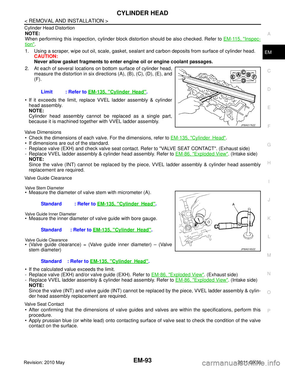
2. At each of several locations on bottom surface of cylinder head, measure the distortion in six directi ons (A), (B), (C), (D), (E), and
(F).
If it exceeds the limit, replace VVEL ladder assembly & cylinder head assembly.
NOTE:
Cylinder head assembly cannot be replaced as a single part,
because it is machined together with VVEL ladder assembly.
Valve Dimensions
Check the dimensions of each valv e. For the dimensions, refer to EM-135, "CylinderHead".
If dimensions are out of the standard.
- Replace valve (EXH) and check valve seat contact. Refer to "VALVE SEAT CONTACT". (Exhaust side)
- Replace VVEL ladder assembly & cylinder head assembly. Refer to EM-86, "
Exploded View". (Intake side)
NOTE:
Since the valve (INT) cannot be replaced by the pi ece, VVEL ladder assembly & cylinder head assembly
replacement are required.
Valve Guide Clearance
Valve Stem Diameter
Measure the diameter of valve stem with micrometer (A).
Valve Guide Inner Diameter
Measure the inner diameter of valve guide with bore gauge.
Valve Guide Clearance
(Valve guide clearance) = (Valve guide inner diameter) – (Valve
stem diameter)
If the calculated value exceeds the limit.
- Replace valve (EXH) and/or valve guide (EXH). Refer to EM-86, "
Exploded View". (Exhaust side)
- Replace VVEL ladder assembly & cylinder head assembly. Refer to EM-86, "
Exploded View". (Intake side)
NOTE:
Since the valve (INT) and valve guide (INT) cannot be repl aced by the piece, VVEL ladder assembly & cylin-
der head assembly replacement are required.
Valve Seat Contact
After confirming that the dimensions of valve guides and valves are within the specifications, perform this
procedure.
Apply prussian blue (or white lead) onto contacting surfac e of valve seat to check the condition of the valve
contact on the surface. Limit : Refer to
EM-135, "
CylinderHead".
JPBIA0176ZZ
Standard : Refer to EM-135, "CylinderHead".
Standard : Refer to EM-135, "
CylinderHead".
Standard : Refer to EM-135, "
CylinderHead".
JPBIA0183ZZ
Revision: 2010 May2011 QX56
Page 2699 of 5598
SERVICE DATA AND SPECIFICATIONS (SDS)
EM-137
< SERVICE DATA AND SPECIFICATIONS (SDS)
C
D E
F
G H
I
J
K L
M A
EM
NP
O
*1: Diameter made by intersection point of conic angles “
α1” and “ α2”
*
2: Diameter made by intersection point of conic angles “ α2” and “ α3”
*
3: Machining data
*
4: Parts settings are for exhaust side only
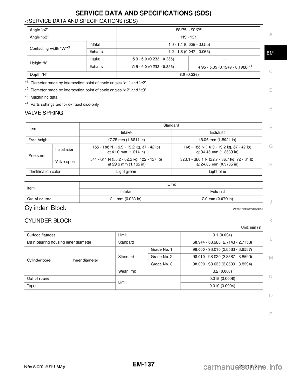
VALVE SPRING
Cylinder BlockINFOID:0000000006289595
CYLINDER BLOCK
Unit: mm (in)
Angle “ α2” 88°75 ′ - 90 °25 ′
Angle “ α3” 11 9 - 1 2 1°
Contacting width “W”*
3Intake 1.0 - 1.4 (0.039 - 0.055)
Exhaust 1.2 - 1.6 (0.047 - 0.063)
Height “h” Intake 5.9 - 6.0 (0.232 - 0.236) —
Exhaust 5.9 - 6.0 (0.232 - 0.236)
4.95 - 5.05 (0.1949 - 0.1988)*
4
Depth “H” 6.0 (0.236)
ItemStandard
Intake Exhaust
Free height 47.28 mm (1.8614 in) 48.06 mm (1.8921 in)
Pressure Installation
166 - 188 N (16.9 - 19.2 kg, 37 - 42 lb)
at 41.0 mm (1.614 in) 166 - 188 N (16.9 - 19.2 kg, 37 - 42 lb)
at 34.45 mm (1.3563 in)
Valve open 541 - 611 N (55.2 - 62.3 kg, 122 - 137 lb)
at 29.6 mm (1.165 in) 320.1 - 360.1 N (32.7 - 36.7 kg, 72 - 81 lb)
at 24.65 mm (0.9705 in)
Identification color Light green Light blue
Item Limit
Intake Exhaust
Out-of-square 2.1 mm (0.083 in) 2.0 mm (0.079 in)
Surface flatness Limit 0.1 (0.004)
Main bearing housing inner diameter Standard 68.944 - 68.968 (2.7143 - 2.7153)
Cylinder bore Inner diameter StandardGrade No. 1 98.000 - 98.010 (3.8583 - 3.8587)
Grade No. 2 98.010 - 98.020 (3.8587 - 3.8590)
Grade No. 3 98.020 - 98.030 (3.8590 - 3.8594)
Wear limit 0.2 (0.008)
Out-of-round Limit0.015 (0.0006)
Ta p e r 0.010 (0.0004)
Revision: 2010 May2011 QX56
Page 2703 of 5598
SERVICE DATA AND SPECIFICATIONS (SDS)
EM-141
< SERVICE DATA AND SPECIFICATIONS (SDS)
C
D E
F
G H
I
J
K L
M A
EM
NP
O
*: Total indicator reading
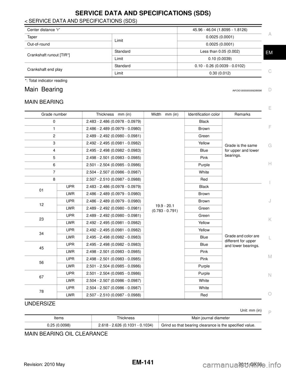
Main BearingINFOID:0000000006289596
MAIN BEARING
UNDERSIZE
Unit: mm (in)
MAIN BEARING OIL CLEARANCE
Center distance “r”
45.96 - 46.04 (1.8095 - 1.8126)
Ta p e r Limit 0.0025 (0.0001)
Out-of-round 0.0025 (0.0001)
Crankshaft runout [TIR*] Standard Less than 0.05 (0.002)
Limit 0.10 (0.0039)
Crankshaft end play Standard 0.10 - 0.26 (0.0039 - 0.0102)
Limit 0.30 (0.012)
Grade number Thickness mm (in) Width mm (in) Identification color Remarks
0 2.483 - 2.486 (0.0978 - 0.0979)
19.9 - 20.1
(0.783 - 0.791) Black
Grade is the same
for upper and lower
bearings.
1 2.486 - 2.489 (0.0979 - 0.0980) Brown
2 2.489 - 2.492 (0.0980 - 0.0981) Green
3 2.492 - 2.495 (0.0981 - 0.0982) Yellow
4 2.495 - 2.498 (0.0982 - 0.0983) Blue
5 2.498 - 2.501 (0.0983 - 0.0985) Pink
6 2.501 - 2.504 (0.0985 - 0.0986) Purple
7 2.504 - 2.507 (0.0986 - 0.0987) White
8 2.507 - 2.510 (0.0987 - 0.0988) Red
01 UPR 2.483 - 2.486 (0.0978 - 0.0979) Black
Grade and color are
different for upper
and lower bearings.
LWR 2.486 - 2.489 (0.0979 - 0.0980) Brown
12 UPR 2.486 - 2.489 (0.0979 - 0.0980) Brown
LWR 2.489 - 2.492 (0.0980 - 0.0981) Green
23 UPR 2.489 - 2.492 (0.0980 - 0.0981) Green
LWR 2.492 - 2.495 (0.0981 - 0.0982) Yellow
34 UPR 2.492 - 2.495 (0.0981 - 0.0982) Yellow
LWR 2.495 - 2.498 (0.0982 - 0.0983) Blue
45 UPR 2.495 - 2.498 (0.0982 - 0.0983) Blue
LWR 2.498 - 2.501 (0.0983 - 0.0985) Pink
56 UPR 2.498 - 2.501 (0.0983 - 0.0985) Pink
LWR 2.501 - 2.504 (0.0985 - 0.0986) Purple
67 UPR 2.501 - 2.504 (0.0985 - 0.0986) Purple
LWR 2.504 - 2.507 (0.0986 - 0.0987) White
78 UPR 2.504 - 2.507 (0.0986 - 0.0987) White
LWR 2.507 - 2.510 (0.0987 - 0.0988) Red
Items Thickness Main journal diameter
0.25 (0.0098) 2.618 - 2.626 (0.1031 - 0.1034) Grind so that bearing clearance is the specified value.
Revision: 2010 May2011 QX56
Page 2977 of 5598
HOW TO READ WIRING DIAGRAMSGI-13
< HOW TO USE THIS MANUAL >
C
DE
F
G H
I
J
K L
M B
GI
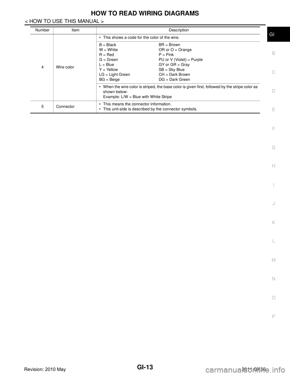
N
O P
4 Wire color This shows a code for the color of the wire.
B = Black
W = White
R = Red
G = Green
L = Blue
Y = Yellow
LG = Light Green
BG = Beige BR = Brown
OR or O = Orange
P = Pink
PU or V (Violet) = Purple
GY or GR = Gray
SB = Sky Blue
CH = Dark Brown
DG = Dark Green
When the wire color is striped, the base color is given first, followed by the stripe color as shown below:
Example: L/W = Blue with White Stripe
5 Connector This means the connector information.
This unit-side is described by the connector symbols.
Number Item Description
Revision: 2010 May2011 QX56
Page 2986 of 5598
GI-22
< HOW TO USE THIS MANUAL >
RECOMMENDED CHEMICAL PRODUCTS AND SEALANTS
RECOMMENDED CHEMICAL PRODUCTS AND SEALANTS
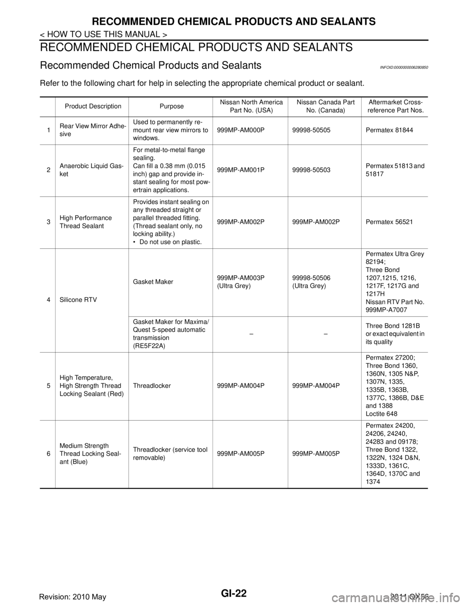
Recommended Chemical Products and SealantsINFOID:0000000006280850
Refer to the following chart for help in selecting the appropriate chemical product or sealant.
Product Description Purpose Nissan North America
Part No. (USA) Nissan Canada Part
No. (Canada) Aftermarket Cross-
reference Part Nos.
1 Rear View Mirror Adhe-
sive Used to permanently re-
mount rear view mirrors to
windows.
999MP-AM000P 99998-50505 Permatex 81844
2 Anaerobic Liquid Gas-
ket For metal-to-metal flange
sealing.
Can fill a 0.38 mm (0.015
inch) gap and provide in-
stant sealing for most pow-
ertrain applications.
999MP-AM001P 99998-50503
Permatex 51813 and
51817
3 High Performance
Thread Sealant Provides instant sealing on
any threaded straight or
parallel threaded fitting.
(Thread sealant only, no
locking ability.)
Do not use on plastic.
999MP-AM002P 999MP-AM002P Permatex 56521
4 Silicone RTV Gasket Maker
999MP-AM003P
(Ultra Grey)99998-50506
(Ultra Grey)Permatex Ultra Grey
82194;
Three Bond
1207,1215, 1216,
1217F, 1217G and
1217H
Nissan RTV Part No.
999MP-A7007
Gasket Maker for Maxima/
Quest 5-speed automatic
transmission
(RE5F22A) ––
Three Bond 1281B
or exact equivalent in
its quality
5 High Temperature,
High Strength Thread
Locking Sealant (Red)
Threadlocker 999MP-AM004P 999MP-AM004P Permatex 27200;
Three Bond 1360,
1360N, 1305 N&P,
1307N, 1335,
1335B, 1363B,
1377C, 1386B, D&E
and 1388
Loctite 648
6 Medium Strength
Thread Locking Seal-
ant (Blue) Threadlocker (service tool
removable)
999MP-AM005P 999MP-AM005P Permatex 24200,
24206, 24240,
24283 and 09178;
Three Bond 1322,
1322N, 1324 D&N,
1333D, 1361C,
1364D, 1370C and
1374
Revision: 2010 May2011 QX56