2011 INFINITI QX56 ignition
[x] Cancel search: ignitionPage 4543 of 5598
SE-84
< DTC/CIRCUIT DIAGNOSIS >
CLIMATE CONTROLLED SEATBACK BLOWER MOTOR
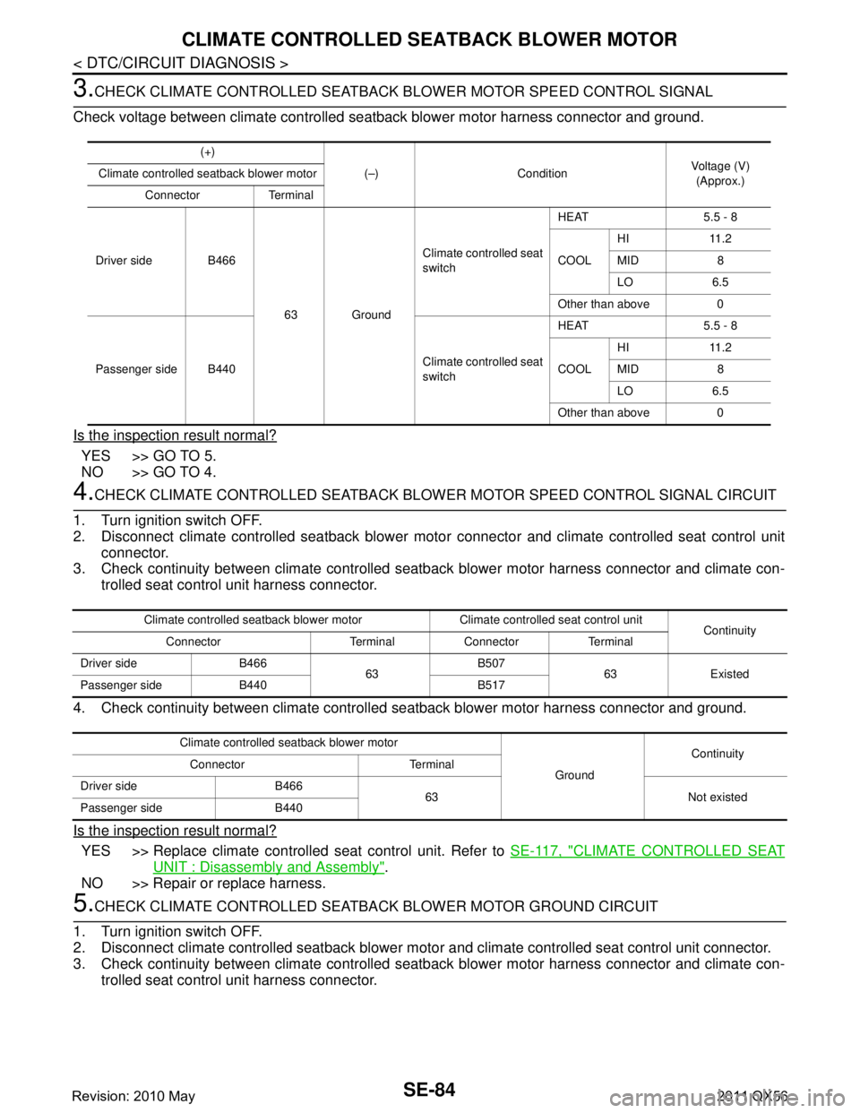
3.CHECK CLIMATE CONTROLLED SEATBACK BLOWER MOTOR SPEED CONTROL SIGNAL
Check voltage between climate controlled seat back blower motor harness connector and ground.
Is the inspection result normal?
YES >> GO TO 5.
NO >> GO TO 4.
4.CHECK CLIMATE CONTROLLED SEATBACK BLOWER MOTOR SPEED CONTROL SIGNAL CIRCUIT
1. Turn ignition switch OFF.
2. Disconnect climate controlled seatback blower moto r connector and climate controlled seat control unit
connector.
3. Check continuity between climate controlled seat back blower motor harness connector and climate con-
trolled seat control unit harness connector.
4. Check continuity between climate controlled seatback blower motor harness connector and ground.
Is the inspection result normal?
YES >> Replace climate controlled seat control unit. Refer to SE-117, "CLIMATE CONTROLLED SEAT
UNIT : Disassembly and Assembly".
NO >> Repair or replace harness.
5.CHECK CLIMATE CONTROLLED SEATBACK BLOWER MOTOR GROUND CIRCUIT
1. Turn ignition switch OFF.
2. Disconnect climate controlled seatback blower moto r and climate controlled seat control unit connector.
3. Check continuity between climate controlled seat back blower motor harness connector and climate con-
trolled seat control unit harness connector.
(+)
(–) Condition Voltage (V)
(Approx.)
Climate controlled seatback blower motor
Connector Terminal
Driver side B466 63 GroundClimate controlled seat
switch
HEAT 5.5 - 8
COOL
HI 11.2
MID 8
LO 6.5
Other than above 0
Passenger side B440 Climate controlled seat
switchHEAT 5.5 - 8
COOL
HI 11.2
MID 8
LO 6.5
Other than above 0
Climate controlled seatback blower motor Climate controlled seat control unit Continuity
Connector Terminal Connector Terminal
Driver side B466 63B507
63 Existed
Passenger side B440 B517
Climate controlled seatback blower motor
GroundContinuity
Connector Terminal
Driver side B466 63 Not existed
Passenger side B440
Revision: 2010 May2011 QX56
Page 4545 of 5598
SE-86
< DTC/CIRCUIT DIAGNOSIS >
CLIMATE CONTROLLED SEAT CUSHION BLOWER MOTOR
CLIMATE CONTROLLED SEAT CUSHION BLOWER MOTOR
Component Function CheckINFOID:0000000006217406
1.CHECK CLIMATE CONTROLLED SEAT CUSHION BLOWER MOTOR FUNCTION
When turning the climate controlled seat switch to the HEAT or COOL mode position, check that the climate
controlled seat cushion blower is operated in each specific mode.
Is the inspection result normal?
YES >> Climate controlled seat cushion blower motor is OK.
NO >> Refer to SE-86, "
Diagnosis Procedure".
Diagnosis ProcedureINFOID:0000000006217407
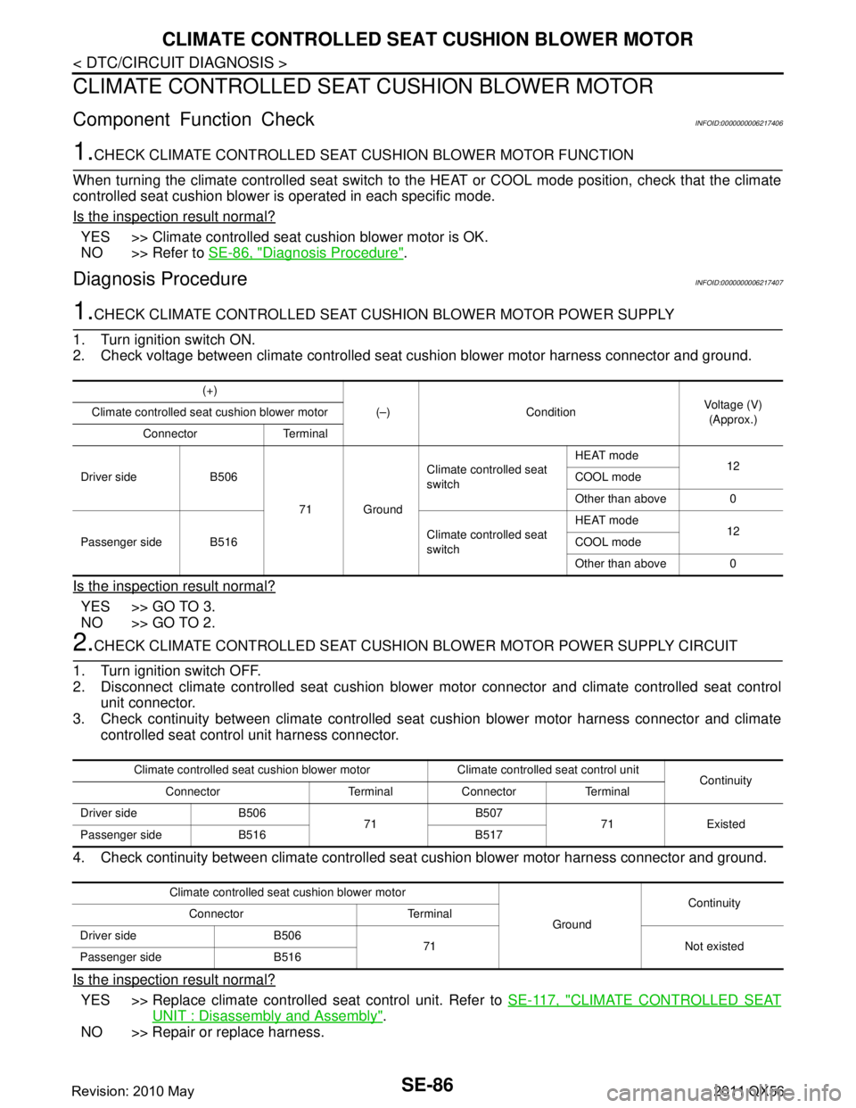
1.CHECK CLIMATE CONTROLLED SEAT CUSHION BLOWER MOTOR POWER SUPPLY
1. Turn ignition switch ON.
2. Check voltage between climate controlled seat cushion blower motor harness connector and ground.
Is the inspection result normal?
YES >> GO TO 3.
NO >> GO TO 2.
2.CHECK CLIMATE CONTROLLED SEAT CUSHION BLOWER MOTOR POWER SUPPLY CIRCUIT
1. Turn ignition switch OFF.
2. Disconnect climate controlled seat cushion blower motor connector and climate controlled seat control
unit connector.
3. Check continuity between climate controlled seat cushion blower motor harness connector and climate
controlled seat control unit harness connector.
4. Check continuity between climate controlled s eat cushion blower motor harness connector and ground.
Is the inspection result normal?
YES >> Replace climate controlled seat control unit. Refer to SE-117, "CLIMATE CONTROLLED SEAT
UNIT : Disassembly and Assembly".
NO >> Repair or replace harness.
(+)
(–) Condition Voltage (V)
(Approx.)
Climate controlled seat cushion blower motor
Connector Terminal
Driver side B506 71 GroundClimate controlled seat
switch
HEAT mode
12
COOL mode
Other than above 0
Passenger side B516 Climate controlled seat
switchHEAT mode
12
COOL mode
Other than above 0
Climate controlled seat cushion blower motor Climate controlled seat control unit Continuity
Connector Terminal Connector Terminal
Driver side B506 71B507
71 Existed
Passenger side B516 B517
Climate controlled seat cushion blower motor
GroundContinuity
Connector Terminal
Driver side B506 71 Not existed
Passenger side B516
Revision: 2010 May2011 QX56
Page 4546 of 5598
CLIMATE CONTROLLED SEAT CUSHION BLOWER MOTORSE-87
< DTC/CIRCUIT DIAGNOSIS >
C
DE
F
G H
I
K L
M A
B
SE
N
O P
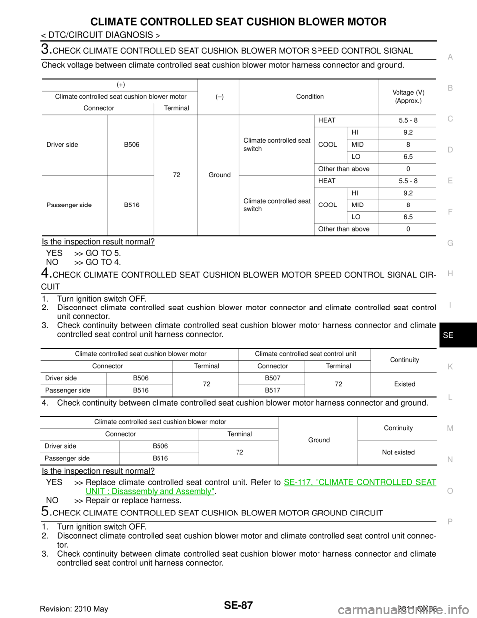
3.CHECK CLIMATE CONTROLLED SEAT CUSHION BLOWER MOTOR SPEED CONTROL SIGNAL
Check voltage between climate controlled seat cushion blower motor harness connector and ground.
Is the inspection result normal?
YES >> GO TO 5.
NO >> GO TO 4.
4.CHECK CLIMATE CONTROLLED SEAT CUSHION BL OWER MOTOR SPEED CONTROL SIGNAL CIR-
CUIT
1. Turn ignition switch OFF.
2. Disconnect climate controlled seat cushion blower motor connector and climate controlled seat control
unit connector.
3. Check continuity between climate controlled seat cushion blower motor harness connector and climate
controlled seat control unit harness connector.
4. Check continuity between climate controlled s eat cushion blower motor harness connector and ground.
Is the inspection result normal?
YES >> Replace climate controlled seat control unit. Refer to SE-117, "CLIMATE CONTROLLED SEAT
UNIT : Disassembly and Assembly".
NO >> Repair or replace harness.
5.CHECK CLIMATE CONTROLLED SEAT CUSHI ON BLOWER MOTOR GROUND CIRCUIT
1. Turn ignition switch OFF.
2. Disconnect climate controlled seat cushion blower motor and climate controlled seat control unit connec-
tor.
3. Check continuity between climate controlled seat cushion blower motor harness connector and climate
controlled seat control unit harness connector.
(+)
(–) Condition Voltage (V)
(Approx.)
Climate controlled seat cushion blower motor
Connector Terminal
Driver side B506 72 GroundClimate controlled seat
switch
HEAT 5.5 - 8
COOL
HI 9.2
MID 8
LO 6.5
Other than above 0
Passenger side B516 Climate controlled seat
switchHEAT 5.5 - 8
COOL
HI 9.2
MID 8
LO 6.5
Other than above 0
Climate controlled seat cushion blower motor Climate controlled seat control unit Continuity
Connector Terminal Connector Terminal
Driver side B506 72B507
72 Existed
Passenger side B516 B517
Climate controlled seat cushion blower motor
GroundContinuity
Connector Terminal
Driver side B506 72 Not existed
Passenger side B516
Revision: 2010 May2011 QX56
Page 4548 of 5598
CLIMATE CONTROLLED SEAT SWITCH INDICATORSE-89
< DTC/CIRCUIT DIAGNOSIS >
C
DE
F
G H
I
K L
M A
B
SE
N
O P
CLIMATE CONTROLLED SEAT SWITCH INDICATOR
Component Function CheckINFOID:0000000006217408
1.CHECK CLIMATE CONTROLLED SEA T SWITCH INDICATOR FUNCTION
Check that the related indicator lamp illuminates when c limate controlled seat switch is set to HEAT or COOL
mode.
Is the inspection result normal?
YES >> Climate controlled seat switch indicator function is OK.
NO >> Refer to SE-89, "
Diagnosis Procedure".
Diagnosis ProcedureINFOID:0000000006217409
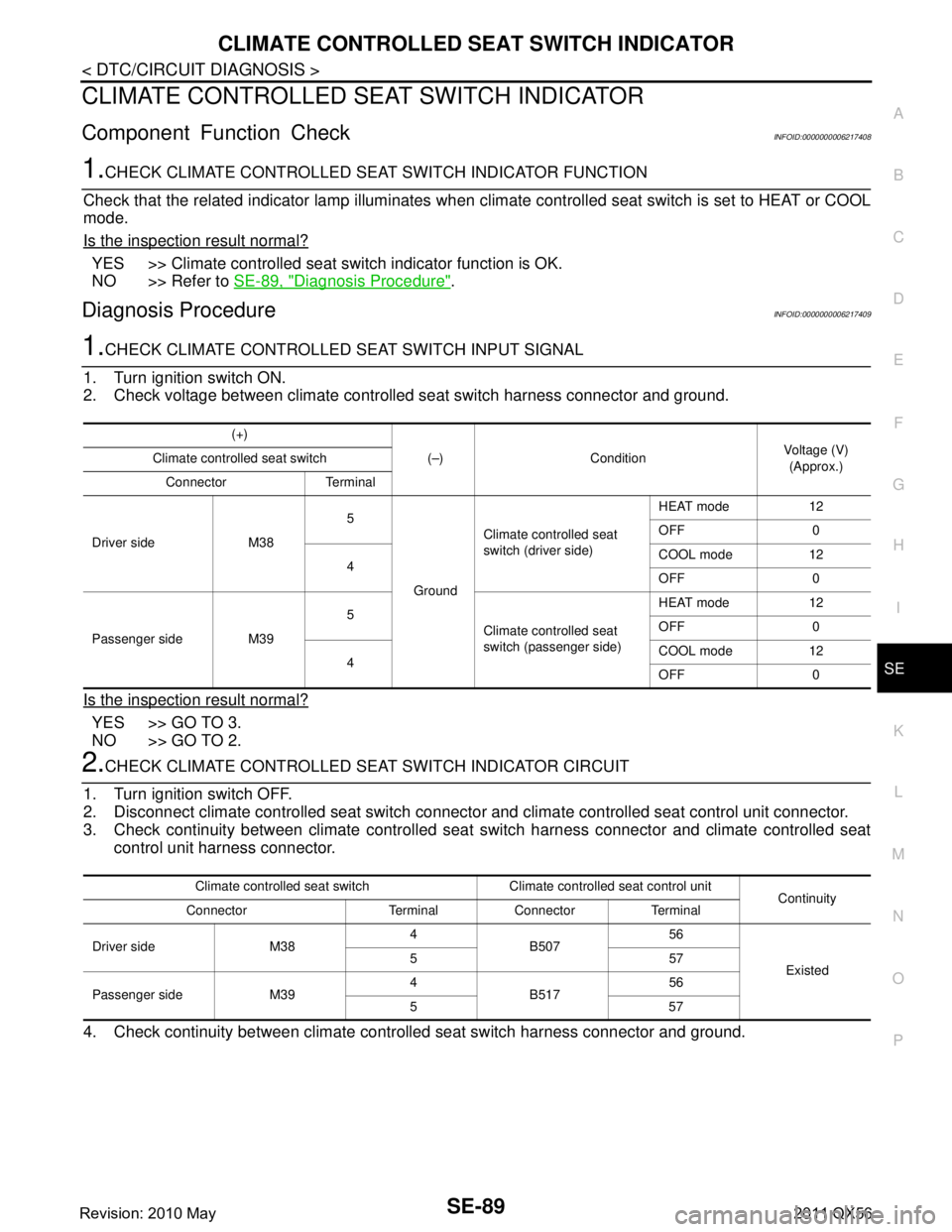
1.CHECK CLIMATE CONTROLLED SEAT SWITCH INPUT SIGNAL
1. Turn ignition switch ON.
2. Check voltage between climate controll ed seat switch harness connector and ground.
Is the inspection result normal?
YES >> GO TO 3.
NO >> GO TO 2.
2.CHECK CLIMATE CONTROLLED SEA T SWITCH INDICATOR CIRCUIT
1. Turn ignition switch OFF.
2. Disconnect climate controlled seat switch connecto r and climate controlled seat control unit connector.
3. Check continuity between climate controlled seat switch harness connector and climate controlled seat
control unit harness connector.
4. Check continuity between climate contro lled seat switch harness connector and ground.
(+)
(–) Condition Voltage (V)
(Approx.)
Climate controlled seat switch
Connector Terminal
Driver side M38 5
Ground Climate controlled seat
switch (driver side)
HEAT mode 12
OFF 0
4 COOL mode 12
OFF 0
Passenger side M39 5
Climate controlled seat
switch (passenger side) HEAT mode 12
OFF 0
4 COOL mode 12
OFF 0
Climate controlled seat switch Climate controlled seat control unit
Continuity
Connector Terminal Connector Terminal
Driver side M38 4
B507 56
Existed
557
Passenger side M39 4
B517 56
557
Revision: 2010 May2011 QX56
Page 4549 of 5598
SE-90
< DTC/CIRCUIT DIAGNOSIS >
CLIMATE CONTROLLED SEAT SWITCH INDICATOR
Is the inspection result normal?
YES >> Replace climate controlled seat control unit. Refer to SE-117, "CLIMATE CONTROLLED SEAT
UNIT : Disassembly and Assembly".
NO >> Repair or replace harness.
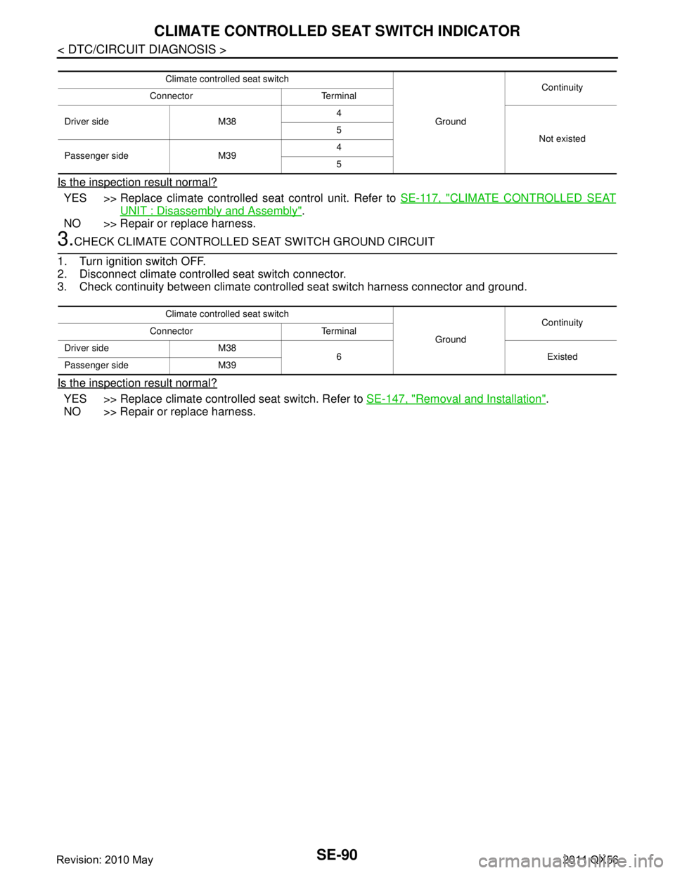
3.CHECK CLIMATE CONTROLLED SEAT SWITCH GROUND CIRCUIT
1. Turn ignition switch OFF.
2. Disconnect climate controlled seat switch connector.
3. Check continuity between climate contro lled seat switch harness connector and ground.
Is the inspection result normal?
YES >> Replace climate controlled seat switch. Refer to SE-147, "Removal and Installation".
NO >> Repair or replace harness.
Climate controlled seat switch
GroundContinuity
Connector Terminal
Driver side M38 4
Not existed
5
Passenger side M39 4
5
Climate controlled seat switch
GroundContinuity
Connector Terminal
Driver side M38 6 Existed
Passenger side M39
Revision: 2010 May2011 QX56
Page 4555 of 5598
SE-96
< SYMPTOM DIAGNOSIS >
CLIMATE CONTROLLED SEAT ACTIVATES ONCE BUT STOPS IMMEDIATELY
CLIMATE CONTROLLED SEAT ACTIVATES ONCE BUT STOPS IMMEDI-
ATELY
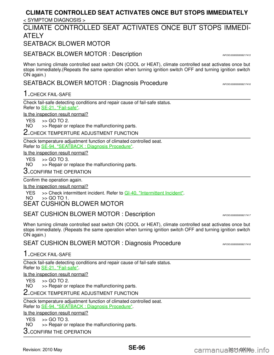
SEATBACK BLOWER MOTOR
SEATBACK BLOWER MOTOR : DescriptionINFOID:0000000006217415
When turning climate controlled seat switch ON (COOL or HEAT), climate controlled seat activates once but
stops immediately.(Repeats the same operation when turn ing ignition switch OFF and turning ignition switch
ON again.)
SEATBACK BLOWER MOTO R : Diagnosis ProcedureINFOID:0000000006217416
1.CHECK FAIL-SAFE
Check fail-safe detecting conditions and repair cause of fail-safe status.
Refer to SE-21, "
Fail-safe".
Is the inspection result normal?
YES >> GO TO 2.
NO >> Repair or replace the malfunctioning parts.
2.CHECK TEMPERTURE AD JUSTMENT FUNCTION
Check temperature adjustment func tion of climated controlled seat.
Refer to SE-94, "
SEATBACK : Diagnosis Procedure".
Is the inspection result normal?
YES >> GO TO 3.
NO >> Repair or replace the malfunctioning parts.
3.CONFIRM THE OPERATION
Confirm the operation again.
Is the inspection result normal?
YES >> Check intermittent incident. Refer to GI-40, "Intermittent Incident".
NO >> GO TO 1.
SEAT CUSHION BLOWER MOTOR
SEAT CUSHION BLOWER MOTOR : DescriptionINFOID:0000000006217417
When turning climate controlled seat switch ON (COOL or HEAT), climate controlled seat activates once but
stops immediately. (Repeats the same operation when turn ing ignition switch OFF and turning ignition switch
ON again.)
SEAT CUSHION BLOWER MO TOR : Diagnosis ProcedureINFOID:0000000006217418
1.CHECK FAIL-SAFE
Check fail-safe detecting conditions and repair cause of fail-safe status.
Refer to SE-21, "
Fail-safe".
Is the inspection result normal?
YES >> GO TO 2.
NO >> Repair or replace the malfunctioning parts.
2.CHECK TEMPERTURE AD JUSTMENT FUNCTION
Check temperature adjustment func tion of climated controlled seat.
Refer to SE-94, "
SEATBACK : Diagnosis Procedure".
Is the inspection result normal?
YES >> GO TO 3.
NO >> Repair or replace the malfunctioning parts.
3.CONFIRM THE OPERATION
Revision: 2010 May2011 QX56
Page 4572 of 5598
FRONT SEATSE-113
< REMOVAL AND INSTALLATION >
C
DE
F
G H
I
K L
M A
B
SE
N
O P
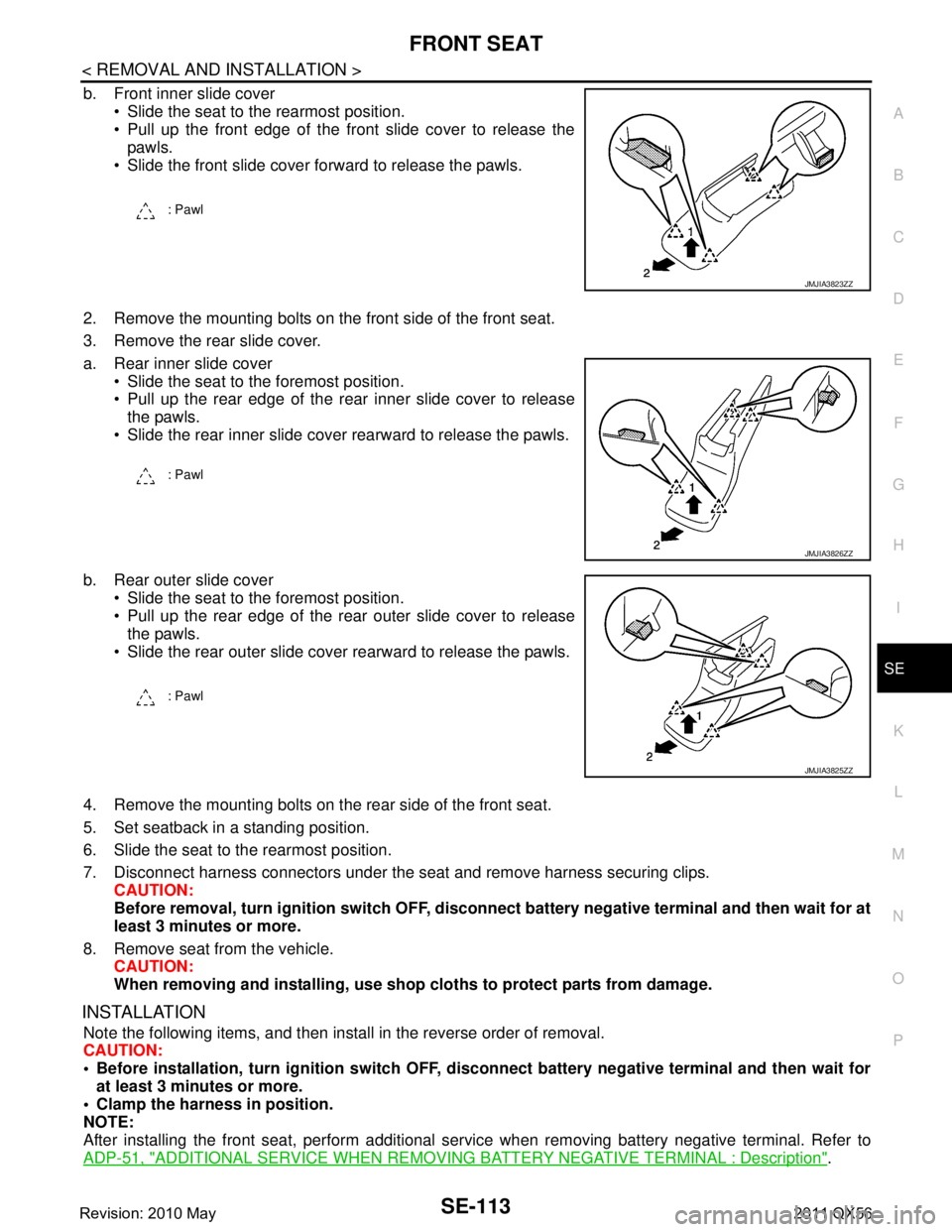
b. Front inner slide cover Slide the seat to the rearmost position.
Pull up the front edge of the front slide cover to release thepawls.
Slide the front slide cover forward to release the pawls.
2. Remove the mounting bolts on the front side of the front seat.
3. Remove the rear slide cover.
a. Rear inner slide cover Slide the seat to the foremost position.
Pull up the rear edge of the rear inner slide cover to releasethe pawls.
Slide the rear inner slide cover rearward to release the pawls.
b. Rear outer slide cover Slide the seat to the foremost position.
Pull up the rear edge of the rear outer slide cover to releasethe pawls.
Slide the rear outer slide cover rearward to release the pawls.
4. Remove the mounting bolts on t he rear side of the front seat.
5. Set seatback in a standing position.
6. Slide the seat to the rearmost position.
7. Disconnect harness connectors under the seat and remove harness securing clips. CAUTION:
Before removal, turn ignition sw itch OFF, disconnect battery negative terminal and then wait for at
least 3 minutes or more.
8. Remove seat from the vehicle. CAUTION:
When removing and installing, use shop cloths to protect parts from damage.
INSTALLATION
Note the following items, and then install in the reverse order of removal.
CAUTION:
Before installation, turn ignition switch OFF, disconnect battery ne gative terminal and then wait for
at least 3 minutes or more.
Clamp the harness in position.
NOTE:
After installing the front seat, perform additional serv ice when removing battery negative terminal. Refer to
ADP-51, "
ADDITIONAL SERVICE WHEN REMOVING BATTERY NEGATIVE TERMINAL : Description".
: Pawl
JMJIA3823ZZ
: Pawl
JMJIA3826ZZ
: Pawl
JMJIA3825ZZ
Revision: 2010 May2011 QX56
Page 4608 of 5598
SEC-1
BODY EXTERIOR, DOORS, ROOF & VEHICLE SECURITY
C
D
E
F
G H
I
J
L
M
SECTION SEC
A
B
SEC
N
O P
CONTENTS
SECURITY CONTROL SYSTEM
WITH INTELLIGE NT KEY SYSTEM
PRECAUTION ................ ...............................
5
PRECAUTIONS .............................................. .....5
Precaution for Supplemental Restraint System
(SRS) "AIR BAG" and "SEAT BELT PRE-TEN-
SIONER" ............................................................. ......
5
Precaution Necessary for Steering Wheel Rota-
tion after Battery Disconnect .....................................
5
Precaution for Procedure without Cowl Top Cover ......6
SYSTEM DESCRIPTION ..............................7
COMPONENT PARTS ................................... .....7
Component Parts Location .................................. ......7
Component Description .............................................8
A/T Shift Selector (Detention Switch) ........................8
BCM ..........................................................................8
ECM ..........................................................................9
IPDM E/R ..................................................................9
NATS Antenna Amp. .................................................9
TCM ..........................................................................9
Combination Meter ....................................................9
Door Switch ...............................................................9
Hood Switch ..............................................................9
Inside Key Antenna ...................................................9
Intelligent Key ............................................................9
Push-button Ignition Switch .....................................10
Remote Keyless Entry Receiver .............................10
Security Indicator Lamp ..........................................10
Starter Control Relay ...............................................10
Starter Relay ...........................................................10
Steering Lock Relay ................................................10
Steering Lock Unit ...................................................10
Stop Lamp Switch ...................................................10
Transmission Range Switch ....................................10
Vehicle Information Display .....................................11
SYSTEM .............................................................12
INTELLIGENT KEY SYSTEM/ENGINE START
FUNCTION ............................................................. ....
12
INTELLIGENT KEY SYSTEM/ENGINE START
FUNCTION : System Diagram ................................
12
INTELLIGENT KEY SYSTEM/ENGINE START
FUNCTION : System Description ............................
12
INFINITI VEHICLE IMMOBILIZER SYSTEM-NATS ....14
INFINITI VEHICLE IMMOBILIZER SYSTEM-
NATS : System Diagram .........................................
15
INFINITI VEHICLE IMMOBILIZER SYSTEM-
NATS : System Description .....................................
15
VEHICLE SECURITY SYSTEM .................................17
VEHICLE SECURITY SYSTEM : System Dia-
gram .................................................................... ....
17
VEHICLE SECURITY SYSTEM : System Descrip-
tion ...........................................................................
18
DIAGNOSIS SYSTEM (BCM) ...........................21
COMMON ITEM ..................................................... ....21
COMMON ITEM : CONSULT-III Function (BCM -
COMMON ITEM) .....................................................
21
INTELLIGENT KEY ................................................ ....22
INTELLIGENT KEY : CONSULT-III Function
(BCM - INTELLIGENT KEY) ....................................
22
THEFT ALM ........................................................... ....26
THEFT ALM : CONSULT-III Function (BCM -
THEFT) ................................................................ ....
26
IMMU ...................................................................... ....27
IMMU : CONSULT-III Function (BCM - IMMU) ........27
DIAGNOSIS SYSTEM (IPDM E/R) ...................28
CONSULT-III Function (IPDM E/R) .........................28
ECU DIAGNOSIS INFORMATION ..............30
ECM, IPDM E/R, BCM .......................................30
List of ECU Reference ......................................... ....30
Revision: 2010 May2011 QX56