Page 687 of 5598

BRM-12
< PREPARATION >
BODY COMPONENT PARTS
NOTE:
For the parts without a number described in the figure, it is supplied only with the assembly part that the part is included with.
Tensile strength column shows the largest strength value of a part in the component part. No. Parts name
Tensile strength
(MPa) Both sided anti-corrosive
precoated steel sections
1. Hood Under 440×
2. Front fender (RH & LH) Under 440 ×
3. Inner side roof rail (RH & LH) 590 —
4. Upper inner front pillar (RH & LH) c. T=1.6 mm
(0.063 in)
980
caution—
5. Inner center pillar (RH & LH) d. T=1.6 mm
(0.063 in)
980
caution×
6. Center sill reinforcement assembly (RH & LH) Under 440 ×
7. Side body assembly (RH & LH) Refer to No.8 −13
8. Upper front pillar reinforcement (RH & LH) 590 —
9. Lower center pillar brace (RH & LH) e. T=1.8 mm
(0.071 in)
980
caution—
10. Front pillar brace (RH & LH) 590 —
11. Outer sill reinforcement (RH & LH) 590 ×
12. Outer front side body (RH & LH) Under 440 ×
13. Front fender bracket assembly (RH & LH) Under 440 ×
14. Outer sill (RH & LH) Under 440 ×
15. Front door assembly (RH & LH) 440 ×
16. Outer front door panel (RH & LH) Under 440 ×
17. Rear door assembly (RH & LH) 440 ×
18. Outer rear door panel (RH & LH) Under 440 ×
19. Back pillar reinforcement (RH & LH) Under 440 —
20. Inner back pillar (RH & LH) Under 440 —
21. Inner rear side roof rail (RH & LH) Under 440 —
22. Inner rear pillar (RH & LH) 590 —
23. Lower inner rear pillar (RH & LH)v Under 440 —
24. Side panel reinforcement (RH & LH) Under 440 —
25. Outer rear wheelhouse (RH & LH) Under 440 ×
26. Inner rear wheelhouse (RH & LH) Under 440 ×
27. Outer rear wheelhouse extension (RH & LH) Under 440 ×
28. Roof assembly Under 440 —
29. Front roof rail 440 —
30. Roof bow No.3 Under 440 —
31. Roof bow No.4 Under 440 —
32. Roof bow No.5 Under 440 —
33. Rear roof rail 440 —
34. Rear fender (RH & LH) Under 440 ×
35. Back pillar assembly (RH & LH) Under 440 —
36. Rear fender bracket (RH & LH) Under 440 —
37. Fuel filler lid Under 440 ×
38. Rear fender extension (RH & LH) Under 440 ×
39. Back door Under 440 ×
Revision: 2010 May2011 QX56
Page 690 of 5598

CORROSION PROTECTIONBRM-15
< REMOVAL AND INSTALLATION >
C
DE
F
G H
I
J
L
M A
B
BRM
N
O P
REMOVAL AND INSTALLATION
CORROSION PROTECTION
DescriptionINFOID:0000000006248490
To provide improved corrosion prevention, the follo wing anti-corrosive measures have been implemented in
NISSAN production plants. When repairing or replacing body panels, it is necessary to use the same anti-cor-
rosive measures.
Anti-Corrosive Precoated Steel (Galvannealed Steel)
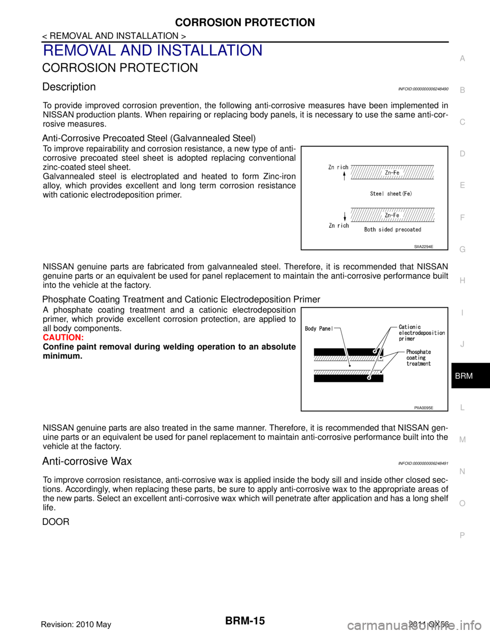
To improve repairability and corrosi on resistance, a new type of anti-
corrosive precoated steel sheet is adopted replacing conventional
zinc-coated steel sheet.
Galvannealed steel is electroplated and heated to form Zinc-iron
alloy, which provides excellent and long term corrosion resistance
with cationic electrodeposition primer.
NISSAN genuine parts are fabricated from galvannealed steel. Therefore, it is recommended that NISSAN
genuine parts or an equivalent be used for panel replacem ent to maintain the anti-corrosive performance built
into the vehicle at the factory.
Phosphate Coating Treatment and Cationic Electrodeposition Primer
A phosphate coating treatment and a cationic electrodeposition
primer, which provide excellent corrosion protection, are applied to
all body components.
CAUTION:
Confine paint removal during we lding operation to an absolute
minimum.
NISSAN genuine parts are also treated in the same manner. Therefore, it is recommended that NISSAN gen-
uine parts or an equivalent be used for panel replacement to maintain anti-corrosive performance built into the
vehicle at the factory.
Anti-corrosive WaxINFOID:0000000006248491
To improve corrosion resistance, anti-corrosive wax is applied inside the body sill and inside other closed sec-
tions. Accordingly, when replacing these parts, be sure to apply anti-corrosive wax to the appropriate areas of
the new parts. Select an excellent anti-corrosive wax which will penetrate after application and has a long shelf
life.
DOOR
SIIA2294E
PIIA0095E
Revision: 2010 May2011 QX56
Page 692 of 5598
CORROSION PROTECTIONBRM-17
< REMOVAL AND INSTALLATION >
C
DE
F
G H
I
J
L
M A
B
BRM
N
O P
Stone Guard CoatINFOID:0000000006248493
To prevent damage caused by stones, the lower outer body panel (fender, door, etc.) have an additional layer
of Stone Guard Coating over the ED primer coating. When replacing or repairing these panels, apply Stone
Guard coating to the same portions as before. Use a c oating which is rust preventive, durable, shock-resistant
and has a long shelf life.
: Undercoated areas
: Sealed portions
JSKIA2037ZZ
Revision: 2010 May2011 QX56
Page 731 of 5598
BRM-56
< SERVICE DATA AND SPECIFICATIONS (SDS)
BODY ALIGNMENT
Unit: mm (in)
Rear BodyINFOID:0000000006248512
Measurement
Dimensions marked with ″*″ indicate symmetrically identical dimensions on both the right and left hand of the
vehicle.
Measurement Points
: Vehicle front
Point Material Point Material
A Cowl top positioning mark of center positioning
mark H, h, J, j, K, k,
M, m
Center pillar indent
B, b Roof indent O, o, P, p Rear fender indent
C, c Front pillar joggle Q, q Parking brake bracket hole center φ13 (0.51)
D, d, E, e, N, n Outer side body indent R, r 2nd seat mounting front crossmember hole cen-
ter
φ7 (0.28)
F, f, G, g Front pillar indent S, s, T, t, U, u,
V, vDoor hinge installing hole center
S, s, U, u:
φ9 (0.35)
T, t, V, v: φ12 (0.47)
Unit: mm (in)
JSKIA1902GB
Revision: 2010 May2011 QX56
Page 734 of 5598

LOCATION OF PLASTIC PARTSBRM-59
< SERVICE DATA AND SPECIFICATIONS (SDS)
C
DE
F
G H
I
J
L
M A
B
BRM
N
O P
Location of Plastic PartsINFOID:0000000006248514
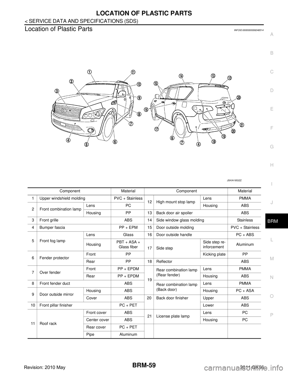
Component Material Component Material
1 Upper windshield molding PVC + Stainless 12 High mount stop lampLens PMMA
2 Front combination lamp Lens PC Housing ABS
Housing PP 13 Back door air spoiler ABS
3 Front grille ABS 14 Side window glass molding Stainless
4 Bumper fascia PP + EPM 15 Door outside molding PVC + Stainless
5 Front fog lamp Lens Glass 16 Door outside handle PC + ABS
Housing
PBT + ASA +
Glass fiber 17 Side step Side step re-
inforcement
Aluminum
6 Fender protector Front PP Kicking plate PP
Rear PP 18 Reflector ABS
7 Over fender Front PP + EPDM
19Rear combination lamp
(Rear fender)
Lens PMMA
Rear PP + EPDM Housing ABS
8 Front fender duct ABS Rear combination lamp
(Back door)Lens PMMA
9 Door outside mirror Housing ABS Housing PC + ASA
Cover ABS 20 Back door finisher Upper ABS
10 Front pillar finisher PC + PET Lower ABS
11 R o o f r a c k Front cover ABS
21 License plate lampLens PC
Center cover ABS Housing PC
Rear cover PC + PET
Pipe Aluminum
JSKIA1953ZZ
Revision: 2010 May2011 QX56
Page 1236 of 5598
DAS
WARNING SYSTEMS SWITCHDAS-271
< REMOVAL AND INSTALLATION > [FCW]
C
D
E
F
G H
I
J
K L
M B
N P A
REMOVAL AND INSTALLATION
WARNING SYSTEMS SWITCH
Removal and InstallationINFOID:0000000006223696
REMOVAL
1. Remove the instrument lower panel (LH). Refer to IP-14, "Removal and Installation".
2. Remove warning systems switch from instrument driver lower panel.
NOTE:
Warning systems switch and automatic back door switch are integrated.
INSTALLATION
Install in the reverse order of removal.
Revision: 2010 May2011 QX56
Page 1307 of 5598
![INFINITI QX56 2011 Factory Service Manual
DAS-342
< BASIC INSPECTION >[LDW & LDP]
CAMERA AIMING ADJUSTMENT
3. Mark point “E” on the line “LH” at the
positions 3850 mm (151.57 in) from point “A”.
4. Draw line “RH” passing thr INFINITI QX56 2011 Factory Service Manual
DAS-342
< BASIC INSPECTION >[LDW & LDP]
CAMERA AIMING ADJUSTMENT
3. Mark point “E” on the line “LH” at the
positions 3850 mm (151.57 in) from point “A”.
4. Draw line “RH” passing thr](/manual-img/42/57033/w960_57033-1306.png)
DAS-342
< BASIC INSPECTION >[LDW & LDP]
CAMERA AIMING ADJUSTMENT
3. Mark point “E” on the line “LH” at the
positions 3850 mm (151.57 in) from point “A”.
4. Draw line “RH” passing through points “C” and “D” on the right side of vehicle in the same way as step 2. NOTE:
Approximately 4 m (13.12 ft) or more from the front end of vehicle.
5. Mark point “F” on the line “RH” at the positions 3850 mm (151.57 in) from point “C”.
6. Draw line “FW” passing through the points “E” and “F” on the front side of vehicle.
7. Mark point “X” at the center of point “E” and “F” on the line “FW”.
CAUTION:
Make sure that “E” to “X” is equal to “F” to “X”.
8. Position the center of the ri ght target to point of “X”.
>> Go to DAS-342, "
Work Procedure (Camera Aiming
Adjustment)".
Work Procedure (Camera Aiming Adjustment)INFOID:0000000006223737
CAUTION:
Perform the adjustment under unloaded vehicle condition.
1.CHECK VEHICLE HEIGHT
Measure the wheelarch height. Calculate “Dh”.
NOTE:
“Dh” may be calculated as a minus value.
>> GO TO 2.
2.CAMERA AIMING ADJUSTMENT
CAUTION:
Operate CONSULT-III outside the vehic le, and close all the doors. (To retain vehicle attitude appropri-
ately)
1. Select “Work Support” on “L ANE CAMERA” with CONSULT-III.
2. Select “AUTO AIM”.
3. Confirm the following items;
- The target should be accurately placed.
- The vehicle should be stopped.
4. Select “Start” to perform camera aiming. CAUTION:
Never select “Start” when the target is not accurately placed.
Wait 5 seconds or more after selecting “Start”.
5. Input “Dh”, and then select “Start”.
CAUTION:
Never change “Ht” and “Dt”.
6. Confirm the displayed item.
- “Normally Completed”: Select “Completion”.
- “SUSPENSION”, “X AIMING NG Y”, “ABNORMALL Y COMPLETED”: Perform the following services.
JPOIA0173GB
Dh [mm] = (Hfl + Hfr) ÷ 2 − 903
where, Hfl: Front left wheelarch height [mm]
Hfr: Front right wh eelarch height [mm]
JSOIA0361ZZ
Revision: 2010 May2011 QX56
Page 1369 of 5598
DAS-404
< REMOVAL AND INSTALLATION >[LDW & LDP]
WARNING SYSTEMS SWITCH
WARNING SYSTEMS SWITCH
Removal and InstallationINFOID:0000000006223844
REMOVAL
1. Remove the instrument lower panel (LH). Refer to
IP-14, "Removal and Installation".
2. Remove warning systems switch from instrument driver lower panel.
NOTE:
Warning systems switch and automatic back door switch are integrated.
INSTALLATION
Install in the reverse order of removal.
Revision: 2010 May2011 QX56