2011 INFINITI QX56 ESP
[x] Cancel search: ESPPage 3904 of 5598
![INFINITI QX56 2011 Factory Service Manual
PCS
B2618 BCMPCS-63
< DTC/CIRCUIT DIAGNOSIS > [POWER DISTRIBUTION SYSTEM]
C
D
E
F
G H
I
J
K L
B A
O P
N
B2618 BCM
DTC LogicINFOID:0000000006220212
DTC DETECTION LOGIC
NOTE:
If DTC B2618 is displaye INFINITI QX56 2011 Factory Service Manual
PCS
B2618 BCMPCS-63
< DTC/CIRCUIT DIAGNOSIS > [POWER DISTRIBUTION SYSTEM]
C
D
E
F
G H
I
J
K L
B A
O P
N
B2618 BCM
DTC LogicINFOID:0000000006220212
DTC DETECTION LOGIC
NOTE:
If DTC B2618 is displaye](/manual-img/42/57033/w960_57033-3903.png)
PCS
B2618 BCMPCS-63
< DTC/CIRCUIT DIAGNOSIS > [POWER DISTRIBUTION SYSTEM]
C
D
E
F
G H
I
J
K L
B A
O P
N
B2618 BCM
DTC LogicINFOID:0000000006220212
DTC DETECTION LOGIC
NOTE:
If DTC B2618 is displayed with DTC U1000, first per
form the trouble diagnosis for DTC U1000. Refer to
BCS-70, "
DTC Logic".
If DTC B2618 is displayed with DTC U1010, first per form the trouble diagnosis for DTC U1010. Refer to
BCS-71, "
DTC Logic".
DTC CONFIRMATION PROCEDURE
1.PERFORM DTC CONFIRMATION PROCEDURE
1. Turn ignition switch ON under the following conditions, and wait for 1 second or more.
- Selector lever is in the P or N position
- Do not depress brake pedal
2. Check “Self-diagnosis result” of BCM with CONSULT-III.
Is DTC detected?
YES >> Go to PCS-63, "Diagnosis Procedure".
NO >> INSPECTION END
Diagnosis ProcedureINFOID:0000000006220213
1.INSPECTION START
1. Turn ignition switch ON.
2. Select “Self-diagnosis resu lt” of BCM with CONSULT-III.
3. Touch “ERASE”.
4. Perform DTC Confirmation Procedure. See PCS-63, "
DTC Logic".
Is the 1st trip DTC B2618 displayed again?
YES >> Replace BCM. Refer to BCS-81, "Removal and Installation"
NO >> INSPECTION END
DTC No.Trouble diagnosis
name DTC detecting condition Possible cause
B2618 BCM An immediate operation of ignition relay (IPDM E/R) is re-
quested by BCM, but there is no response for more than
1 second BCM
Revision: 2010 May2011 QX56
Page 3924 of 5598

PG
COMPONENT PARTSPG-5
< SYSTEM DESCRIPTION >
C
DE
F
G H
I
J
K L
B A
O P
N
SYSTEM DESCRIPTION
COMPONENT PARTS
Circuit BreakerINFOID:0000000006275745
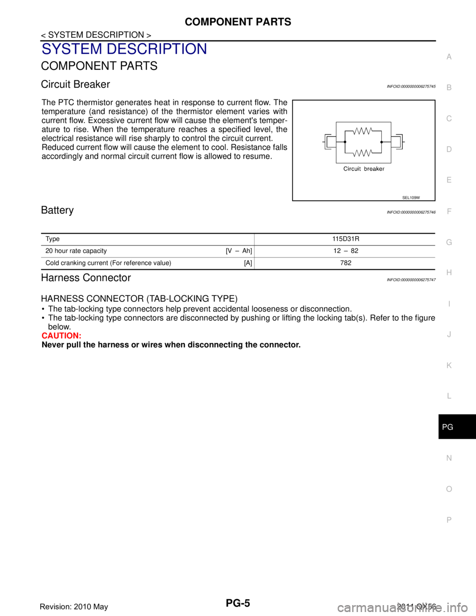
The PTC thermistor generates heat in response to current flow. The
temperature (and resistance) of t
he thermistor element varies with
current flow. Excessive current flow will cause the element's temper-
ature to rise. When the temperature reaches a specified level, the
electrical resistance will rise shar ply to control the circuit current.
Reduced current flow will cause the element to cool. Resistance falls
accordingly and normal circuit current flow is allowed to resume.
BatteryINFOID:0000000006275746
Harness ConnectorINFOID:0000000006275747
HARNESS CONNECTOR (TAB-LOCKING TYPE)
The tab-locking type connectors help prevent accidental looseness or disconnection.
The tab-locking type connectors are disconnected by pushi ng or lifting the locking tab(s). Refer to the figure
below.
CAUTION:
Never pull the harness or wires when disconnecting the connector.
SEL109W
Ty pe 115D31R
20 hour rate capacity [V – Ah] 12 – 82
Cold cranking current (For reference value) [A] 782
Revision: 2010 May2011 QX56
Page 3925 of 5598
![INFINITI QX56 2011 Factory Service Manual
PG-6
< SYSTEM DESCRIPTION >
COMPONENT PARTS
[Example]
HARNESS CONNECTOR (SLIDE-LOCKING TYPE)
A new style slide-locking type connector is used on certain systems and components, especially those
rel INFINITI QX56 2011 Factory Service Manual
PG-6
< SYSTEM DESCRIPTION >
COMPONENT PARTS
[Example]
HARNESS CONNECTOR (SLIDE-LOCKING TYPE)
A new style slide-locking type connector is used on certain systems and components, especially those
rel](/manual-img/42/57033/w960_57033-3924.png)
PG-6
< SYSTEM DESCRIPTION >
COMPONENT PARTS
[Example]
HARNESS CONNECTOR (SLIDE-LOCKING TYPE)
A new style slide-locking type connector is used on certain systems and components, especially those
related to OBD.
The slide-locking type connectors help prevent incomplete locking and accidental looseness or disconnec-
tion.
The slide-locking type connectors are disconnected by pushing or pulling the slider. Refer to the figure below.
CAUTION:
Never pull the harness or wires when disconnecting the connector.
Be careful not to damage the connector su pport bracket when disconnecting the connector.
SEL769DA
Revision: 2010 May2011 QX56
Page 4093 of 5598

PWC-8
< SYSTEM DESCRIPTION >
SYSTEM
SYSTEM
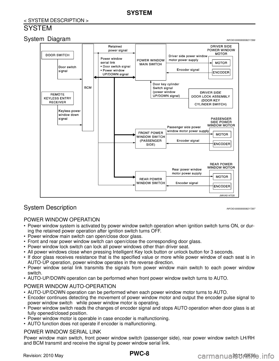
System DiagramINFOID:0000000006217266
System DescriptionINFOID:0000000006217267
POWER WINDOW OPERATION
Power window system is activated by power window switch operation when ignition switch turns ON, or dur-
ing the retained power operation after ignition switch turns OFF.
Power window main switch can open/close door glass.
Front and rear power window switch can open/close the corresponding door glass.
Power window lock switch can lock all power windows other than driver seat.
All power windows close when pressing Intelligent Ke y lock button or unlock button for 3 seconds.
If door glass receives resistance that is the specifi ed value or more while power window of each seat is in
AUTO-UP operation, power window operates in the reverse direction.
Power window serial link transmits the signals from power window main switch to each power window switch.
AUTO-UP/DOWN operation can be performed when front power window switch turns to AUTO.
POWER WINDOW AUTO-OPERATION
AUTO-UP/DOWN operation can be performed when each power window motor turns to AUTO.
Encoder continues detecting the movement of power window motor and output the encoder pulse signal to
power window switch while power window motor is operating.
Power window switch reads the changes of encoder signal and stops AUTO operation when door glass is at
fully opened/closed position.
Power window motor is operable in case encoder is malfunctioning.
AUTO function does not operate if encoder is malfunctioning.
POWER WINDOW SERIAL LINK
Power window main switch, front power window switch (passenger side), rear power window switch LH/RH
and BCM transmit and receive the signal by power window serial link.
JMKIA5147GB
Revision: 2010 May2011 QX56
Page 4240 of 5598

RF-26
< SYMPTOM DIAGNOSIS >
SQUEAK AND RATTLE TROUBLE DIAGNOSES
SQUEAK AND RATTLE TROUBLE DIAGNOSES
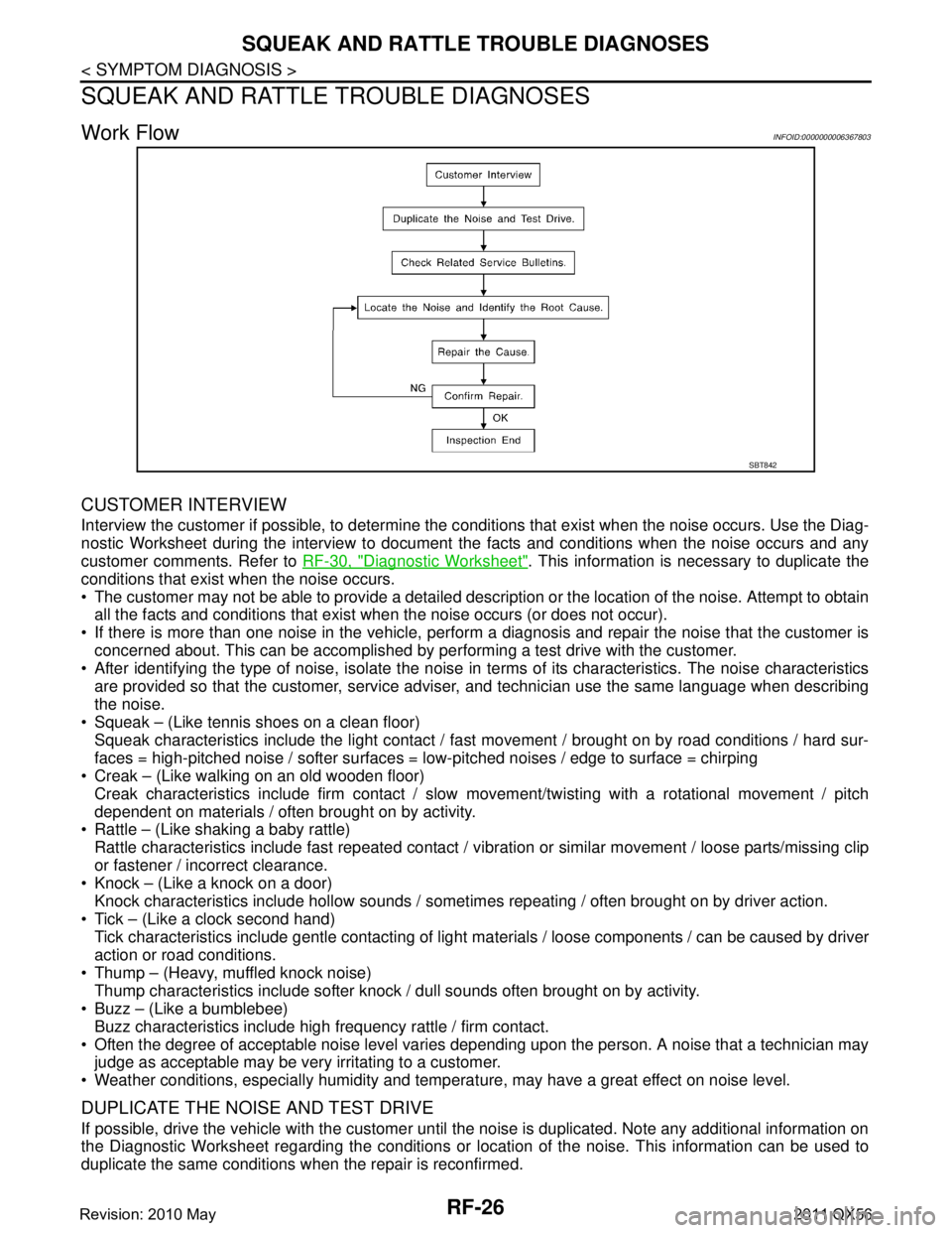
Work FlowINFOID:0000000006367803
CUSTOMER INTERVIEW
Interview the customer if possible, to determine the c onditions that exist when the noise occurs. Use the Diag-
nostic Worksheet during the interview to document the facts and conditions when the noise occurs and any
customer comments. Refer to RF-30, "
Diagnostic Worksheet". This information is necessary to duplicate the
conditions that exist when the noise occurs.
The customer may not be able to provide a detailed description or the location of the noise. Attempt to obtain all the facts and conditions that exist w hen the noise occurs (or does not occur).
If there is more than one noise in the vehicle, perform a diagnosis and repair the noise that the customer is
concerned about. This can be accomplished by per forming a test drive with the customer.
After identifying the type of noise, isolate the noise in terms of its characteristics. The noise characteristics
are provided so that the customer, service advis er, and technician use the same language when describing
the noise.
Squeak – (Like tennis shoes on a clean floor)
Squeak characteristics include the light contact / fast movement / brought on by road conditions / hard sur-
faces = high-pitched noise / softer surfaces = low-pitched noises / edge to surface = chirping
Creak – (Like walking on an old wooden floor)
Creak characteristics include firm contact / slow movement/twisting with a rotational movement / pitch
dependent on materials / often brought on by activity.
Rattle – (Like shaking a baby rattle)
Rattle characteristics include fast repeated contact / vibr ation or similar movement / loose parts/missing clip
or fastener / incorrect clearance.
Knock – (Like a knock on a door)
Knock characteristics include hollow sounds / someti mes repeating / often brought on by driver action.
Tick – (Like a clock second hand) Tick characteristics include gentle contacting of light materials / loose components / can be caused by driver
action or road conditions.
Thump – (Heavy, muffled knock noise) Thump characteristics include softer knock / dull sounds often brought on by activity.
Buzz – (Like a bumblebee)
Buzz characteristics include high frequency rattle / firm contact.
Often the degree of acceptable noise level varies depending upon the person. A noise that a technician may
judge as acceptable may be very irritating to a customer.
Weather conditions, especially humidity and temperat ure, may have a great effect on noise level.
DUPLICATE THE NOISE AND TEST DRIVE
If possible, drive the vehicle with the customer until the noise is duplicated. Note any additional information on
the Diagnostic Worksheet regarding the conditions or lo cation of the noise. This information can be used to
duplicate the same conditions when the repair is reconfirmed.
SBT842
Revision: 2010 May2011 QX56
Page 4308 of 5598

DIAGNOSIS SYSTEM (PRE-CRASH SEAT BELT)SBC-11
< SYSTEM DESCRIPTION >
C
DE
F
G
I
J
K L
M A
B
SBC
N
O P
DIAGNOSIS SYSTEM (P RE-CRASH SEAT BELT)
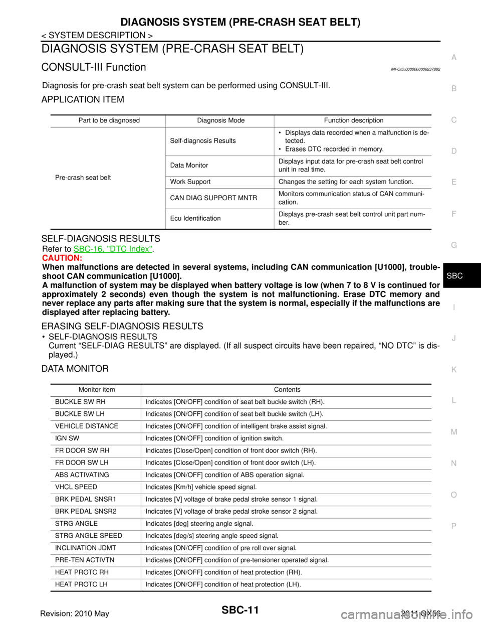
CONSULT-III FunctionINFOID:0000000006237882
Diagnosis for pre-crash seat belt syst em can be performed using CONSULT-III.
APPLICATION ITEM
SELF-DIAGNOSIS RESULTS
Refer to SBC-16, "DTC Index".
CAUTION:
When malfunctions are detect ed in several systems, includin g CAN communication [U1000], trouble-
shoot CAN communication [U1000].
A malfunction of system may be disp layed when battery voltage is low (when 7 to 8 V is continued for
approximately 2 seconds) even though the system is not malfunctioning. Erase DTC memory and
never replace any parts after making sure that the syst em is normal, especially if the malfunctions are
displayed after replacing battery.
ERASING SELF-DIAGNOSIS RESULTS
SELF-DIAGNOSIS RESULTS Current “SELF-DIAG RESULTS” are displayed. (If all suspect circuits have been repaired, “NO DTC” is dis-
played.)
DATA MONITOR
Part to be diagnosed Diagnosis Mode Function description
Pre-crash seat belt Self-diagnosis Results
Displays data recorded when a malfunction is de-
tected.
Erases DTC recorded in memory.
Data Monitor Displays input data for pre-crash seat belt control
unit in real time.
Work Support Changes the setting for each system function.
CAN DIAG SUPPORT MNTR Monitors communication status of CAN communi-
cation.
Ecu Identification Displays pre-crash seat belt control unit part num-
ber.
Monitor item Contents
BUCKLE SW RH Indicates [ON/OFF] condition of seat belt buckle switch (RH).
BUCKLE SW LH Indicates [ON/OFF] condition of seat belt buckle switch (LH).
VEHICLE DISTANCE Indicates [ON/OFF] condit ion of intelligent brake assist signal.
IGN SW Indicates [ON/OFF] condition of ignition switch.
FR DOOR SW RH Indicates [Close/Open] condition of front door switch (RH).
FR DOOR SW LH Indicates [Close/Open] condition of front door switch (LH).
ABS ACTIVATING Indicates [ON/OFF] co ndition of ABS operation signal.
VHCL SPEED Indicates [Km/h] vehicle speed signal.
BRK PEDAL SNSR1 Indicates [V] voltage of brake pedal stroke sensor 1 signal.
BRK PEDAL SNSR2 Indicates [V] voltage of brake pedal stroke sensor 2 signal.
STRG ANGLE Indicates [deg] steering angle signal.
STRG ANGLE SPEED Indicates [deg/s] steering angle speed signal.
INCLINATION JDMT Indicates [ON/OFF] condition of pre roll over signal.
PRE-TEN ACTIVTN Indicates [ON/OFF] condition of pre-tensioner operated signal.
HEAT PROTC RH Indicates [ON/OFF] condition of heat protection (RH).
HEAT PROTC LH Indicates [ON/OFF] condition of heat protection (LH).
Revision: 2010 May2011 QX56
Page 4369 of 5598
![INFINITI QX56 2011 Factory Service Manual
STRUCTURE AND OPERATIONSCS-9
< SYSTEM DESCRIPTION > [HBMC]
C
D
F
G H
I
J
K L
M A
B
SCS
N
O P
STRUCTURE AND OPERATION
Hydraulic Body-Moti on Control SystemINFOID:0000000006256001
Shock AbsorberINFOID: INFINITI QX56 2011 Factory Service Manual
STRUCTURE AND OPERATIONSCS-9
< SYSTEM DESCRIPTION > [HBMC]
C
D
F
G H
I
J
K L
M A
B
SCS
N
O P
STRUCTURE AND OPERATION
Hydraulic Body-Moti on Control SystemINFOID:0000000006256001
Shock AbsorberINFOID:](/manual-img/42/57033/w960_57033-4368.png)
STRUCTURE AND OPERATIONSCS-9
< SYSTEM DESCRIPTION > [HBMC]
C
D
F
G H
I
J
K L
M A
B
SCS
N
O P
STRUCTURE AND OPERATION
Hydraulic Body-Moti on Control SystemINFOID:0000000006256001
Shock AbsorberINFOID:0000000006256002
The use of accumulator-generated pressure responsive to driving conditions or pressure generated by oil flow
to the upper/lower chamber improves the steering stabili ty at curving, in addition to the running performance
and a ride quality during off-road travel.
FRONT SIDE
Oil enters from oil inlet outlet hole (A) and flows into lower chamber (3) via outside oil path of cylinder inside.
Oil enters from oil inlet outlet hole (B) and flows into upper chamber (1). With the pressure difference between
oil flowed into the upper chamber and lower chamber, the piston (2) moves up and down and conveys a force
generated through this motion to the tires.
1. Middle tube assembly RH 2. Accumulator assembly RH 3. Front tube assembly A
4. Front tube assembly B 5. Accumulator assembly LH 6. PPMU pipe A
7. PPMU assembly 8. Middle tube assembly LH 9. PPMU pipe B
10. Rear tube assembly A 11. Rear tube assembly B
:Vehicle front
JSEIA0228ZZ
Revision: 2010 May2011 QX56
Page 4437 of 5598
![INFINITI QX56 2011 Factory Service Manual
C1804 VHCL HEIGHT ADJ UPSCS-77
< DTC/CIRCUIT DIAGNOSIS > [AIR LEVELIZER CONTROL SYSTEM]
C
D
F
G H
I
J
K L
M A
B
SCS
N
O P
C1804 VHCL HEIGHT ADJ UP
DTC LogicINFOID:0000000006256070
DTC DETECTION LOGIC INFINITI QX56 2011 Factory Service Manual
C1804 VHCL HEIGHT ADJ UPSCS-77
< DTC/CIRCUIT DIAGNOSIS > [AIR LEVELIZER CONTROL SYSTEM]
C
D
F
G H
I
J
K L
M A
B
SCS
N
O P
C1804 VHCL HEIGHT ADJ UP
DTC LogicINFOID:0000000006256070
DTC DETECTION LOGIC](/manual-img/42/57033/w960_57033-4436.png)
C1804 VHCL HEIGHT ADJ UPSCS-77
< DTC/CIRCUIT DIAGNOSIS > [AIR LEVELIZER CONTROL SYSTEM]
C
D
F
G H
I
J
K L
M A
B
SCS
N
O P
C1804 VHCL HEIGHT ADJ UP
DTC LogicINFOID:0000000006256070
DTC DETECTION LOGIC
DTC CONFIRMATION PROCEDURE
1.PRECONDITIONING
If “DTC CONFIRMATION PROCEDURE” has been previous ly conducted, always turn ignition switch OFF
andwait at least 10 seconds before conducting the next test.
>> GO TO 2.
2.CHECK DTC DETECTION
With CONSULT-III
1. Set vehicle in the unloaded vehicle status.
2. Start the engine and wait 150 seconds or more.
3. Perform “Self Diagnostic Result” in “E-SUS”.
Is
“C1804” detected ?
YES >> Go to SCS-77, "DiagnosisProcedure".
NO >> INSPECTION END
Diagnosis ProcedureINFOID:0000000006256071
1.CHECK APPEARANCE
Visually check for malfunction of suspension component s, damage of air chamber of rear shock absorber,
installation malfunction, or defo rmation of vehicle height sensor.
Is the inspection result normal?
YES >> GO TO 2.
NO >> Repaire or replace damaged parts.
2.CHECK AIR LEAK
Apply soapy water to air tube, connecting portions between air tube and each component, and air chamber of
rear shock absorber. Check for air leakage.
Is the inspection result normal?
YES >> GO TO 3.
NO >> Repaire or replace damaged parts.
3.CHECK AIR COMPRESSOR RELAY POWER SUPPLY
1. Turn ignition switch OFF.
2. Check 30A fuse (#I).
3. Disconnect air compressor relay connector.
4. Check voltage between air compressor relay harness connector and ground.
DTC Display item Malfunction detected condition Possible cause
C1804 VHCL HEIGHT ADJ UP The vehicle height is 15 mm (0.59 in) or more lower
than the reference height despite the output of air
compressor ON signal continuously for 120 seconds
by the air levelizer control module. Harness or connector
Air compressor
Air compressor relay
Air levelizer control module
Rear shock absorber (air cham-
ber)
Vehicle height sensor
Air tube
Rear suspension component parts
Overloaded
Revision: 2010 May2011 QX56