Page 5427 of 5598

WCS
COMBINATION METERWCS-23
< ECU DIAGNOSIS INFORMATION >
C
DE
F
G H
I
J
K L
M B A
O P
LIGHT IND Ignition switch
ONTail lamp indicator lamp ON On
Tail lamp indicator lamp OFF Off
OIL W/L Ignition switch
ONOil pressure warning lamp ON On
Oil pressure warning lamp OFF Off
MIL Ignition switch
ONMalfunction indicator lamp ON On
Malfunction indicator lamp OFF Off
GLOW IND Ignition switch
ONNOTE:
This item is displayed, but cannot be moni-
tored.
Off
CRUISE IND Ignition switch
ONCRUISE indicator ON On
CRUISE indicator OFF Off
SET IND Ignition switch
ONSET indicator ON On
SET indicator OFF Off
CRUISE W/L Ignition switch
ONCRUISE warning lamp ON On
CRUISE warning lamp OFF Off
BA W/L Ignition switch
ONIBA OFF indicator lamp ON On
IBA OFF indicator lamp OFF Off
AT C / T - A M T W / L Ignition switch
ONA/T check warning lamp ON On
A/T check warning lamp OFF Off
ATF TEMP W/L Ignition switch
ONNOTE:
This item is displayed, but cannot be moni-
tored.
Off
4WD W/L Ignition switch
ON4WD warning lamp ON On
4WD warning lamp OFF Off
FUEL W/L Ignition switch
ONDuring low fuel warning indication On
Other than the above Off
WASHER W/L Ignition switch
ONDuring low washer fluid warning indication On
Other than the above Off
AIR PRES W/L Ignition switch
ONLow tire pressure
warning lamp ON On
Low tire pressure warning lamp OFF Off
KEY G/Y W/L Ignition switch
ONKEY warning lamp (G
reen/Yellow) ON On
KEY warning lamp (G reen/Yellow) OFF Off
KEY KNOB W/L Ignition switch
ONNOTE:
This item is displayed, but cannot be moni-
tored.
Off
AFS OFF IND Ignition switch
ONAFS OFF indicator lamp ON On
AFS OFF indicator lamp OFF Off
DDS W/L Ignition switch
ONNOTE:
This item is displayed, but cannot be moni-
tored.
Off
LANE W/L Ignition switch
ONLane departure warning lamp ON On
Lane departure warning lamp OFF Off
LDP IND Ignition switch
ONLDP ON indicator lamp ON On
LDP ON indicator lamp OFF Off
AT P W / L Ignition switch
ONATP warning lamp ON On
AT P w a r n i n g l a m p O F F O f f
Monitor Item Condition Value/Status
Revision: 2010 May2011 QX56
Page 5431 of 5598

WCS
COMBINATION METERWCS-27
< ECU DIAGNOSIS INFORMATION >
C
DE
F
G H
I
J
K L
M B A
O P
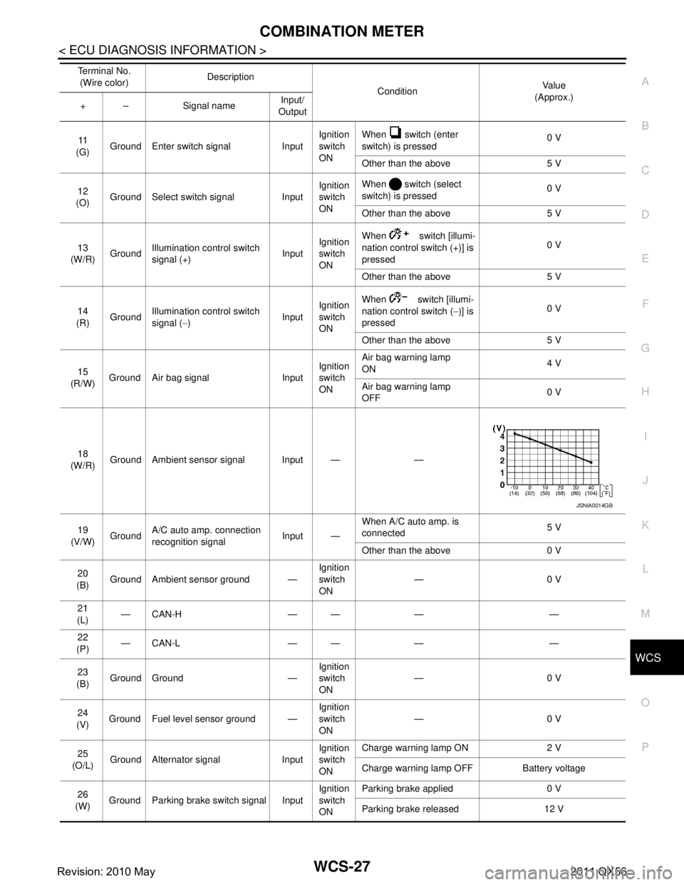
11
(G) Ground Enter switch signal Input Ignition
switch
ONWhen switch (enter
switch) is pressed
0 V
Other than the above 5 V
12
(O) Ground Select switch signal Input Ignition
switch
ONWhen switch (select
switch) is pressed
0 V
Other than the above 5 V
13
(W/R) Ground
Illumination control switch
signal (+) InputIgnition
switch
ON When switch [illumi-
nation control switch (+)] is
pressed
0 V
Other than the above 5 V
14
(R) Ground Illumination control switch
signal (
−) InputIgnition
switch
ON When switch [illumi-
nation control switch (
−)] is
pressed 0 V
Other than the above 5 V
15
(R/W) Ground Air bag signal Input Ignition
switch
ONAir bag warning lamp
ON
4 V
Air bag warning lamp
OFF 0 V
18
(W/R) Ground Ambient sensor signal Input — —
19
(V/W) Ground A/C auto amp. connection
recognition signal Input —When A/C auto amp. is
connected
5 V
Other than the above 0 V
20
(B) Ground Ambient sensor ground — Ignition
switch
ON—0 V
21
(L) —CAN-H — — — —
22
(P) —CAN-L — — — —
23
(B) Ground Ground — Ignition
switch
ON
—0 V
24
(V) Ground Fuel level sensor ground — Ignition
switch
ON—0 V
25
(O/L) Ground Alternator signal Input Ignition
switch
ONCharge warning lamp ON 2 V
Charge warning lamp OFF Battery voltage
26
(W) Ground Parking brake switch signal Input Ignition
switch
ONParking brake applied 0 V
Parking brake released 12 V
Te r m i n a l N o .
(Wire color) Description
ConditionVa l u e
(Approx.)
+ – Signal name Input/
Output
JSNIA0014GB
Revision: 2010 May2011 QX56
Page 5441 of 5598
WCS
DIAGNOSIS AND REPAIR WORKFLOWWCS-37
< BASIC INSPECTION >
C
DE
F
G H
I
J
K L
M B A
O P
BASIC INSPECTION
DIAGNOSIS AND REPAIR WORKFLOW
Work FlowINFOID:0000000006222526
OVERALL SEQUENCE
DETAILED FLOW
1.OBTAIN INFORMATION ABOUT SYMPTOM
Interview the customer to obtain as much informa tion as possible about the conditions and environment under
which the malfunction occurred.
>> GO TO 2.
2.CHECK SYMPTOM
Check the symptom based on the information obtained from the customer.
Check if any other ma lfunctions are present.
>> GO TO 3.
3.CHECK CONSULT-III SELF -DIAGNOSIS RESULTS
Connect CONSULT-III and perform self-diagnosis. Refer to MWI-43, "
DTC Index".
JSNIA0733GB
Revision: 2010 May2011 QX56
Page 5444 of 5598
WCS-40
< DTC/CIRCUIT DIAGNOSIS >
METER BUZZER CIRCUIT
METER BUZZER CIRCUIT
Component Function CheckINFOID:0000000006222528
1.CHECK OPERATION OF METER BUZZER
1. Select “BUZZER” of “BCM” on CONSULT-III.
2. Perform “LIGHT WARN ALM” of “Active Test”.
Does meter buzzer beep?
YES >> INSPECTION END
NO >> GO TO 2.
2.CHECK COMBINATION METER INPUT SIGNAL
Select the “Data Monitor” for the “METER/M&A” and check the “BUZZER” monitor value.
Is the inspection result normal?
YES >> Replace combination meter.
NO >> Replace BCM. Refer to BCS-81, "
Removal and Installation".
Diagnosis ProcedureINFOID:0000000006222529
1.CHECK POWER SUPPLY OF COMBINATION METER
Check power supply of combination meter. Refer to MWI-64, "
COMBINATION METER : Diagnosis Proce-
dure".
Is the inspection result normal?
YES >> INSPECTION END
NO >> Repair power supply circuit of combination meter.
BUZZER
Under the condition of buzzer input : On
Except above : Off
Revision: 2010 May2011 QX56
Page 5445 of 5598

WCS
SEAT BELT BUCKLE SWITCH SIGNAL CIRCUIT
WCS-41
< DTC/CIRCUIT DIAGNOSIS >
C
D E
F
G H
I
J
K L
M B A
O P
SEAT BELT BUCKLE SWITCH SIGNAL CIRCUIT
Component Function CheckINFOID:0000000006222691
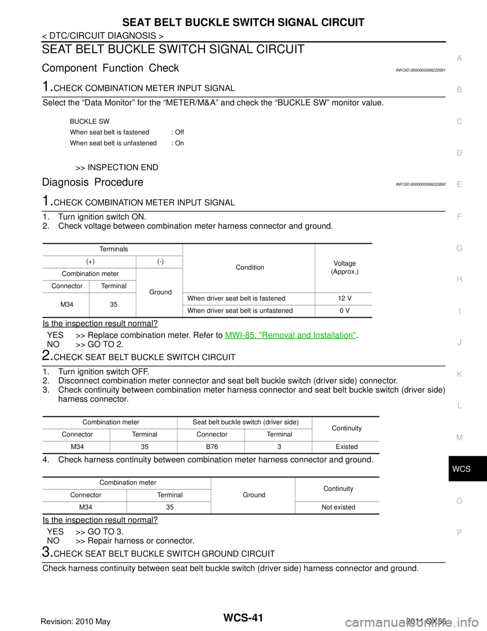
1.CHECK COMBINATION METER INPUT SIGNAL
Select the “Data Monitor” for the “METER/M& A” and check the “BUCKLE SW” monitor value.
>> INSPECTION END
Diagnosis ProcedureINFOID:0000000006222692
1.CHECK COMBINATION METER INPUT SIGNAL
1. Turn ignition switch ON.
2. Check voltage between combination meter harness connector and ground.
Is the inspection result normal?
YES >> Replace combination meter. Refer to MWI-85, "Removal and Installation".
NO >> GO TO 2.
2.CHECK SEAT BELT BUCKLE SWITCH CIRCUIT
1. Turn ignition switch OFF.
2. Disconnect combination meter connector and seat belt buckle switch (driver side) connector.
3. Check continuity between combination meter harnes s connector and seat belt buckle switch (driver side)
harness connector.
4. Check harness continuity between comb ination meter harness connector and ground.
Is the inspection result normal?
YES >> GO TO 3.
NO >> Repair harness or connector.
3.CHECK SEAT BELT BUCKLE SWITCH GROUND CIRCUIT
Check harness continuity between seat belt buckle switch (driver side) harness connector and ground.
BUCKLE SW
When seat belt is fastened : Off
When seat belt is unfastened : On
Te r m i n a l s ConditionVol tag e
(Approx.)
(+) (-)
Combination meter
Ground
Connector Terminal
M34 35 When driver seat belt is fastened 12 V
When driver seat belt is unfastened 0 V
Combination meter Seat belt buckle switch (driver side)
Continuity
Connector Terminal Connector Terminal
M34 35 B76 3 Existed
Combination meter GroundContinuity
Connector Terminal
M34 35 Not existed
Revision: 2010 May2011 QX56
Page 5446 of 5598
WCS-42
< DTC/CIRCUIT DIAGNOSIS >
SEAT BELT BUCKLE SWITCH SIGNAL CIRCUIT
Is the inspection result normal?
YES >> INSPECTION END
NO >> Repair harness or connector.
Component InspectionINFOID:0000000006222693
1.CHECK SEAT BELT BUCKLE SWITCH (DRIVER SIDE)
1. Turn ignition switch OFF.
2. Disconnect the seat belt buckle switch (driver side) connector.
3. Check continuity between terminals.
Is the inspection result normal?
YES >> INSPECTION END
NO >> Replace seat belt buckle (driver side). Refer to SB-8, "
SEAT BELT BUCKLE : Removal and Instal-
lation".
Seat belt buckle switch (driver side)
GroundContinuity
Connector Terminal
B76 4 Existed
Terminal Condition Continuity
34 When seat belt is fastened Not existed
When seat belt is unfastened Existed
Revision: 2010 May2011 QX56
Page 5447 of 5598

WCS
PARKING BRAKE SWITCH SIGNAL CIRCUITWCS-43
< DTC/CIRCUIT DIAGNOSIS >
C
DE
F
G H
I
J
K L
M B A
O P
PARKING BRAKE SWITCH SIGNAL CIRCUIT
Diagnosis ProcedureINFOID:0000000006222530
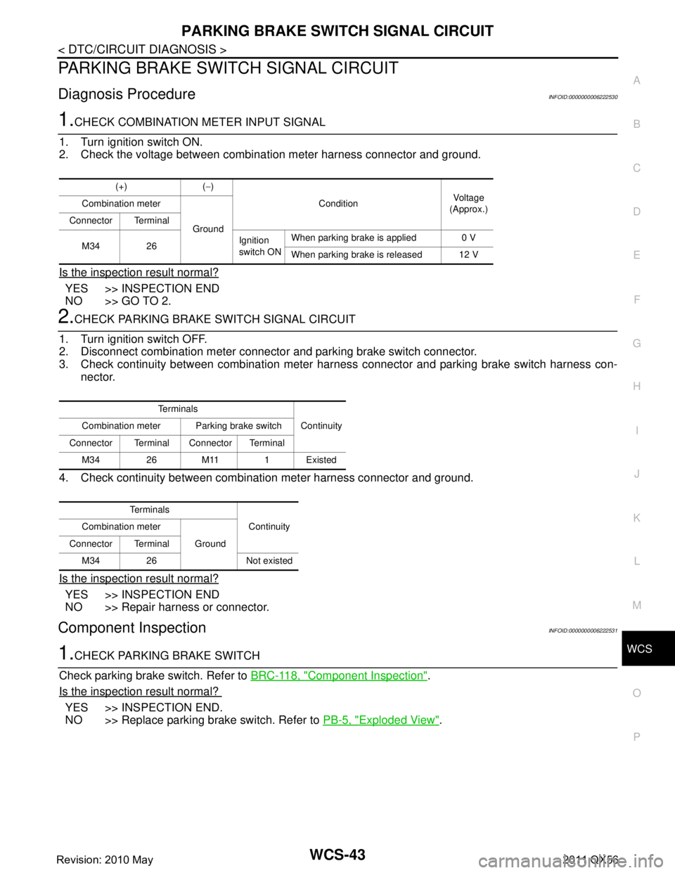
1.CHECK COMBINATION METER INPUT SIGNAL
1. Turn ignition switch ON.
2. Check the voltage between combination meter harness connector and ground.
Is the inspection result normal?
YES >> INSPECTION END
NO >> GO TO 2.
2.CHECK PARKING BRAKE SWITCH SIGNAL CIRCUIT
1. Turn ignition switch OFF.
2. Disconnect combination meter connecto r and parking brake switch connector.
3. Check continuity between combination meter har ness connector and parking brake switch harness con-
nector.
4. Check continuity between combination meter harness connector and ground.
Is the inspection result normal?
YES >> INSPECTION END
NO >> Repair harness or connector.
Component InspectionINFOID:0000000006222531
1.CHECK PARKING BRAKE SWITCH
Check parking brake switch. Refer to BRC-118, "
Component Inspection".
Is the inspection result normal?
YES >> INSPECTION END.
NO >> Replace parking brake switch. Refer to PB-5, "
Exploded View".
(+) (−)
Condition Vo l ta g e
(Approx.)
Combination meter
Ground
Connector Terminal
M34 26 Ignition
switch ONWhen parking brake is applied 0 V
When parking brake is released 12 V
Te r m i n a l s
Continuity
Combination meter Parking brake switch
Connector Terminal Connector Terminal M34 26 M11 1 Existed
Te r m i n a l s Continuity
Combination meter
Ground
Connector Terminal
M34 26 Not existed
Revision: 2010 May2011 QX56
Page 5449 of 5598

WCS
THE SEAT BELT WARNING CONTINUES SOUNDING, OR DOES NOT SOUND
WCS-45
< SYMPTOM DIAGNOSIS >
C
D E
F
G H
I
J
K L
M B A
O P
THE SEAT BELT WARNING CONTIN UES SOUNDING, OR DOES NOT
SOUND
DescriptionINFOID:0000000006222694
Seat belt warning chime does not sound.
Seat belt warning chime sounds continuously.
Diagnosis ProcedureINFOID:0000000006222695
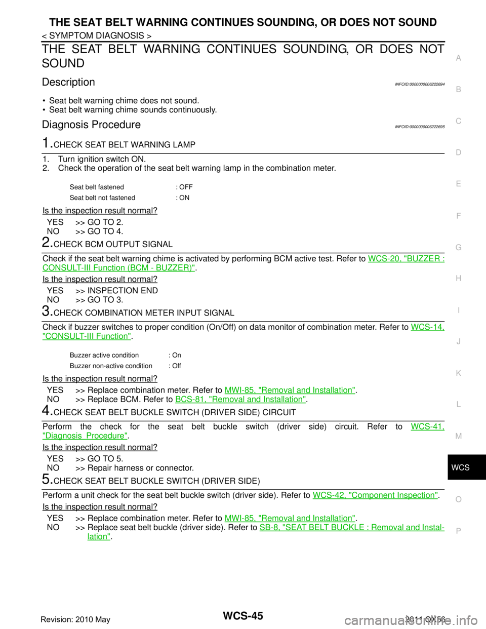
1.CHECK SEAT BELT WARNING LAMP
1. Turn ignition switch ON.
2. Check the operation of the seat belt warning lamp in the combination meter.
Is the inspection result normal?
YES >> GO TO 2.
NO >> GO TO 4.
2.CHECK BCM OUTPUT SIGNAL
Check if the seat belt warning chime is acti vated by performing BCM active test. Refer to WCS-20, "
BUZZER :
CONSULT-III Function (BCM - BUZZER)".
Is the inspection result normal?
YES >> INSPECTION END
NO >> GO TO 3.
3.CHECK COMBINATION METER INPUT SIGNAL
Check if buzzer switches to proper condition (On/Off) on data monitor of combination meter. Refer to WCS-14,
"CONSULT-III Function".
Is the inspection result normal?
YES >> Replace combination meter. Refer to MWI-85, "Removal and Installation".
NO >> Replace BCM. Refer to BCS-81, "
Removal and Installation".
4.CHECK SEAT BELT BUCKLE SWITCH (DRIVER SIDE) CIRCUIT
Perform the check for the seat belt buckle switch (driver side) circuit. Refer to WCS-41,
"DiagnosisProcedure".
Is the inspection result normal?
YES >> GO TO 5.
NO >> Repair harness or connector.
5.CHECK SEAT BELT BUCKLE SWITCH (DRIVER SIDE)
Perform a unit check for the seat belt buckle switch (driver side). Refer to WCS-42, "
Component Inspection".
Is the inspection result normal?
YES >> Replace combination meter. Refer to MWI-85, "Removal and Installation".
NO >> Replace seat belt buckle (driver side). Refer to SB-8, "
SEAT BELT BUCKLE : Removal and Instal-
lation".
Seat belt fastened : OFF
Seat belt not fastened : ON
Buzzer active condition : On
Buzzer non-active condition : Off
Revision: 2010 May2011 QX56