2011 INFINITI QX56 ground
[x] Cancel search: groundPage 261 of 5598

AV
CALIBRATING CAMERA IMAGE (AROUND VIEW MONITOR)
AV-113
< BASIC INSPECTION >
C
D E
F
G H
I
J
K L
M B A
O P
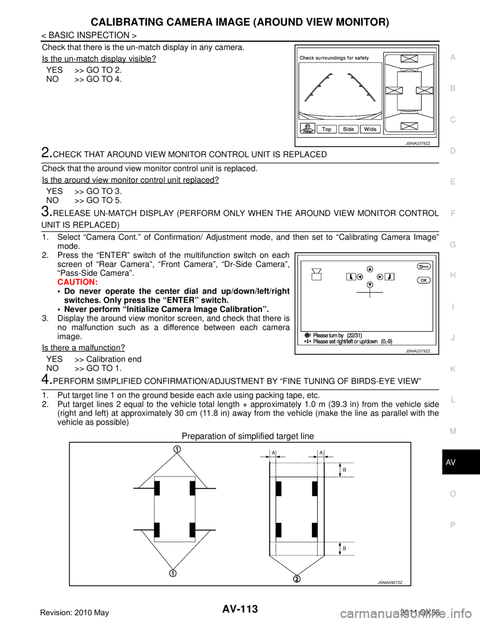
Check that there is the un-match display in any camera.
Is the un-match display visible?
YES >> GO TO 2.
NO >> GO TO 4.
2.CHECK THAT AROUND VIEW MONITOR CONTROL UNIT IS REPLACED
Check that the around view monitor control unit is replaced.
Is the around view monitor control unit replaced?
YES >> GO TO 3.
NO >> GO TO 5.
3.RELEASE UN-MATCH DISPLAY (PERFORM ONLY WHEN THE AROUND VIEW MONITOR CONTROL
UNIT IS REPLACED)
1. Select “Camera Cont.” of Confirmation/ Adjust ment mode, and then set to “Calibrating Camera Image”
mode.
2. Press the “ENTER” switch of the multifunction switch on each screen of “Rear Camera”, “Front Camera”, “Dr-Side Camera”\
,
“Pass-Side Camera”.
CAUTION:
Do never operate the center dial and up/down/left/right
switches. Only press the “ENTER” switch.
Never perform “Initialize Camera Image Calibration”.
3. Display the around view monitor screen, and check that there is
no malfunction such as a difference between each camera
image.
Is there a malfunction?
YES >> Calibration end
NO >> GO TO 1.
4.PERFORM SIMPLIFIED CONFIRMATION/ADJUSTM ENT BY “FINE TUNING OF BIRDS-EYE VIEW”
1. Put target line 1 on the ground beside each axle using packing tape, etc.
2. Put target lines 2 equal to the vehicle total length + approximately 1.0 m (39.3 in) from the vehicle side
(right and left) at approximately 30 cm (11.8 in) away from the vehicle (make the line as parallel with the
vehicle as possible)
Preparation of simplified target line
JSNIA2378ZZ
JSNIA2379ZZ
JSNIA0927ZZ
Revision: 2010 May2011 QX56
Page 262 of 5598

AV-114
< BASIC INSPECTION >
CALIBRATING CAMERA IMAGE (AROUND VIEW MONITOR)
3. Select “Camera Cont.” of Confirmation/ Adjustment mode, and then set to “Fine Tuning of Birds-Eye View”
mode.
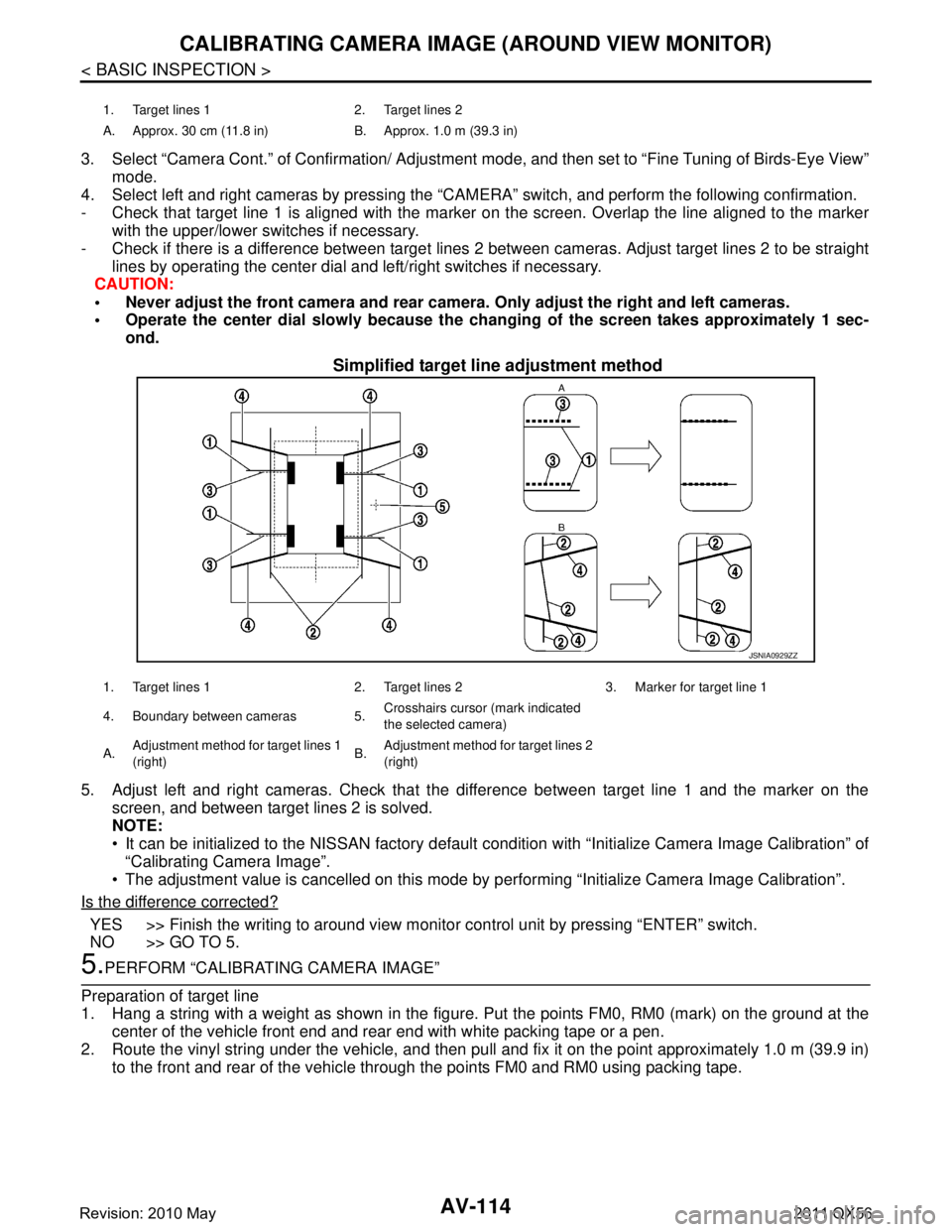
4. Select left and right cameras by pressing the “CAM ERA” switch, and perform the following confirmation.
- Check that target line 1 is aligned with the marker on the screen. Overlap the line aligned to the marker
with the upper/lower switches if necessary.
- Check if there is a difference between target lines 2 between cameras. Adjust target lines 2 to be straight
lines by operating the center dial and left/right switches if necessary.
CAUTION:
Never adjust the front camera and rear camer a. Only adjust the right and left cameras.
Operate the center dial slowly because the ch anging of the screen takes approximately 1 sec-
ond.
Simplified target line adjustment method
5. Adjust left and right cameras. Check that the difference between target line 1 and the marker on the
screen, and between target lines 2 is solved.
NOTE:
It can be initialized to the NISSAN factory default c ondition with “Initialize Camera Image Calibration” of
“Calibrating Camera Image”.
The adjustment value is cancelled on this mode by performing “Initialize Camera Image Calibration”.
Is the difference corrected?
YES >> Finish the writing to around view monito r control unit by pressing “ENTER” switch.
NO >> GO TO 5.
5.PERFORM “CALIBRATING CAMERA IMAGE”
Preparation of target line
1. Hang a string with a weight as shown in the figure. Put the points FM0, RM0 (mark) on the ground at the
center of the vehicle front end and rear end with white packing tape or a pen.
2. Route the vinyl string under the vehicle, and then pull and fix it on the point approximately 1.0 m (39.9 in)
to the front and rear of the vehicle through the points FM0 and RM0 using packing tape.
1. Target lines 1 2. Target lines 2
A. Approx. 30 cm (11.8 in) B. Approx. 1.0 m (39.3 in)
JSNIA0929ZZ
1. Target lines 1 2. Target lines 2 3. Marker for target line 1
4. Boundary between cameras 5. Crosshairs cursor (mark indicated
the selected camera)
A. Adjustment method for target lines 1
(right) B.
Adjustment method for target lines 2
(right)
Revision: 2010 May2011 QX56
Page 264 of 5598

AV-116
< BASIC INSPECTION >
CALIBRATING CAMERA IMAGE (AROUND VIEW MONITOR)
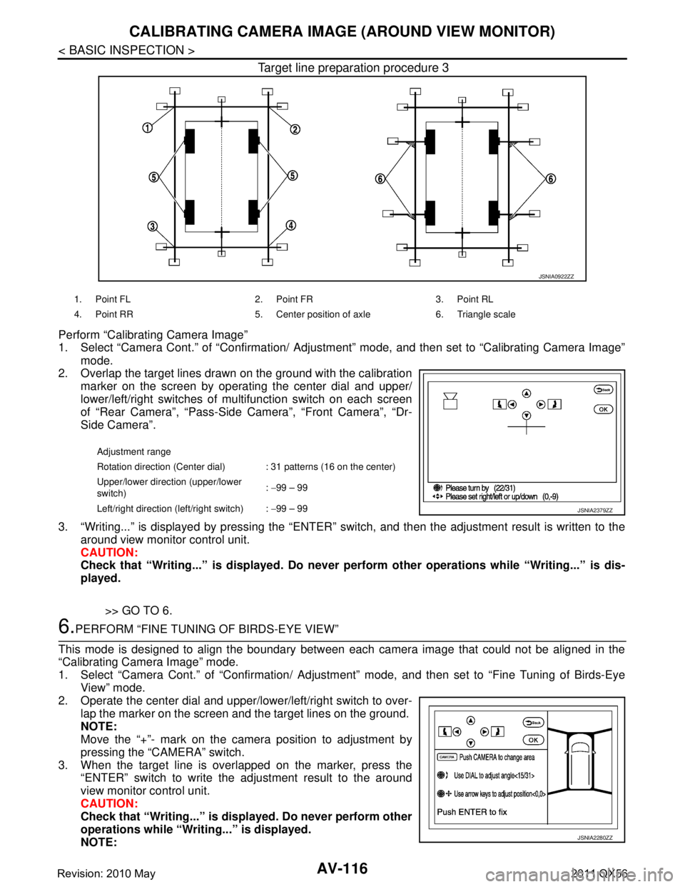
Target line preparation procedure 3
Perform “Calibrating Camera Image”
1. Select “Camera Cont.” of “Confirmation/ Adjustment” mode, and then set to “Calibrating Camera Image”
mode.
2. Overlap the target lines drawn on the ground with the calibration
marker on the screen by operating the center dial and upper/
lower/left/right switches of multifunction switch on each screen
of “Rear Camera”, “Pass-Side Camera”, “Front Camera”, “Dr-
Side Camera”.
3. “Writing...” is displayed by pressing the “ENTER” s witch, and then the adjustment result is written to the
around view monitor control unit.
CAUTION:
Check that “Writing...” is displayed . Do never perform other operations while “Writing...” is dis-
played.
>> GO TO 6.
6.PERFORM “FINE TUNING OF BIRDS-EYE VIEW”
This mode is designed to align the boundary between each camera image that could not be aligned in the
“Calibrating Camera Image” mode.
1. Select “Camera Cont.” of “Confirmation/ Adjustm ent” mode, and then set to “Fine Tuning of Birds-Eye
View” mode.
2. Operate the center dial and upper/l ower/left/right switch to over-
lap the marker on the screen and the target lines on the ground.
NOTE:
Move the “+”- mark on the camera position to adjustment by
pressing the “CAMERA” switch.
3. When the target line is overlapped on the marker, press the “ENTER” switch to write the adjustment result to the around
view monitor control unit.
CAUTION:
Check that “Writing...” is disp layed. Do never perform other
operations while “Writing...” is displayed.
NOTE:
JSNIA0922ZZ
1. Point FL 2. Point FR 3. Point RL
4. Point RR 5. Center position of axle 6. Triangle scale
Adjustment range
Rotation direction (Center dial) : 31 patterns (16 on the center)
Upper/lower direction (upper/lower
switch) :
−99 – 99
Left/right direction (left/right switch) : −99 – 99
JSNIA2379ZZ
JSNIA2280ZZ
Revision: 2010 May2011 QX56
Page 291 of 5598

AV
U1243 FRONT DISPLAY UNITAV-143
< DTC/CIRCUIT DIAGNOSIS >
C
DE
F
G H
I
J
K L
M B A
O P
U1243 FRONT DISPLAY UNIT
DTC LogicINFOID:0000000006216293
Diagnosis ProcedureINFOID:0000000006216294
1.CHECK FRONT DISPLAY UNIT POWER SUPPLY AND GROUND CIRCUITS
Check front display unit power s upply and ground circuits. Refer to AV-161, "
FRONT DISPLAY UNIT : Diagno-
sis Procedure".
Is inspection result normal?
YES >> GO TO 2.
NO >> Repair malfunctioning parts.
2.CHECK CONTINUITY CO MMUNICATION CIRCUITS
1. Turn ignition switch OFF.
2. Disconnect front display unit connector and AV control unit connector.
3. Check continuity between front display unit harness connector and AV control unit harness connector.
4. Check continuity between front display unit harness connector and ground.
Is inspection result normal?
YES >> GO TO 3.
NO >> Repair harness or connector.
3.CHECK COMMUNICATION SIGNAL
1. Connect front display unit connector and AV control unit connector.
2. Turn ignition switch ON.
3. Check signal between front display unit harness connector and ground.
DTC Display contents of
CONSULT-III DTC Detection Condit
ion Possible causes
U1243 FRONT DISP CONN
[U1243] When either one of the following items is detected.
front display unit power supply and ground circuits are
malfunctioning.
serial communication circuits between front display unit and AV control unit are malfunctioning. Front display unit power supply and
ground circuits.
Serial communication circuits be- tween front display unit and AV
control unit.
Front display unit AV control unit Continuity
Connector Terminals Connector Terminals
M215 9
M210 89
Existed
10 73
Front display unit GroundContinuity
Connector Terminals
M215 9
Not existed
10
Revision: 2010 May2011 QX56
Page 292 of 5598

AV-144
< DTC/CIRCUIT DIAGNOSIS >
U1243 FRONT DISPLAY UNIT
Is inspection result normal?
YES >> GO TO 4.
NO >> Replace AV control unit. Refer to AV-212, "
Removal and Installation".
4.CHECK COMMUNICATION SIGNAL
Check signal between front display unit harness connector and ground.
Is inspection result normal?
YES >> INSPECTION END
NO >> Replace front display unit. Refer to AV-213, "
Removal and Installation".
(+)
(− ) Condition Reference value
Front display unit
Connector Terminal
M215 9 Ground When adjusting display bright-
ness.
PKIB5039J
(+)
(− ) Condition Reference value
Front display unit
Connector Terminal
M215 10 Ground When adjusting display bright-
ness.
PKIB5039J
Revision: 2010 May2011 QX56
Page 293 of 5598

AV
U1244 GPS ANTENNAAV-145
< DTC/CIRCUIT DIAGNOSIS >
C
DE
F
G H
I
J
K L
M B A
O P
U1244 GPS ANTENNA
DTC LogicINFOID:0000000006216295
Diagnosis ProcedureINFOID:0000000006216296
1.GPS ANTENNA CHECK
Visually check GPS antenna and antenna feeder.
Is inspection result normal?
YES >> GO TO 2.
NO >> Repair malfunctioning parts.
2.CHECK AV CONTROL UNIT VOLTAGE
1. Disconnect GPS antenna connector.
2. Turn ignition switch ON.
3. Check voltage between AV control unit terminal and ground.
Is inspection result normal?
YES >> INSPECTION END
NO >> Replace AV control unit. Refer to AV-212, "
Removal and Installation".
DTCDisplay contents of
CONSULT-III DTC Detection Condit
ion Possible causes
U1244 GPS ANTENNA CONN
[U1244] GPS antenna connection malfunction is detected. GPS antenna disconnection
(+)
(− ) Vol tag e
(Approx.)
AV c o n t r o l u n i t
Te r m i n a l153 Ground 5.0 V
Revision: 2010 May2011 QX56
Page 294 of 5598

AV-146
< DTC/CIRCUIT DIAGNOSIS >
U1258 SATELLITE RADIO ANTENNA
U1258 SATELLITE RADIO ANTENNA
DTC LogicINFOID:0000000006226137
Diagnosis ProcedureINFOID:0000000006226138
1.SATELLITE RADIO ANTENNA CHECK
Visually check satellite radio antenna and antenna feeder.
Is the inspection result normal?
YES >> GO TO 2.
NO >> Repair malfunctioning parts.
2.CHECK AV CONTROL UNIT VOLTAGE
1. Disconnect satellite radio antenna connector.
2. Turn ignition switch ON.
3. Check voltage between AV control unit and ground.
Is the inspection result normal?
YES >> INSPECTION END
NO >> Replace AV control unit. Refer to AV-212, "
Removal and Installation".
DTCDisplay contents of
CONSULT-III DTC Detection Condition Possible causes
U1258 XM ANTENNA CONN
[U1258] Satellite radio antenna connection malfunction is detect-
ed.
Satellite radio antenna disconnection.
(+)
(− ) Vo l ta g e
(Approx.)
AV c o n t r o l u n i t
Te r m i n a l159 Ground 5.0 V
Revision: 2010 May2011 QX56
Page 295 of 5598

AV
U125A HEADREST DISPLAY UNITAV-147
< DTC/CIRCUIT DIAGNOSIS >
C
DE
F
G H
I
J
K L
M B A
O P
U125A HEADREST DISPLAY UNIT
DTC LogicINFOID:0000000006216297
Diagnosis ProcedureINFOID:0000000006216298
1.CHECK HEADREST DISPLAY UNIT RH POWER SUPPLY AND GROUND CIRCUIT
Check headrest display unit RH power supply and ground circuits. Refer to AV-162, "
HEADREST DISPLAY
UNIT : Diagnosis Procedure".
Is the inspection result normal?
YES >> GO TO 2.
NO >> Repair malfunctioning parts.
2.CHECK CONTINUITY AV COMMUNICATION CIRCUIT
1. Turn ignition switch OFF.
2. Disconnect headrest display unit LH connector and headrest display unit RH connector.
3. Check continuity between headrest display unit LH harness connector and headrest display unit RH har- ness connector.
Is the inspection result normal?
YES >> GO TO 3.
NO >> Repair harness or connector.
3.CHECK LOCATION RECOGNITION SIGNAL CIRCUIT
Check location recognition signal circuit between headrest display unit RH and ground. Refer to AV-175,
"Diagnosis Procedure".
Is the inspection result normal?
YES >> Replace headrest display unit RH. Refer to AV-214, "Exploded View".
NO >> Repair harness or connector.
DTC Display contents of
CONSULT-III DTC Detection Condit
ion Possible causes
U125A 3RD DISP CONN
[U125A] When either one of the following items are detected:
headrest display unit RH power supply and ground cir-
cuits are malfunctioning.
AV communication circuits between headrest display unit LH and headrest display unit RH are malfunction-
ing.
location recognition signal circuit between headrest dis- play unit RH and ground is malfunctioning. Headrest display unit RH power
supply and ground circuits.
AV communication circuits be- tween Headrest display unit LH and
headrest display unit RH.
Location recognition signal circuit between headrest display unit RH
and ground.
Headrest display unit LH Headrest display unit RH Continuity
Connector Terminals Connector Terminals
B554 11
B574 12
Existed
13 14
Revision: 2010 May2011 QX56