2011 INFINITI QX56 engine coolant
[x] Cancel search: engine coolantPage 2605 of 5598
HIGH PRESSURE FUEL PUMP AND FUEL HOSEEM-43
< REMOVAL AND INSTALLATION >
C
DE
F
G H
I
J
K L
M A
EM
NP
O
HIGH PRESSURE FUEL
PUMP AND FUEL HOSE
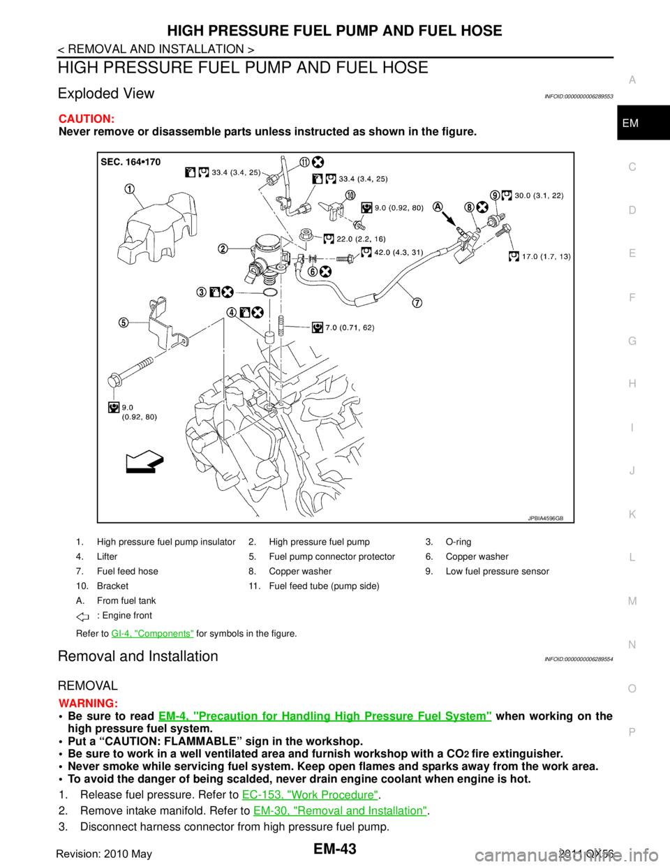
Exploded ViewINFOID:0000000006289553
CAUTION:
Never remove or disassemble parts unless instructed as shown in the figure.
Removal and InstallationINFOID:0000000006289554
REMOVAL
WARNING:
Be sure to read EM-4, "
Precaution for Handling High Pressure Fuel System" when working on the
high pressure fuel system.
Put a “CAUTION: FLAMMABLE” sign in the workshop.
Be sure to work in a well ventila ted area and furnish workshop with a CO
2 fire extinguisher.
Never smoke while servicing fuel system. Keep op en flames and sparks away from the work area.
To avoid the danger of being scalded, never drain engine coolant when engine is hot.
1. Release fuel pressure. Refer to EC-153, "
Work Procedure".
2. Remove intake manifold. Refer to EM-30, "
Removal and Installation".
3. Disconnect harness connector from high pressure fuel pump.
1. High pressure fuel pump insulator 2. High pressure fuel pump 3. O-ring
4. Lifter 5. Fuel pump connector protector 6. Copper washer
7. Fuel feed hose 8. Copper washer 9. Low fuel pressure sensor
10. Bracket 11. Fuel feed tube (pump side)
A. From fuel tank
: Engine front
Refer to GI-4, "
Components" for symbols in the figure.
JPBIA4596GB
Revision: 2010 May2011 QX56
Page 2611 of 5598
FUEL INJECTOR AND FUEL TUBEEM-49
< REMOVAL AND INSTALLATION >
C
DE
F
G H
I
J
K L
M A
EM
NP
O
Removal and InstallationINFOID:0000000006289557
REMOVAL
WARNING:
Be sure to read
EM-4, "
Precaution for Handling High Pressure Fuel System" when working on the
high pressure fuel system.
Put a “CAUTION: FLAMMABLE” sign in the workshop.
Be sure to work in a well ventila ted area and furnish workshop with a CO
2 fire extinguisher.
Never smoke while servicing fuel system. Keep op en flames and sparks away from the work area.
To avoid the danger of being scalded, never drain engine coolant when engine is hot.
1. Release fuel pressure. Refer to EC-153, "
Work Procedure".
2. Remove intake manifold. Refer to EM-30, "
Removal and Installation".
3. Remove fuel feed tube (pump side) and fuel feed tube (bank side). CAUTION:
Never reuse fuel feed tube.
4. Remove fuel rail (bank 1) and fuel rail (bank 2).
5. Disconnect harness connector from fuel injectors.
6. Remove fuel injector from cylinder head as per the following: CAUTION:
Be careful with remaining fuel th at may go out from fuel tube.
Be careful not to damage in jector nozzles during removal.
Never bump or drop fuel injector.
Never disassemble fuel injector.
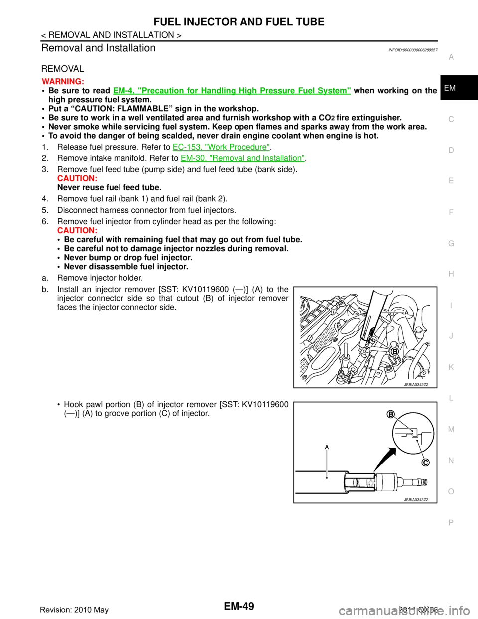
a. Remove injector holder.
b. Install an injector remover [SST: KV10119600 (—)] (A) to the injector connector side so that cutout (B) of injector remover
faces the injector connector side.
Hook pawl portion (B) of injector remover [SST: KV10119600(—)] (A) to groove portion (C) of injector.
JSBIA0342ZZ
JSBIA0343ZZ
Revision: 2010 May2011 QX56
Page 2624 of 5598
EM-62
< REMOVAL AND INSTALLATION >
TIMING CHAIN
Removal and Installation
INFOID:0000000006289566
REMOVAL
1. Release fuel pressure. Refer to EC-153, "Work Procedure".
2. Drain engine coolant from radiator. Refer to CO-8, "
Draining".
3. Remove fan shroud (lower). Refer to CO-13, "
Exploded View".
4. Remove fan bracket. Refer to CO-16, "
Exploded View".
5. Remove drive belt auto-tensioner. Refer to EM-26, "
Exploded View".
6. Remove oil level gauge and oil level gauge guide. Refer to EM-57, "
Exploded View".
7. Move power steering oil pump to the posit ion without the hindrance for work. Refer to ST-48, "
Exploded
View".
8. Remove alternator, alternator bracket and alternator stay. Refer to CHG-25, "
Exploded View".
9. Move power steering reservoir tank to the position without the hindrance for work, and then remove Res- ervoir tank bracket. Refer to ST-54, "
Exploded View".
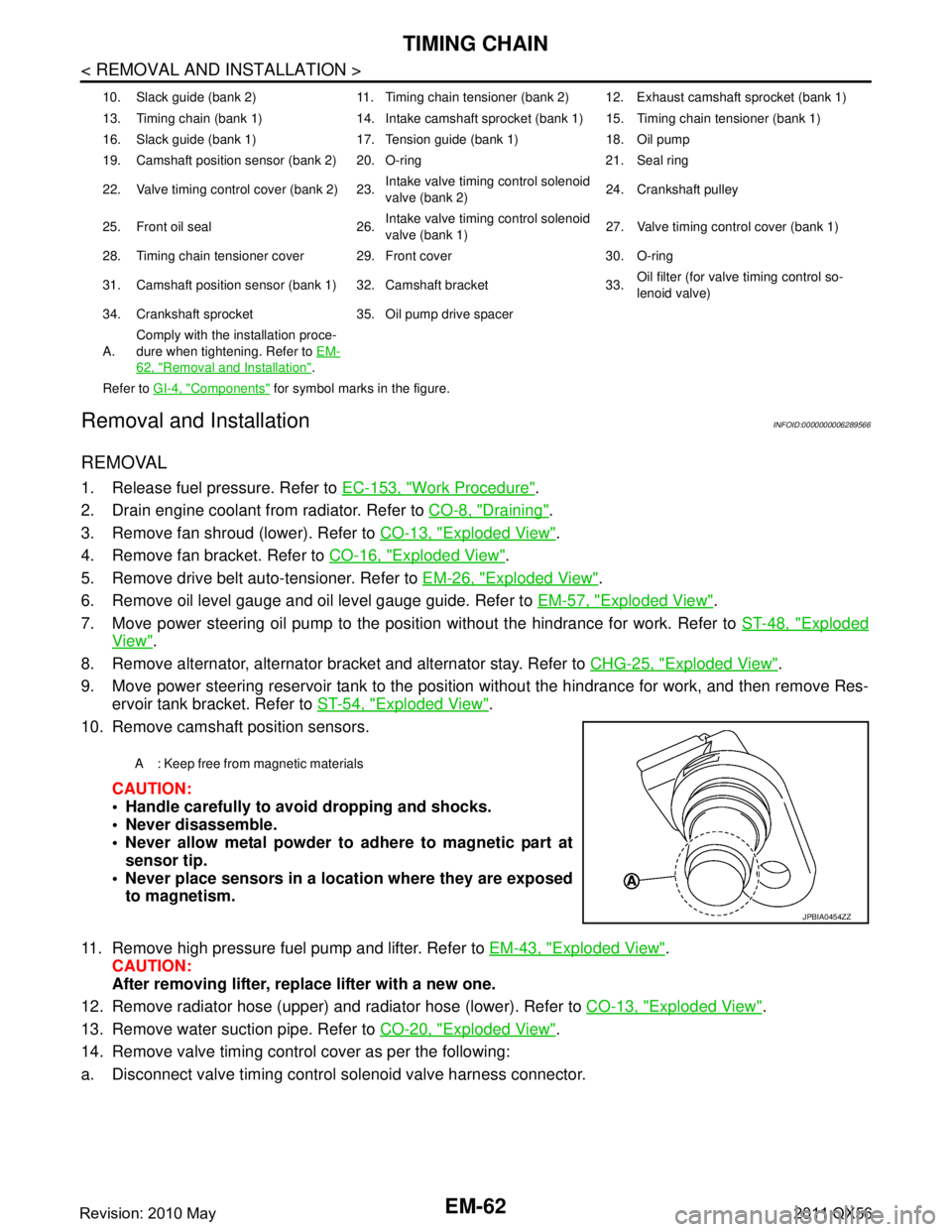
10. Remove camshaft position sensors.
CAUTION:
Handle carefully to avoid dropping and shocks.
Never disassemble.
Never allow metal powder to adhere to magnetic part atsensor tip.
Never place sensors in a lo cation where they are exposed
to magnetism.
11. Remove high pressure fuel pump and lifter. Refer to EM-43, "
Exploded View".
CAUTION:
After removing lifter, replace lifter with a new one.
12. Remove radiator hose (upper) and radiator hose (lower). Refer to CO-13, "
Exploded View".
13. Remove water suction pipe. Refer to CO-20, "
Exploded View".
14. Remove valve timing control cover as per the following:
a. Disconnect valve timing control solenoid valve harness connector.
10. Slack guide (bank 2) 11. Timing chain tensioner (bank 2) 12. Exhaust camshaft sprocket (bank 1)
13. Timing chain (bank 1) 14. Intake camshaft sprocket (bank 1) 15. Timing chain tensioner (bank 1)
16. Slack guide (bank 1) 17. Tension guide (bank 1) 18. Oil pump
19. Camshaft position sensor (bank 2) 20. O-ring 21. Seal ring
22. Valve timing control cover (bank 2) 23. Intake valve timing control solenoid
valve (bank 2)24. Crankshaft pulley
25. Front oil seal 26. Intake valve timing control solenoid
valve (bank 1)27. Valve timing control cover (bank 1)
28. Timing chain tensioner cover 29. Front cover 30. O-ring
31. Camshaft position sensor (bank 1) 32. Camshaft bracket 33. Oil filter (for valve timing control so-
lenoid valve)
34. Crankshaft sprocket 35. Oil pump drive spacer
A. Comply with the installation proce-
dure when tightening. Refer to
EM-
62, "Removal and Installation".
Refer to GI-4, "
Components" for symbol marks in the figure.
A : Keep free from magnetic materials
JPBIA0454ZZ
Revision: 2010 May2011 QX56
Page 2635 of 5598
TIMING CHAINEM-73
< REMOVAL AND INSTALLATION >
C
DE
F
G H
I
J
K L
M A
EM
NP
O
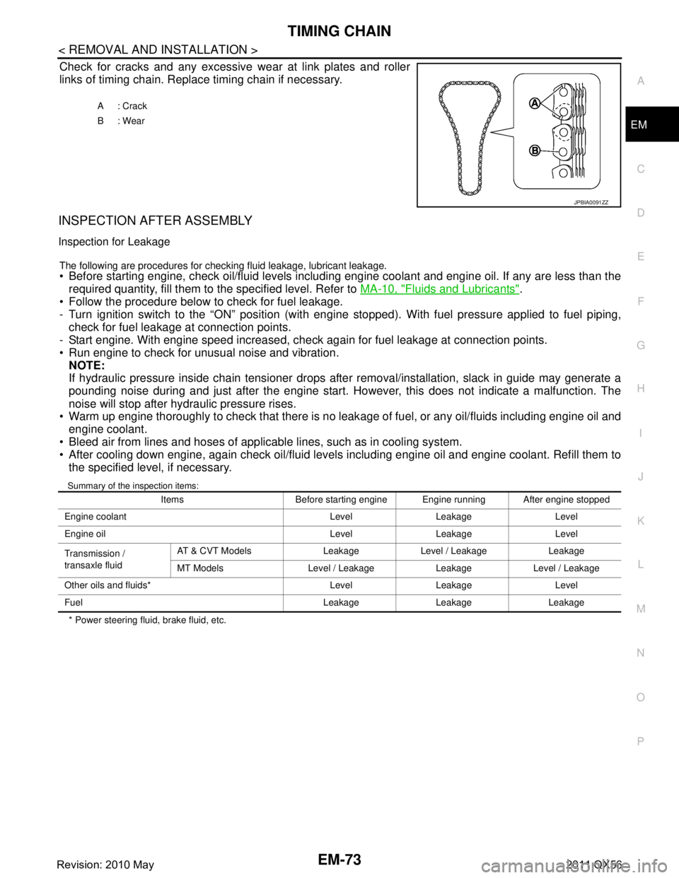
Check for cracks and any excessive
wear at link plates and roller
links of timing chain. Replace timing chain if necessary.
INSPECTION AFTER ASSEMBLY
Inspection for Leakage
The following are procedures for chec king fluid leakage, lubricant leakage. Before starting engine, check oil/fluid levels including engine coolant and engine oil. If any are less than the
required quantity, fill them to the specified level. Refer to MA-10, "
Fluids and Lubricants".
Follow the procedure below to check for fuel leakage.
- Turn ignition switch to the “ON” position (with engi ne stopped). With fuel pressure applied to fuel piping,
check for fuel leakage at connection points.
- Start engine. With engine speed increased, check again for fuel leakage at connection points.
Run engine to check for unusual noise and vibration.
NOTE:
If hydraulic pressure inside chain tensioner drops after removal/installation, slack in guide may generate a
pounding noise during and just after the engine start. However, this does not indicate a malfunction. The
noise will stop after hydraulic pressure rises.
Warm up engine thoroughly to check that there is no leak age of fuel, or any oil/fluids including engine oil and
engine coolant.
Bleed air from lines and hoses of applicable lines, such as in cooling system.
After cooling down engine, again check oil/fluid levels including engine oil and engine coolant. Refill them to the specified level, if necessary.
Summary of the inspection items:
* Power steering fluid, brake fluid, etc. A: Crack
B: Wear
JPBIA0091ZZ
Items Before starting engine Engine running After engine stopped
Engine coolant Level Leakage Level
Engine oil Level Leakage Level
Transmission /
transaxle fluid AT & CVT Models Leakage Level / Leakage Leakage
MT Models Level / Leakage Leakage Level / Leakage
Other oils and fluids* Level Leakage Level
Fuel Leakage Leakage Leakage
Revision: 2010 May2011 QX56
Page 2647 of 5598
CAMSHAFTEM-85
< REMOVAL AND INSTALLATION >
C
DE
F
G H
I
J
K L
M A
EM
NP
O
5. Perform the following inspection if engine oil does not
come out from valve timing control solenoid valve
oil hole of the valve timing control cover.
Remove oil filter, and then clean it. Refer to EM-61, "
Exploded View".
Clean oil groove between oil strainer and valve timing control solenoid valve. Refer to LU-5, "
Engine
Lubrication System" and LU-6, "Engine Lubrication System Schematic".
6. Remove components between valve timing control solenoid valve and camshaft sprocket, and then check each oil groove for clogging.
Clean oil groove if necessary. Refer to LU-5, "
Engine Lubrication System" and LU-6, "Engine Lubrica-
tion System Schematic".
7. After inspection, install removed parts in the reverse order.
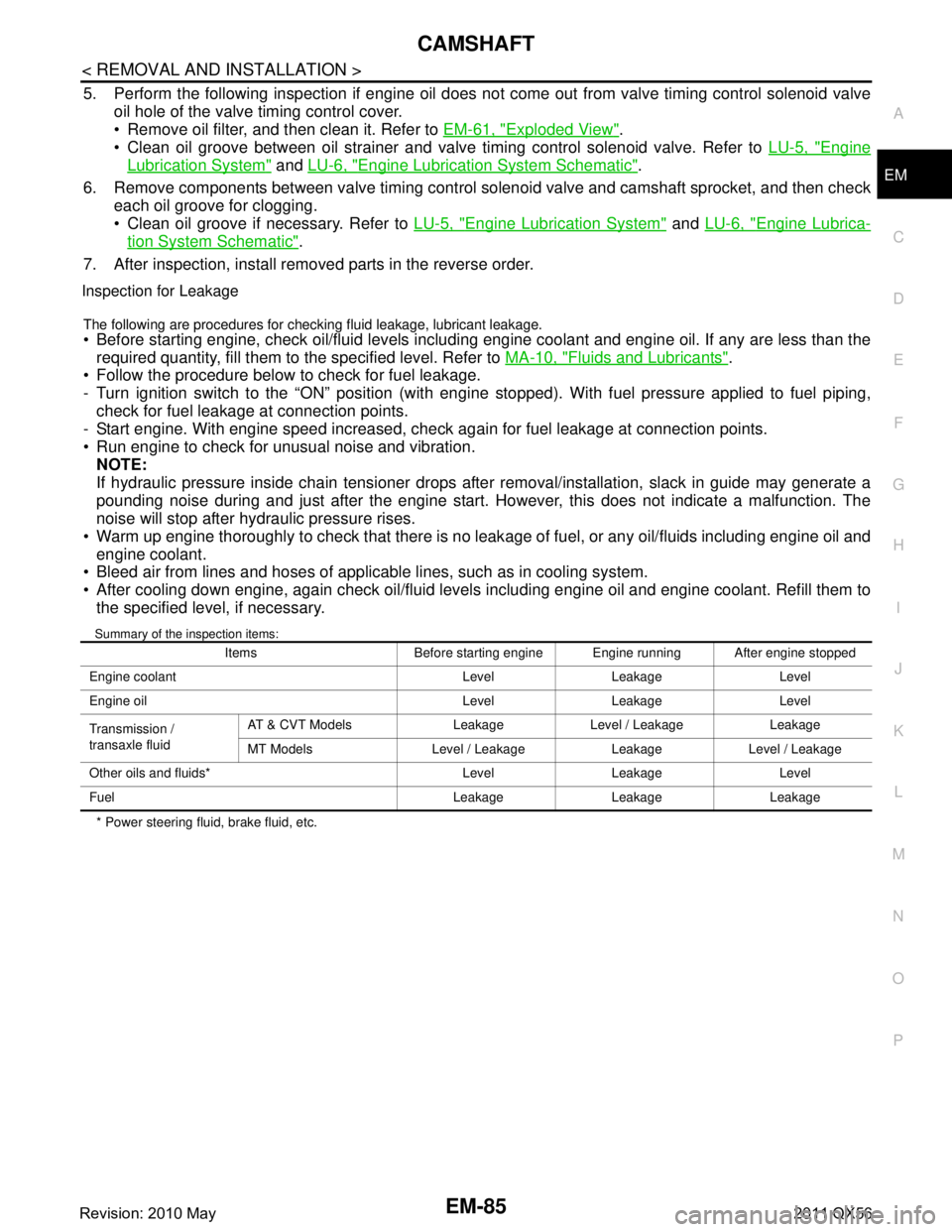
Inspection for Leakage
The following are procedures for chec king fluid leakage, lubricant leakage.
Before starting engine, check oil/fluid levels including engine coolant and engine oil. If any are less than the
required quantity, fill them to the specified level. Refer to MA-10, "
Fluids and Lubricants".
Follow the procedure below to check for fuel leakage.
- Turn ignition switch to the “ON” position (with engi ne stopped). With fuel pressure applied to fuel piping,
check for fuel leakage at connection points.
- Start engine. With engine speed increased, check again for fuel leakage at connection points.
Run engine to check for unusual noise and vibration. NOTE:
If hydraulic pressure inside chain tensioner drops after removal/installation, slack in guide may generate a
pounding noise during and just after the engine start. However, this does not indicate a malfunction. The
noise will stop after hydraulic pressure rises.
Warm up engine thoroughly to check that there is no leak age of fuel, or any oil/fluids including engine oil and
engine coolant.
Bleed air from lines and hoses of applicable lines, such as in cooling system.
After cooling down engine, again check oil/fluid levels including engine oil and engine coolant. Refill them to
the specified level, if necessary.
Summary of the inspection items:
* Power steering fluid, brake fluid, etc. Items Before starting engine Engine running After engine stopped
Engine coolant Level Leakage Level
Engine oil Level Leakage Level
Transmission /
transaxle fluid AT & CVT Models Leakage Level / Leakage Leakage
MT Models Level / Leakage Leakage Level / Leakage
Other oils and fluids* Level Leakage Level
Fuel Leakage Leakage Leakage
Revision: 2010 May2011 QX56
Page 2648 of 5598
EM-86
< REMOVAL AND INSTALLATION >
CYLINDER HEAD
CYLINDER HEAD
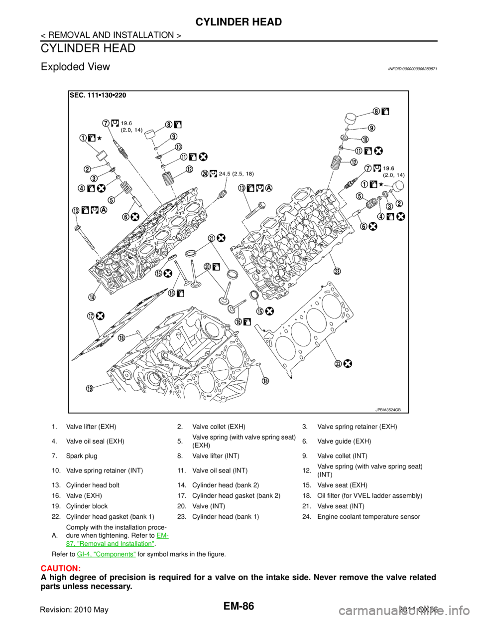
Exploded ViewINFOID:0000000006289571
CAUTION:
A high degree of precision is required for a valve on the intake side. Never remove the valve related
parts unless necessary.
1. Valve lifter (EXH) 2. Valve collet (EXH) 3. Valve spring retainer (EXH)
4. Valve oil seal (EXH) 5. Valve spring (with valve spring seat)
(EXH)6. Valve guide (EXH)
7. Spark plug 8. Valve lifter (INT) 9. Valve collet (INT)
10. Valve spring retainer (INT) 11. Valve oil seal (INT) 12. Valve spring (with valve spring seat)
(INT)
13. Cylinder head bolt 14. Cylinder head (bank 2) 15. Valve seat (EXH)
16. Valve (EXH) 17. Cylinder head gasket (bank 2) 18. Oil filter (for VVEL ladder assembly)
19. Cylinder block 20. Valve (INT) 21. Valve seat (INT)
22. Cylinder head gasket (bank 1) 23. Cylinder head (bank 1) 24. Engine coolant temperature sensor
A. Comply with the installation proce-
dure when tightening. Refer to
EM-
87, "Removal and Installation".
Refer to GI-4, "
Components" for symbol marks in the figure.
JPBIA3524GB
Revision: 2010 May2011 QX56
Page 2655 of 5598
CYLINDER HEADEM-93
< REMOVAL AND INSTALLATION >
C
DE
F
G H
I
J
K L
M A
EM
NP
O
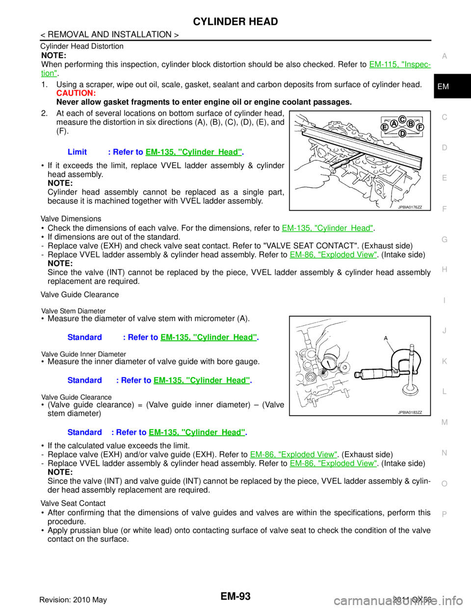
Cylinder Head Distortion
NOTE:
When performing this inspection, cylinder block distortion should be also checked. Refer to
EM-115, "
Inspec-
tion".
1. Using a scraper, wipe out oil, scale, gasket, s ealant and carbon deposits from surface of cylinder head.
CAUTION:
Never allow gasket fragments to enter engine oil or engine coolant passages.
2. At each of several locations on bottom surface of cylinder head, measure the distortion in six directi ons (A), (B), (C), (D), (E), and
(F).
If it exceeds the limit, replace VVEL ladder assembly & cylinder head assembly.
NOTE:
Cylinder head assembly cannot be replaced as a single part,
because it is machined together with VVEL ladder assembly.
Valve Dimensions
Check the dimensions of each valv e. For the dimensions, refer to EM-135, "CylinderHead".
If dimensions are out of the standard.
- Replace valve (EXH) and check valve seat contact. Refer to "VALVE SEAT CONTACT". (Exhaust side)
- Replace VVEL ladder assembly & cylinder head assembly. Refer to EM-86, "
Exploded View". (Intake side)
NOTE:
Since the valve (INT) cannot be replaced by the pi ece, VVEL ladder assembly & cylinder head assembly
replacement are required.
Valve Guide Clearance
Valve Stem Diameter
Measure the diameter of valve stem with micrometer (A).
Valve Guide Inner Diameter
Measure the inner diameter of valve guide with bore gauge.
Valve Guide Clearance
(Valve guide clearance) = (Valve guide inner diameter) – (Valve
stem diameter)
If the calculated value exceeds the limit.
- Replace valve (EXH) and/or valve guide (EXH). Refer to EM-86, "
Exploded View". (Exhaust side)
- Replace VVEL ladder assembly & cylinder head assembly. Refer to EM-86, "
Exploded View". (Intake side)
NOTE:
Since the valve (INT) and valve guide (INT) cannot be repl aced by the piece, VVEL ladder assembly & cylin-
der head assembly replacement are required.
Valve Seat Contact
After confirming that the dimensions of valve guides and valves are within the specifications, perform this
procedure.
Apply prussian blue (or white lead) onto contacting surfac e of valve seat to check the condition of the valve
contact on the surface. Limit : Refer to
EM-135, "
CylinderHead".
JPBIA0176ZZ
Standard : Refer to EM-135, "CylinderHead".
Standard : Refer to EM-135, "
CylinderHead".
Standard : Refer to EM-135, "
CylinderHead".
JPBIA0183ZZ
Revision: 2010 May2011 QX56
Page 2656 of 5598

EM-94
< REMOVAL AND INSTALLATION >
CYLINDER HEAD
Check if the contact area band is continuous all around the circum-ference.
- If not, grind to adjust valve fitting and check again. If the contacting surface still has “NG” conditions even after the re-check, replace
valve seat (EXH). Refer to EM-86, "
Exploded View". (Exhaust
side)
- If not, replace VVEL ladder assembly & cylinder head assembly. Refer to EM-86, "
Exploded View". (Intake side)
NOTE:
Since the valve seat (INT) cannot be replaced by t he piece, VVEL ladder assembly & cylinder head assem-
bly replacement are required.
Valve Spring (with valve spring seat) Squareness
Set a try square (A) along the side of valve spring (with valve
spring seat) and rotate spring. Measure the maximum clearance
between the top of spring and try square.
If it exceeds the limit.
- Replace valve spring (with valve spring seat) (EXH). Refer to EM-
86, "Exploded View". (Exhaust side)
- Replace VVEL ladder assembly & cylinder head assembly. Refer
to EM-86, "
Exploded View". (Intake side)
NOTE:
Since the valve spring (with valve spring seat) (INT) c annot be replaced by the piece, VVEL ladder assembly
& cylinder head assembly replacement are required.
Valve Spring Dimensions and Valve Spring Pressure Load
Check the valve spring (with valve spring seat) pressure at speci- fied spring height.
If the installation load or load with valve open is out of the stan- dard.
- Replace valve spring (with valve spring seat) (EXH). Refer to EM-
86, "Exploded View". (Exhaust side)
- Replace VVEL ladder assembly & cylinder head assembly. Refer to EM-86, "
Exploded View". (Intake side)
NOTE:
Since the valve spring (with valve spring seat) (INT) c annot be replaced by the piece, VVEL ladder assembly
& cylinder head assembly replacement are required.
INSPECTION AFTER ASSEMBLY
Inspection for Leakage
The following are procedures for checking fluid leakage, lubricant leakage.
Before starting engine, check oil/fluid levels includi ng engine coolant and engine oil. If any are less than the
required quantity, fill them to the specified level. Refer to MA-10, "
Fluids and Lubricants".
Follow the procedure below to check for fuel leakage.
- Turn ignition switch to the “ON” position (with engi ne stopped). With fuel pressure applied to fuel piping,
check for fuel leakage at connection points.
- Start engine. With engine speed increased, che ck again for fuel leakage at connection points.
Run engine to check for unusual noise and vibration. NOTE:
A: OK
B: NG
JPBIA0187ZZ
B : Contact
Limit : Refer to EM-135, "CylinderHead".
JPBIA0189ZZ
Standard
: Refer to EM-135, "
CylinderHead".
SEM113
Revision: 2010 May2011 QX56