2011 INFINITI QX56 brake light
[x] Cancel search: brake lightPage 5334 of 5598
![INFINITI QX56 2011 Factory Service Manual
TM-246
< UNIT DISASSEMBLY AND ASSEMBLY >[7AT: RE7R01B]
TRANSMISSION ASSEMBLY
13. Set the clutch spring compressor (SST: KV31102400) on
reverse brake spring retainer and install snap ring (fixing spri INFINITI QX56 2011 Factory Service Manual
TM-246
< UNIT DISASSEMBLY AND ASSEMBLY >[7AT: RE7R01B]
TRANSMISSION ASSEMBLY
13. Set the clutch spring compressor (SST: KV31102400) on
reverse brake spring retainer and install snap ring (fixing spri](/manual-img/42/57033/w960_57033-5333.png)
TM-246
< UNIT DISASSEMBLY AND ASSEMBLY >[7AT: RE7R01B]
TRANSMISSION ASSEMBLY
13. Set the clutch spring compressor (SST: KV31102400) on
reverse brake spring retainer and install snap ring (fixing spring
retainer) in transmission case while compressing return spring.
CAUTION:
Securely assemble them using a flat-bladed screwdriverso that snap ring te nsion is slightly weak.
Be careful not to damage snap ring.
14. Install reverse brake drive plates, driven plates, dish plates and retaining plate in transmission case.
CAUTION:
Check order of plates.
15. Assemble N-spring.
16. Install reverse brake retaining plate in transmission case.
SCIA6700E
1: Snap ring
2 : Retaining plate
3 : Drive plate (eight pieces)
4 : Driven plate (eight pieces)
5: Dish plate
6: Dish plate
JSDIA1858ZZ
SCIA5249E
Revision: 2010 May2011 QX56
Page 5405 of 5598

WCS
WCS-1
DRIVER INFORMATION & MULTIMEDIA
C
DE
F
G H
I
J
K L
M B
SECTION WCS
A
O P
CONTENTS
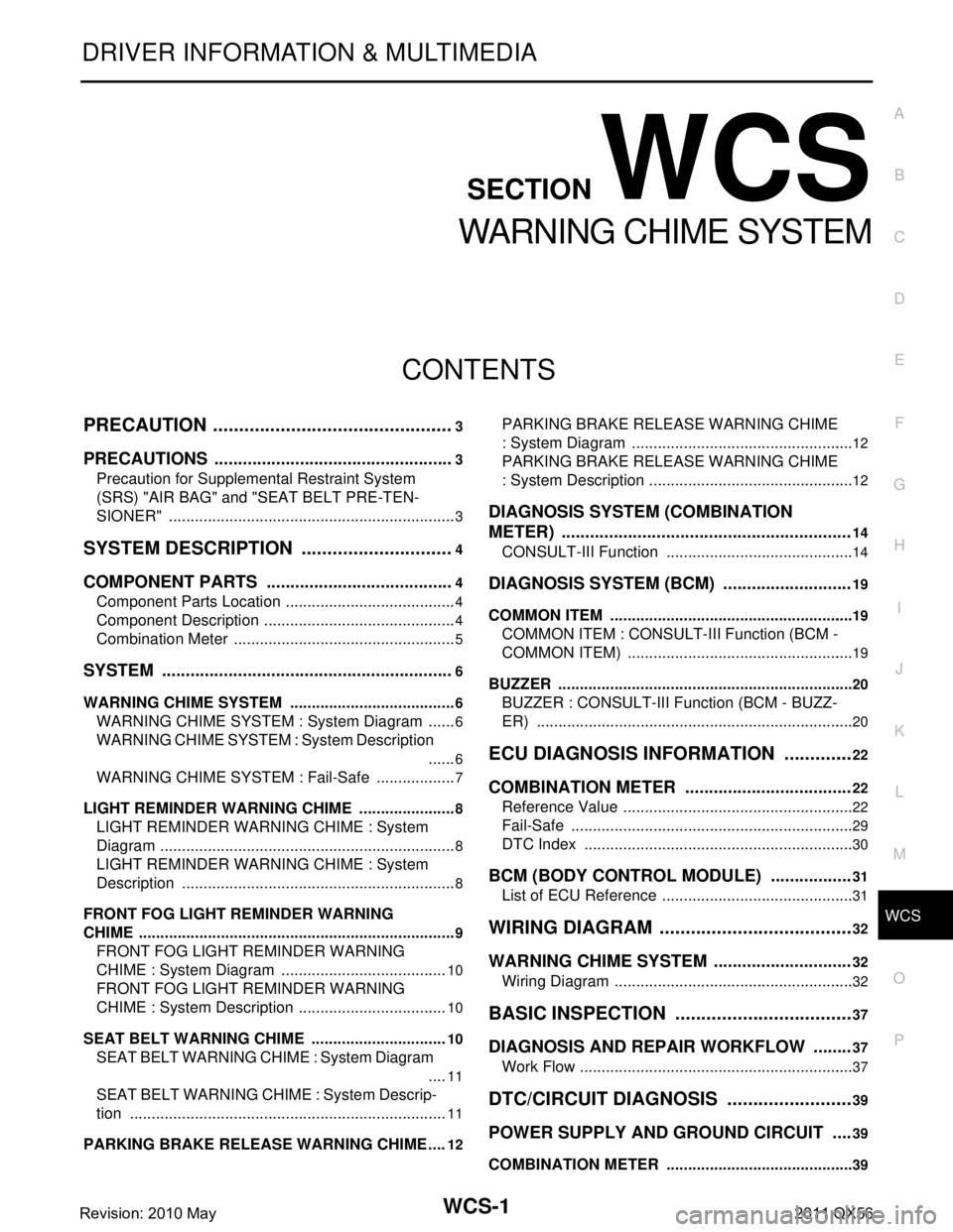
WARNING CHIME SYSTEM
PRECAUTION ................ ...............................3
PRECAUTIONS .............................................. .....3
Precaution for Supplemental Restraint System
(SRS) "AIR BAG" and "SEAT BELT PRE-TEN-
SIONER" ............................................................. ......
3
SYSTEM DESCRIPTION ..............................4
COMPONENT PARTS ................................... .....4
Component Parts Location .................................. ......4
Component Description .............................................4
Combination Meter ....................................................5
SYSTEM ..............................................................6
WARNING CHIME SYSTEM .......................................6
WARNING CHIME SYSTEM : System Diagram . ......6
WARNING CHIME SYSTEM : System Description
......
6
WARNING CHIME SYSTEM : Fail-Safe ...................7
LIGHT REMINDER WARNING CHIME ................. ......8
LIGHT REMINDER WARNING CHIME : System
Diagram .....................................................................
8
LIGHT REMINDER WARNING CHIME : System
Description ................................................................
8
FRONT FOG LIGHT REMINDER WARNING
CHIME .................................................................... ......
9
FRONT FOG LIGHT REMINDER WARNING
CHIME : System Diagram .......................................
10
FRONT FOG LIGHT REMINDER WARNING
CHIME : System Description ...................................
10
SEAT BELT WARNING CHIME ............................ ....10
SEAT BELT WARNING CHIME : System Diagram
....
11
SEAT BELT WARNING CHIME : System Descrip-
tion ...................................................................... ....
11
PARKING BRAKE RELEASE WARNING CHIME ....12
PARKING BRAKE RELEASE WARNING CHIME
: System Diagram ................................................ ....
12
PARKING BRAKE RELEASE WARNING CHIME
: System Description ................................................
12
DIAGNOSIS SYSTEM (COMBINATION
METER) .............................................................
14
CONSULT-III Function ............................................14
DIAGNOSIS SYSTEM (BCM) ...........................19
COMMON ITEM ..................................................... ....19
COMMON ITEM : CONSULT-III Function (BCM -
COMMON ITEM) .....................................................
19
BUZZER ................................................................. ....20
BUZZER : CONSULT-III Function (BCM - BUZZ-
ER) ..........................................................................
20
ECU DIAGNOSIS INFORMATION ..............22
COMBINATION METER ...................................22
Reference Value .................................................. ....22
Fail-Safe ..................................................................29
DTC Index ...............................................................30
BCM (BODY CONTROL MODULE) .................31
List of ECU Reference .............................................31
WIRING DIAGRAM ......................................32
WARNING CHIME SYSTEM .............................32
Wiring Diagram .................................................... ....32
BASIC INSPECTION ...................................37
DIAGNOSIS AND REPAIR WORKFLOW ........37
Work Flow ............................................................ ....37
DTC/CIRCUIT DIAGNOSIS .........................39
POWER SUPPLY AND GROUND CIRCUIT ....39
COMBINATION METER ........................................ ....39
Revision: 2010 May2011 QX56
Page 5406 of 5598

WCS-2
COMBINATION METER : Diagnosis Procedure ....39
METER BUZZER CIRCUIT ................................40
Component Function Check ................................ ...40
Diagnosis Procedure .............................................40
SEAT BELT BUCKLE SWITCH SIGNAL CIR-
CUIT ...................................................................
41
Component Function Check .............................. ...41
Diagnosis Procedure .............................................41
Component Inspection ............................................42
PARKING BRAKE SWITCH SIGNAL CIR-
CUIT ...................................................................
43
Diagnosis Procedure ........................................... ...43
Component Inspection ............................................43
SYMPTOM DIAGNOSIS ............................44
THE LIGHT REMINDER WARNING DOES
NOT SOUND ................................................... ...
44
Description ........................................................... ...44
Diagnosis Procedure ...............................................44
THE SEAT BELT WARNING CONTINUES
SOUNDING, OR DOES NOT SOUND ...............
45
Description ........................................................... ...45
Diagnosis Procedure ...............................................45
THE PARKING BRAKE RELEASE WARNING
CONTINUES SOUNDING, OR DOES NOT
SOUND ..............................................................
46
Description ........................................................... ...46
Diagnosis Procedure ...............................................46
Revision: 2010 May2011 QX56
Page 5412 of 5598

WCS-8
< SYSTEM DESCRIPTION >
SYSTEM
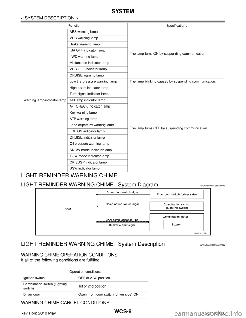
LIGHT REMINDER WARNING CHIME
LIGHT REMINDER WARNING CHIME : System DiagramINFOID:0000000006222543
LIGHT REMINDER WARNING CHIME : System DescriptionINFOID:0000000006222544
WARNING CHIME OPERATION CONDITIONS
If all of the following conditions are fulfilled.
WARNING CHIME CANCEL CONDITIONS
Warning lamp/indicator lampABS warning lamp
The lamp turns ON by suspending communication.
VDC warning lamp
Brake warning lamp
IBA OFF indicator lamp
4WD warning lamp
Malfunction indicator lamp
VDC OFF indicator lamp
CRUISE warning lamp
Low tire pressure warning lamp The lamp blinking caused by suspending communication.
High beam indicator lamp
The lamp turns OFF by suspending communication.
Turn signal indicator lamp
Tail lamp indicator lamp
A/T CHECK indicator lamp
Key warning lamp
ATP warning lamp
Lane departure warning lamp
LDP ON indicator lamp
CRUISE indicator lamp
Oil pressure warning lamp
SNOW mode indicator lamp
TOW mode indicator lamp
CK SUSP indicator lamp
BSW indicator lamp
Function Specifications
JSNIA2421GB
Operation conditions
Ignition switch OFF or ACC position
Combination switch (Lighting
switch) 1st or 2nd position
Driver door Open [front door switch (driver side) ON]
Revision: 2010 May2011 QX56
Page 5418 of 5598

WCS-14
< SYSTEM DESCRIPTION >
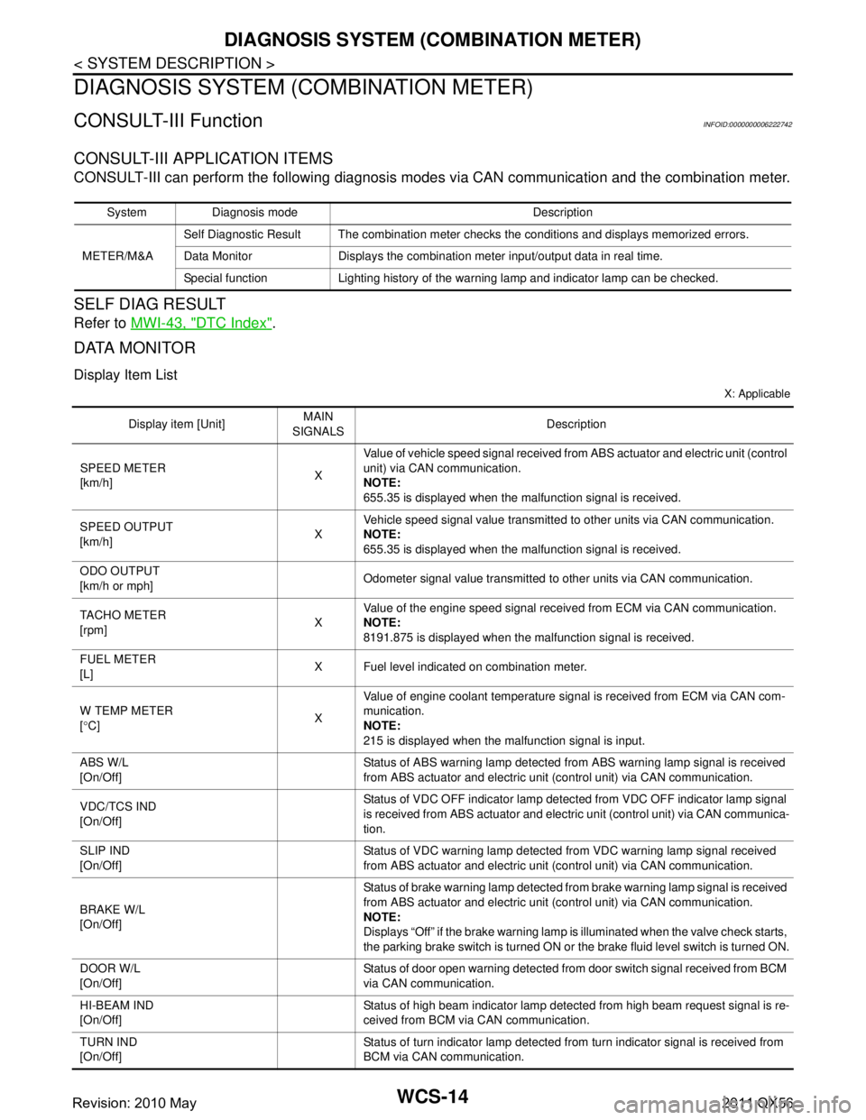
DIAGNOSIS SYSTEM (COMBINATION METER)
DIAGNOSIS SYSTEM (COMBINATION METER)
CONSULT-III FunctionINFOID:0000000006222742
CONSULT-III APPLICATION ITEMS
CONSULT-III can perform the following diagnosis modes via CAN communication and the combination meter.
SELF DIAG RESULT
Refer to MWI-43, "DTC Index".
DATA MONITOR
Display Item List
X: Applicable
System Diagnosis mode Description
METER/M&A Self Diagnostic Result The combination meter checks the conditions and displays memorized errors.
Data Monitor Displays the combination meter input/output data in real time.
Special function Lighting history of the warning lamp and indicator lamp can be checked.
Display item [Unit]
MAIN
SIGNALS Description
SPEED METER
[km/h] XValue of vehicle speed
signal received from ABS actuator and el ectric unit (control
unit) via CAN communication.
NOTE:
655.35 is displayed when the malfunction signal is received.
SPEED OUTPUT
[km/h] XVehicle speed signal value transmitted to other units via CAN communication.
NOTE:
655.35 is displayed when the malfunction signal is received.
ODO OUTPUT
[km/h or mph] Odometer signal value transmitted to other units via CAN communication.
TACHO METER
[rpm] XValue of the engine speed signal received from ECM via CAN communication.
NOTE:
8191.875 is displayed when the malfunction signal is received.
FUEL METER
[L] X Fuel level indicated on combination meter.
W TEMP METER
[ ° C] XValue of engine coolant temperature signal is received from ECM via CAN com-
munication.
NOTE:
215 is displayed when the malfunction signal is input.
ABS W/L
[On/Off] Status of ABS warning lamp
detected from ABS warning lamp signal is received
from ABS actuator and electric unit (control unit) via CAN communication.
VDC/TCS IND
[On/Off] Status of VDC OFF indicator lamp detected from VDC OFF indicator lamp signal
is received from ABS actuator and electric
unit (control unit) via CAN communica-
tion.
SLIP IND
[On/Off] Status of VDC warning lamp detected from VDC warning lamp signal received
from ABS actuator and electric unit (control unit) via CAN communication.
BRAKE W/L
[On/Off] Status of brake warning lamp detected from brake warning lamp signal is received
from ABS actuator and electric unit (control unit) via CAN communication.
NOTE:
Displays “Off” if the brake warning lamp is illuminated when the valve check starts,
the parking brake switch is turned ON or the brake fluid level switch is turned ON.
DOOR W/L
[On/Off] Status of door open warning detected from door switch signal received from BCM
via CAN communication.
HI-BEAM IND
[On/Off] Status of high beam indicator lamp detected from high beam request signal is re-
ceived from BCM via CAN communication.
TURN IND
[On/Off] Status of turn indicator lamp detected from turn indicator signal is received from
BCM via CAN communication.
Revision: 2010 May2011 QX56
Page 5421 of 5598

WCS
DIAGNOSIS SYSTEM (COMBINATION METER)
WCS-17
< SYSTEM DESCRIPTION >
C
D E
F
G H
I
J
K L
M B A
O P
*: DDS (hill descent control) NOTE:
Some items are not available according to vehicle specification.
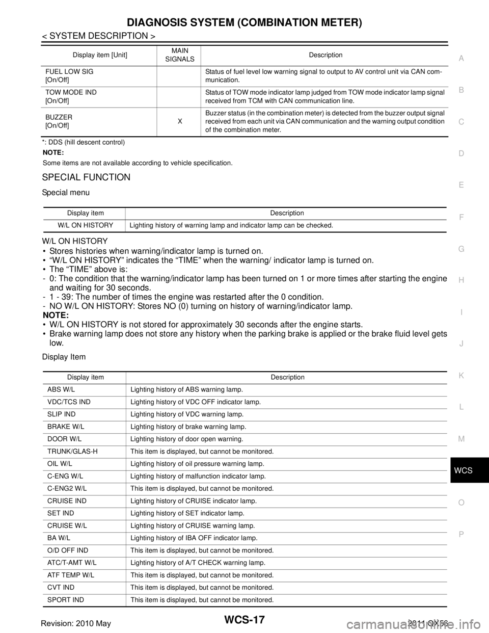
SPECIAL FUNCTION
Special menu
W/L ON HISTORY
Stores histories when warning/indicator lamp is turned on.
“W/L ON HISTORY” indicates the “TIME” when the warning/ indicator lamp is turned on.
The “TIME” above is:
- 0: The condition that the warning/indicator lamp has been turned on 1 or more times after starting the engine and waiting for 30 seconds.
- 1 - 39: The number of times the engine was restarted after the 0 condition.
- NO W/L ON HISTORY: Stores NO (0) turning on history of warning/indicator lamp.
NOTE:
W/L ON HISTORY is not stored for approximately 30 seconds after the engine starts.
Brake warning lamp does not store any history when the parking brake is applied or the brake fluid level gets
low.
Display Item
FUEL LOW SIG
[On/Off] Status of fuel level low warning signal to output to AV control unit via CAN com-
munication.
TOW MODE IND
[On/Off] Status of TOW mode indicator lamp judged from TOW mode indicator lamp signal
received from TCM with CAN communication line.
BUZZER
[On/Off] XBuzzer status (in the combination meter) is detected from the buzzer output signal
received from each unit via CAN communication and the warning output condition
of the combination meter.
Display item [Unit]
MAIN
SIGNALS Description
Display item Description
W/L ON HISTORY Lighting history of warning lamp and indicator lamp can be checked.
Display item Description
ABS W/L Lighting history of ABS warning lamp.
VDC/TCS IND Lighting history of VDC OFF indicator lamp.
SLIP IND Lighting history of VDC warning lamp.
BRAKE W/L Lighting history of brake warning lamp.
DOOR W/L Lighting history of door open warning.
TRUNK/GLAS-H This item is displayed, but cannot be monitored.
OIL W/L Lighting history of oil pressure warning lamp.
C-ENG W/L Lighting history of malfunction indicator lamp.
C-ENG2 W/L This item is displayed, but cannot be monitored.
CRUISE IND Lighting history of CRUISE indicator lamp.
SET IND Lighting history of SET indicator lamp.
CRUISE W/L Lighting histor y of CRUISE warning lamp.
BA W/L Lighting history of IBA OFF indicator lamp.
O/D OFF IND This item is displayed, but cannot be monitored.
ATC/T-AMT W/L Lighting history of A/T CHECK warning lamp.
ATF TEMP W/L This item is displayed, but cannot be monitored.
CVT IND This item is displayed, but cannot be monitored.
SPORT IND This item is displayed, but cannot be monitored.
Revision: 2010 May2011 QX56
Page 5422 of 5598

WCS-18
< SYSTEM DESCRIPTION >
DIAGNOSIS SYSTEM (COMBINATION METER)
4WD W/L Lighting history of 4WD warning lamp.
FUEL W/L Lighting history of low fuel level warning.
WASHER W/L Lighting history of low washer fluid warning.
AIR PRES W/L Lighting history of low tire pressure warning lamp.
KEY G/Y W/L Lighting history of KEY warning lamp.
KEY R W/L This item is displayed, but cannot be monitored.
KEY KNOB W/L This item is displa yed, but cannot be monitored.
EPS W/L This item is displayed, but cannot be monitored.
e-4WD This item is displayed, but cannot be monitored.
AFS OFF IND This item is displayed, but cannot be monitored.
4WAS/RAS W/L This item is displayed, but cannot be monitored.
HDC W/L This item is displayed, but cannot be monitored.
SYS FAIL W/L This item is displa yed, but cannot be monitored.
SFT POSI W/L This item is displayed, but cannot be monitored.
HV BAT W/L This item is displayed, but cannot be monitored.
HEV BRAKE W/L This item is displayed, but cannot be monitored.
SFT OPER W/L This item is displayed, but cannot be monitored.
LANE W/L Lighting history of lane departure warning lamp.
CHAGE W/L This item is displayed, but cannot be monitored.
OIL LEV LOW This item is displayed, but cannot be monitored.
DPF W/L This item is displayed, but cannot be monitored.
TRAILER IND This item is displayed, but cannot be monitored.
RUN FLAT W/L This item is displa yed, but cannot be monitored.
E-SUS W/L This item is displayed, but cannot be monitored.
LAUNCH CNT W/L This item is displayed, but cannot be monitored.
BRAKE PAD W/L This item is displa yed, but cannot be monitored.
Display item Description
Revision: 2010 May2011 QX56