2011 INFINITI QX56 turn signal
[x] Cancel search: turn signalPage 5527 of 5598

WW-8
< SYSTEM DESCRIPTION >
SYSTEM
FRONT WIPER AUTO OPERATION
Rain Detection
Rain level and sensor conditions are detected by light & rain sensor.
BCM transmits the vehicle conditions (vehicle speed, front wiper condition, rain sensor sensitivity setting,
etc.) to the light & rain sensor via the rain sensor serial link.
Light & rain sensor judges a wiping speed for front wi per by rain condition and the vehicle conditions. And it
transmits the wiping speed request signal to t he BCM via the rain sensor serial link.
Auto Wiping Operation
BCM receives the wiping speed request signal from the light & rain sensor via the rain sensor serial link.
BCM controls front wiper operation according to t he wiping speed request signals. And it transmits the front
wiper request signals (LO or HI) to the IPDM E/R via CAN communication line.
Front wiper AUTO operating condition
- Ignition switch ON
- Front wiper switch AUTO
NOTE:
When the front wiper switch is turned to AUTO positi on, front wiper operates once regardless of rainy condi-
tions.
Rain Sensor Sensitivity Setting
BCM determines rain sensor sensitivity according to wiper volume dial position.
NOTE:
When the wiper volume dial position is turned up by 1 level under front wiper AUTO operating condition, front
wiper operates once.
Splash mode operation
Front wiper is operated at HI regardl ess of the wiper volume adjustment position, when water drops are instan-
taneously sprayed over the windshield glass due to wate r splash from oncoming vehicles or other causes.
After that, AUTO operation is performed depending on the amount of water drops.
SPLASH MODE OPERATION CONDITIONS Front wiper switch AUTO
Ignition switch ON
NOTE:
Splash mode is not operated and auto wiping operati on is performed, while the vehicle is stopped.
FRONT WIPER AUTO STOP OPERATION
BCM stops transmitting the front wiper request signal when the front wiper switch is turned OFF.
IPDM E/R detects the front wiper stop position signal from the front wiper motor and detects the front wiper
motor position (stop position/except stop position).
Wiper volume dial position Sensitivity
1 High sensitivity
2
3 Medium−high sensitivity
4
5 Low−medium sensitivity
6
7 Low sensitivity
Revision: 2010 May2011 QX56
Page 5528 of 5598
SYSTEMWW-9
< SYSTEM DESCRIPTION >
C
DE
F
G H
I
J
K
M A
B
WW
N
O P
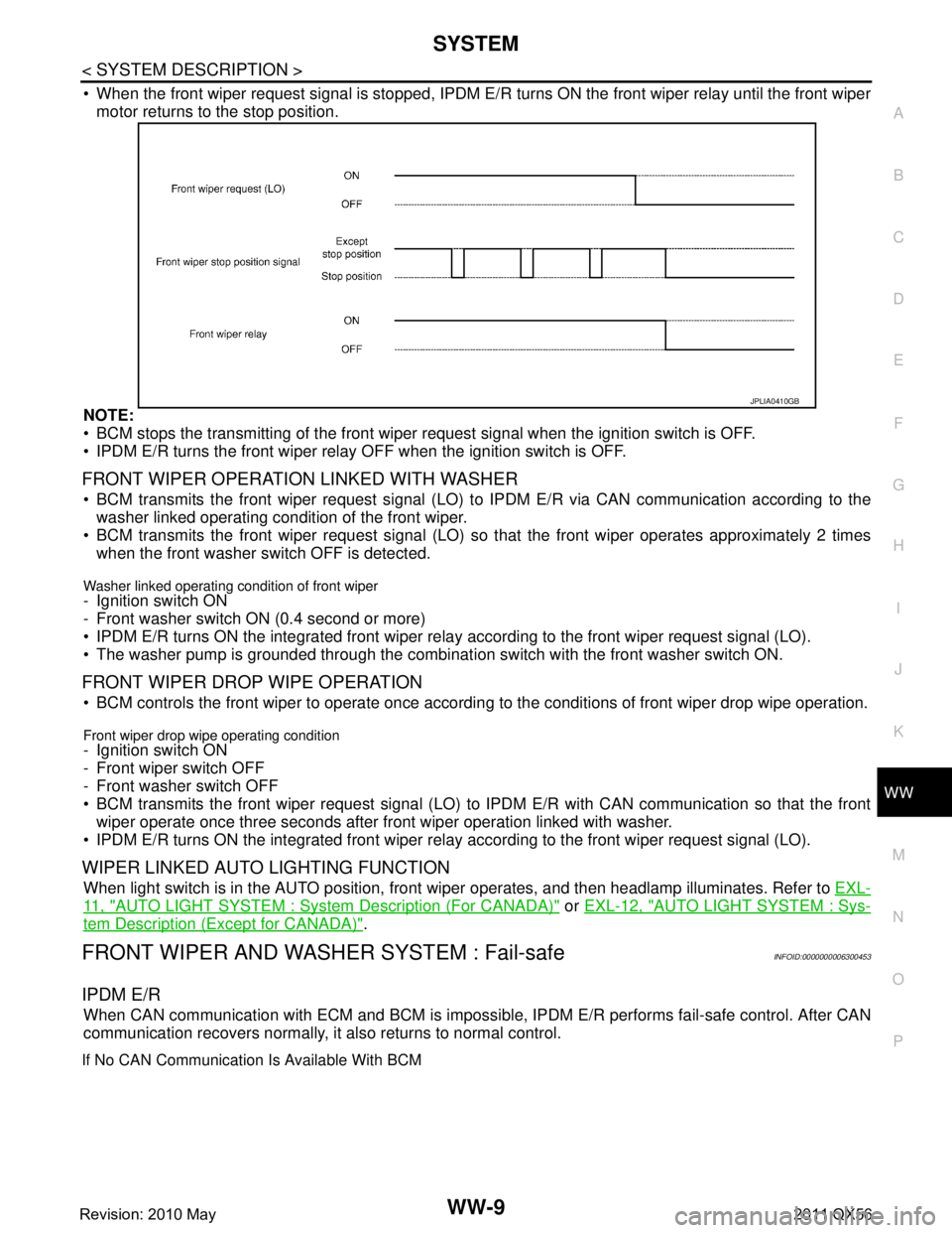
When the front wiper request signal is stopped, IPDM E/R turns ON the front wiper relay until the front wiper
motor returns to the stop position.
NOTE:
BCM stops the transmitting of the front wiper request signal when the ignition switch is OFF.
IPDM E/R turns the front wiper relay OFF when the ignition switch is OFF.
FRONT WIPER OPERATION LINKED WITH WASHER
BCM transmits the front wiper request signal (LO) to IPDM E/R via CAN communication according to the
washer linked operating condition of the front wiper.
BCM transmits the front wiper request signal (LO) so that the front wiper operates approximately 2 times
when the front washer switch OFF is detected.
Washer linked operating condition of front wiper
- Ignition switch ON
- Front washer switch ON (0.4 second or more)
IPDM E/R turns ON the integrated front wiper rela y according to the front wiper request signal (LO).
The washer pump is grounded through the combinati on switch with the front washer switch ON.
FRONT WIPER DROP WIPE OPERATION
BCM controls the front wiper to operate once according to the conditions of front wiper drop wipe operation.
Front wiper drop wipe operating condition
- Ignition switch ON
- Front wiper switch OFF
- Front washer switch OFF
BCM transmits the front wiper request signal (LO) to IPDM E/R with CAN communication so that the front
wiper operate once three seconds after fr ont wiper operation linked with washer.
IPDM E/R turns ON the integrated front wiper rela y according to the front wiper request signal (LO).
WIPER LINKED AUTO LIGHTING FUNCTION
When light switch is in the AUTO position, front wiper operates, and then headlamp illuminates. Refer to EXL-
11 , "AUTO LIGHT SYSTEM : System Description (For CANADA)" or EXL-12, "AUTO LIGHT SYSTEM : Sys-
tem Description (Except for CANADA)".
FRONT WIPER AND WASHER SYSTEM : Fail-safeINFOID:0000000006300453
IPDM E/R
When CAN communication with ECM and BCM is impossible, IPDM E/R performs fail-safe control. After CAN
communication recovers normally, it also returns to normal control.
If No CAN Communication Is Available With BCM
JPLIA0410GB
Revision: 2010 May2011 QX56
Page 5529 of 5598
WW-10
< SYSTEM DESCRIPTION >
SYSTEM
IPDM E/R detects front wiper stop position by a front wiper stop position signal.
When a front wiper stop position signal is in the conditi ons listed below, IPDM E/R stops power supply to wiper
after repeating a front wiper 10 seconds activation and 20 seconds stop five times.
NOTE:
This operation status can be confirmed on the IPDM E/ R “Data Monitor” that displays “BLOCK” for the item
“WIP PROT” while the wiper is stopped.
BCM
BCM detects the rain sensor serial link error and the light & rain sensor malfunction.
BCM controls the following fail-safe when light & rain sensor has a malfunction.
Fail-safe Control
Front wiper control
- Front wiper switch AUTO and sensing rain drop: The c ondition just before the activation of fail-safe is main-
tained until the front wiper switch is turned OFF.
- Front wiper switch AUTO and not sensing rain drop: Front wiper is LO operation until the front wiper switch is
turned off.
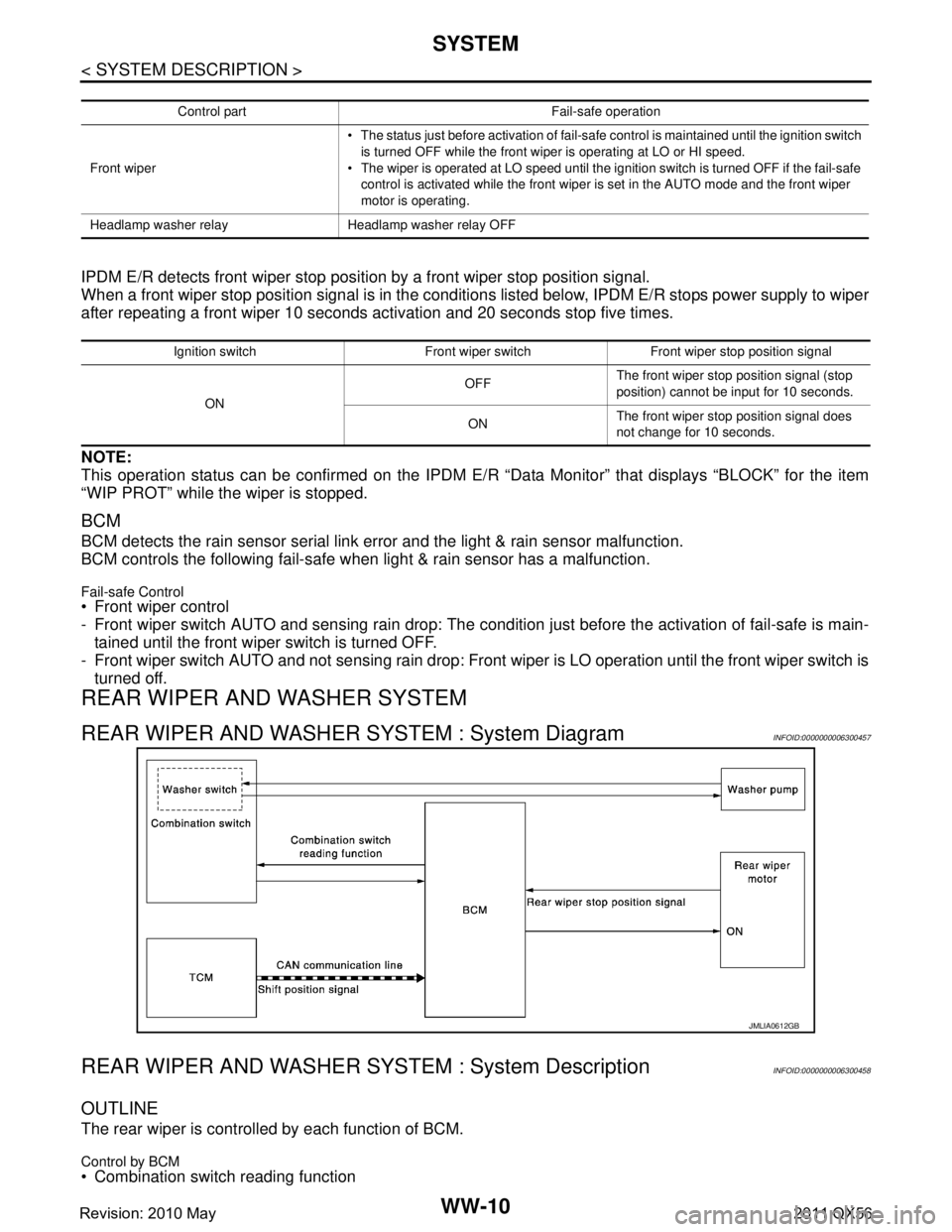
REAR WIPER AND WASHER SYSTEM
REAR WIPER AND WASHER SYSTEM : System DiagramINFOID:0000000006300457
REAR WIPER AND WASHER S YSTEM : System DescriptionINFOID:0000000006300458
OUTLINE
The rear wiper is controlled by each function of BCM.
Control by BCM
Combination switch reading function
Control part Fail-safe operation
Front wiper The status just before activation of fail-safe control is maintained until the ignition switch
is turned OFF while the front wiper is operating at LO or HI speed.
The wiper is operated at LO speed until the ignition switch is turned OFF if the fail-safe
control is activated while the front wiper is set in the AUTO mode and the front wiper
motor is operating.
Headlamp washer relay Headlamp washer relay OFF
Ignition switch Front wiper switch Front wiper stop position signal
ON OFF
The front wiper stop position signal (stop
position) cannot be input for 10 seconds.
ON The front wiper stop position signal does
not change for 10 seconds.
JMLIA0612GB
Revision: 2010 May2011 QX56
Page 5530 of 5598
SYSTEMWW-11
< SYSTEM DESCRIPTION >
C
DE
F
G H
I
J
K
M A
B
WW
N
O P
Rear wiper control function
REAR WIPER BASIC OPERATION
BCM detects the combination switch conditi on by the combination switch reading function.
BCM controls the rear wiper to start or stop.
REAR WIPER ON OPERATION
BCM supplies power to the rear wiper motor according to the rear wiper ON operating condition.
Rear wiper ON operating condition
- Ignition switch ON
- Rear wiper switch ON
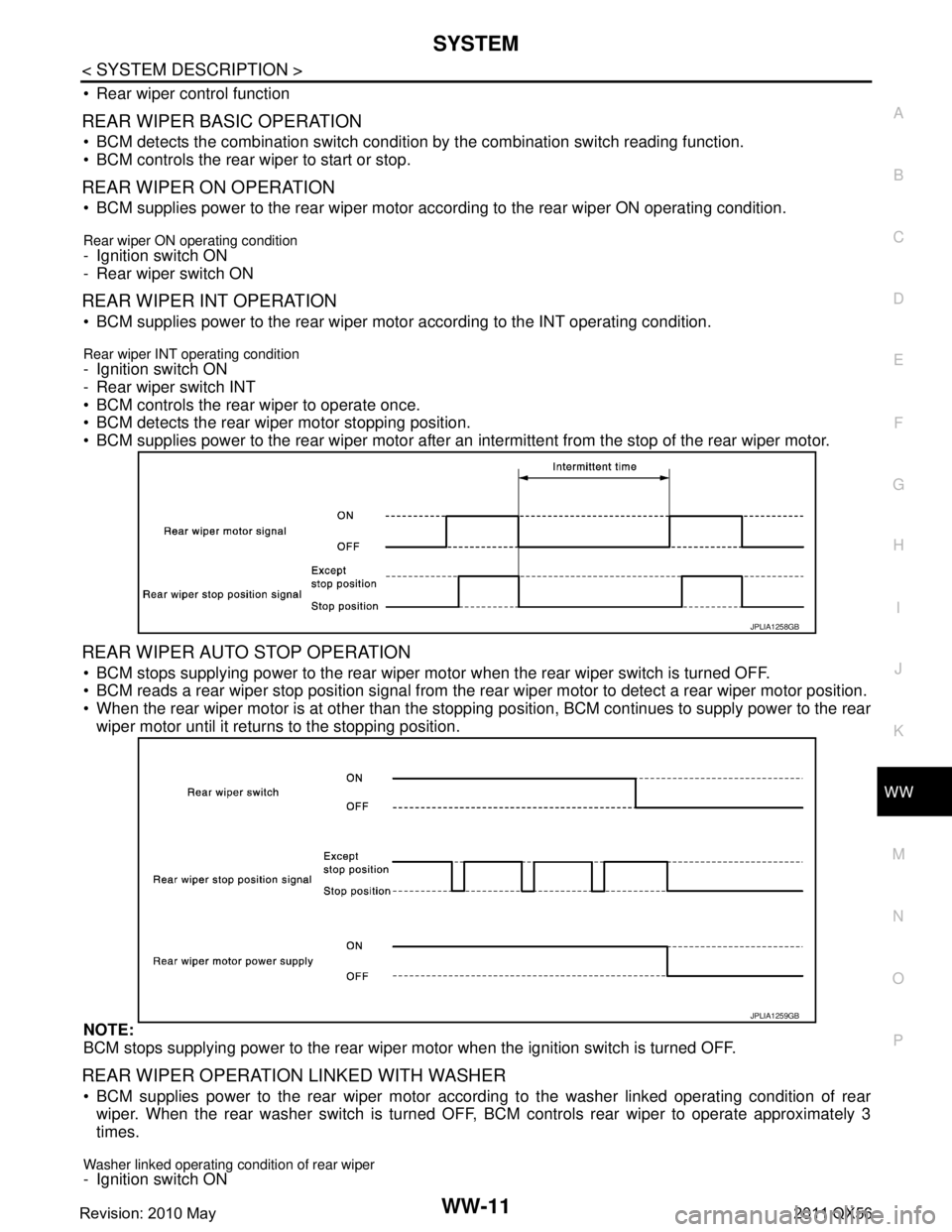
REAR WIPER INT OPERATION
BCM supplies power to the rear wiper motor according to the INT operating condition.
Rear wiper INT operating condition- Ignition switch ON
- Rear wiper switch INT
BCM controls the rear wiper to operate once.
BCM detects the rear wiper motor stopping position.
BCM supplies power to the rear wiper motor after an intermittent from the stop of the rear wiper motor.
REAR WIPER AUTO STOP OPERATION
BCM stops supplying power to the rear wiper motor when the rear wiper switch is turned OFF.
BCM reads a rear wiper stop position signal from the r ear wiper motor to detect a rear wiper motor position.
When the rear wiper motor is at other than the stopping position, BCM continues to supply power to the rear
wiper motor until it returns to the stopping position.
NOTE:
BCM stops supplying power to the rear wiper motor when the ignition switch is turned OFF.
REAR WIPER OPERATION LINKED WITH WASHER
BCM supplies power to the rear wiper motor accord ing to the washer linked operating condition of rear
wiper. When the rear washer switch is turned OFF, BCM controls rear wiper to operate approximately 3
times.
Washer linked operating condition of rear wiper- Ignition switch ON
JPLIA1258GB
JPLIA1259GB
Revision: 2010 May2011 QX56
Page 5532 of 5598
SYSTEMWW-13
< SYSTEM DESCRIPTION >
C
DE
F
G H
I
J
K
M A
B
WW
N
O P
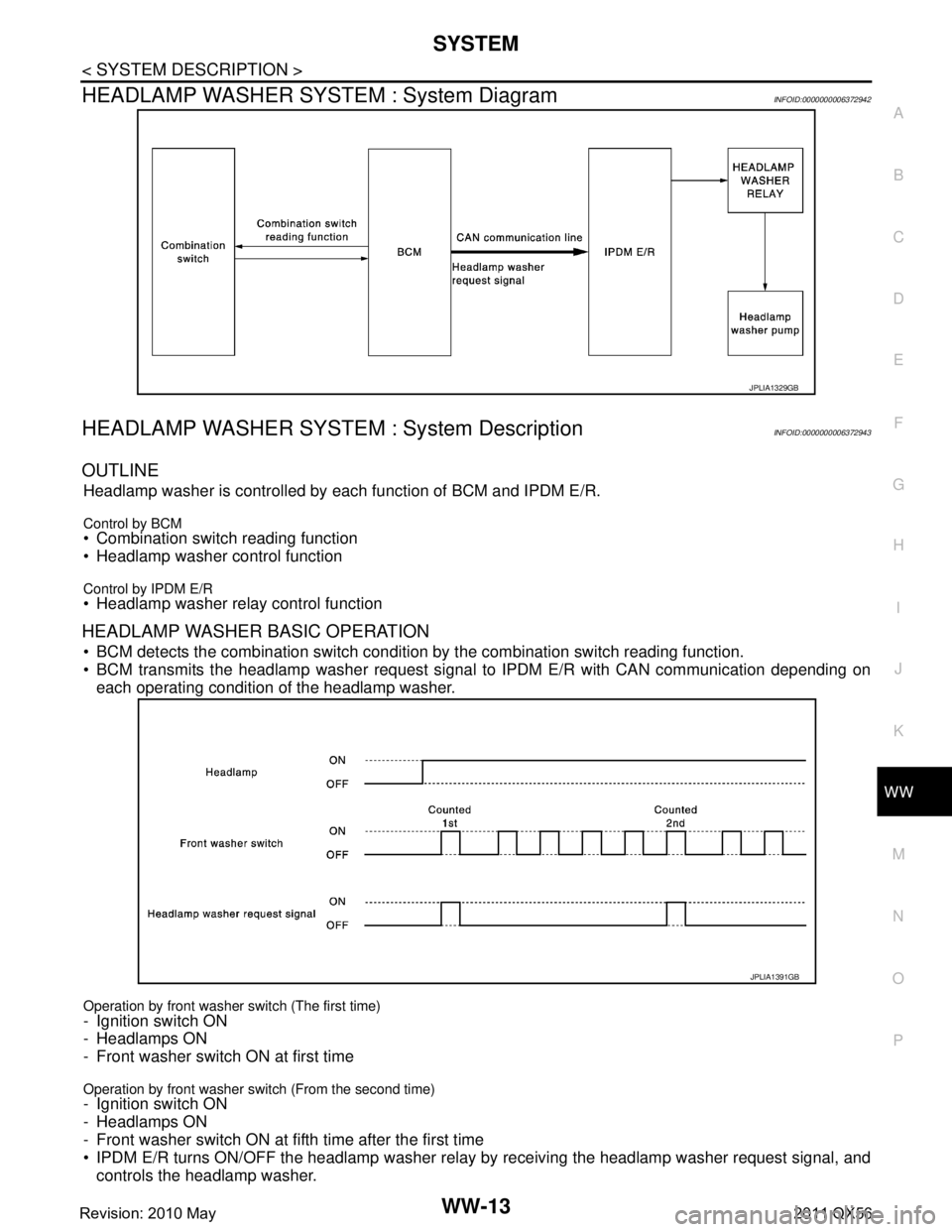
HEADLAMP WASHER SYSTEM : System DiagramINFOID:0000000006372942
HEADLAMP WASHER SYSTEM : System DescriptionINFOID:0000000006372943
OUTLINE
Headlamp washer is controlled by each function of BCM and IPDM E/R.
Control by BCM Combination switch reading function
Headlamp washer control function
Control by IPDM E/R Headlamp washer relay control function
HEADLAMP WASHER BASIC OPERATION
BCM detects the combination switch conditi on by the combination switch reading function.
BCM transmits the headlamp washer request signal to IPDM E/R with CAN communication depending on
each operating condition of the headlamp washer.
Operation by front washer switch (The first time)
- Ignition switch ON
- Headlamps ON
- Front washer switch ON at first time
Operation by front washer switch (From the second time)- Ignition switch ON
- Headlamps ON
- Front washer switch ON at fifth time after the first time
IPDM E/R turns ON/OFF the headlamp washer relay by receiving the headlamp washer request signal, and
controls the headlamp washer.
JPLIA1329GB
JPLIA1391GB
Revision: 2010 May2011 QX56
Page 5533 of 5598

WW-14
< SYSTEM DESCRIPTION >
DIAGNOSIS SYSTEM (BCM)
DIAGNOSIS SYSTEM (BCM)
COMMON ITEM
COMMON ITEM : CONSULT-III Function (BCM - COMMON ITEM)INFOID:0000000006349813
APPLICATION ITEM
CONSULT-III performs the following functions via CAN communication with BCM.
SYSTEM APPLICATION
BCM can perform the following functions for each system.
NOTE:
It can perform the diagnosis modes except the following for all sub system selection items.
×: Applicable item
*: This item is indicated, but not used.
FREEZE FRAME DATA (FFD)
The BCM records the following vehicle condition at the time a particular DTC is detected, and displays on
CONSULT-III.
Diagnosis mode Function Description
Work Support Changes the setting for each system function.
Self Diagnostic Result Displays the diagnosis results judged by BCM. Refer to BCS-57, "
DTCIndex".
CAN Diag Support Monitor Monitors the reception status of CAN communication viewed from BCM. Refer to CONSULT-III opera-
tion manual.
Data Monitor The BCM input/output signals are displayed.
Active Test The signals used to activate ea ch device are forcibly supplied from BCM.
Ecu Identification The BCM part number is displayed.
Configuration Read and save the vehicle specification.
Write the vehicle specification when replacing BCM.
System Sub system selection item Diagnosis mode
Work Support Data Monitor Active Test
Door lock DOOR LOCK ×××
Rear window defogger REAR DEFOGGER ××
Warning chime BUZZER ××
Interior room lamp timer INT LAMP ×××
Exterior lamp HEAD LAMP ×××
Wiper and washer WIPER ×××
Turn signal and hazard warning lamps FLASHER ×××
— AIR CONDITONER* ××
Intelligent Key system
Engine start system INTELLIGENT KEY
×××
Combination switch COMB SW ×
Body control system BCM ×
IVIS IMMU ×××
Interior room lamp battery saver BATTERY SAVER ×××
Back door TRUNK ×
Vehicle security system THEFT ALM ×××
RAP system RETAINED PWR ×
Signal buffer system SIGNAL BUFFER ××
Revision: 2010 May2011 QX56
Page 5537 of 5598
WW-18
< SYSTEM DESCRIPTION >
DIAGNOSIS SYSTEM (IPDM E/R)
DIAGNOSIS SYSTEM (IPDM E/R)
Diagnosis DescriptionINFOID:0000000006349814
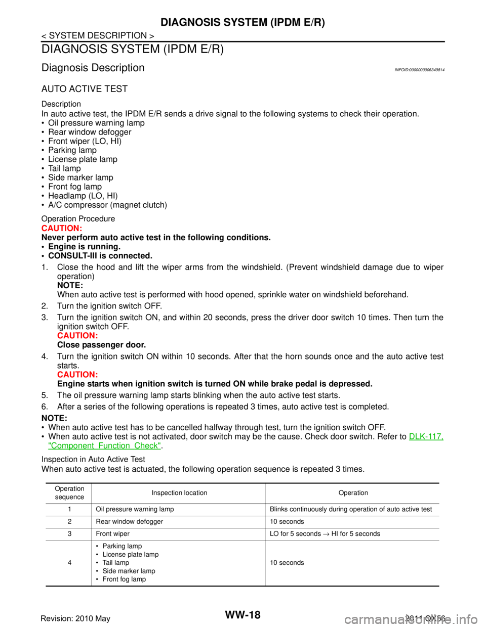
AUTO ACTIVE TEST
Description
In auto active test, the IPDM E/R sends a drive signal to the following systems to check their operation.
Oil pressure warning lamp
Rear window defogger
Front wiper (LO, HI)
Parking lamp
License plate lamp
Tail lamp
Side marker lamp
Front fog lamp
Headlamp (LO, HI)
A/C compressor (magnet clutch)
Operation Procedure
CAUTION:
Never perform auto active test in the following conditions.
Engine is running.
CONSULT-III is connected.
1. Close the hood and lift the wiper arms from the windshield. (Prevent windshield damage due to wiper
operation)
NOTE:
When auto active test is performed with hood opened, sprinkle water on windshield beforehand.
2. Turn the ignition switch OFF.
3. Turn the ignition switch ON, and within 20 seconds, pr ess the driver door switch 10 times. Then turn the
ignition switch OFF.
CAUTION:
Close passenger door.
4. Turn the ignition switch ON within 10 seconds. Af ter that the horn sounds once and the auto active test
starts.
CAUTION:
Engine starts when igniti on switch is turned ON while brake pedal is depressed.
5. The oil pressure warning lamp starts blinking when the auto active test starts.
6. After a series of the following operations is repeated 3 times, auto active test is completed.
NOTE:
When auto active test has to be cancelled halfway through test, turn the ignition switch OFF.
When auto active test is not activated, door swit ch may be the cause. Check door switch. Refer to DLK-117,
"ComponentFunctionCheck".
Inspection in Auto Active Test
When auto active test is actuated, the following operation sequence is repeated 3 times.
Operation
sequence Inspection location Operation
1 Oil pressure warning lamp Blinks continuously during operation of auto active test
2 Rear window defogger 10 seconds
3 Front wiper LO for 5 seconds → HI for 5 seconds
4 Parking lamp
License plate lamp
Tail lamp
Side marker lamp
Front fog lamp 10 seconds
Revision: 2010 May2011 QX56
Page 5557 of 5598

WW-38
< DTC/CIRCUIT DIAGNOSIS >
FRONT WIPER AUTO STOP SIGNAL CIRCUIT
FRONT WIPER AUTO STOP SIGNAL CIRCUIT
Component Function CheckINFOID:0000000006300472
1.CHECK FRONT WIPER (AUTO STOP) SIGNAL
CONSULT-III DATA MONITOR
1. Select “WIP AUTO STOP” of IPDM E/R data monitor item.
2. Operate the front wiper.
3. With the front wiper operation, check the monitor status.
Is the status of item normal?
YES >> Auto stop signal circuit is normal.
NO >> Refer to WW-38, "
Diagnosis Procedure".
Diagnosis ProcedureINFOID:0000000006300473
1.CHECK IPDM E/R OUTPUT VOLTAGE
1. Turn ignition switch OFF.
2. Disconnect front wiper motor connector.
3. Turn ignition switch ON.
4. Check voltage between front wiper motor harness connector and ground.
Is the inspection result normal?
YES >> Replace front wiper motor.
NO >> GO TO 2.
2.CHECK FRONT WIPER MOTO R (AUTO STOP) CIRCUIT
1. Turn ignition switch OFF.
2. Disconnect IPDM E/R connector.
3. Check continuity between IPDM E/R harness connector and front wiper motor harness connector.
4. Check continuity between IP DM E/R harness connector and ground.
Is the inspection result normal?
YES >> Replace IPDM E/R.
NO >> Repair or replace harness.
Monitor item Condition Monitor status
WIP AUTO STOP Front wiper motor Stop position STOP P
Except stop position ACT P
(+)
(− ) Voltage (Approx.)
Front wiper motor
Connector Terminal E42 5 Ground Battery voltage
IPDM E/R Front wiper motor Continuity
Connector Terminal Connector Terminal
E13 25 E42 5 Existed
IPDM E/R GroundContinuity
Connector Terminal
E13 25 Not existed
Revision: 2010 May2011 QX56