2011 INFINITI QX56 ground
[x] Cancel search: groundPage 4086 of 5598

PWC-1
BODY EXTERIOR, DOORS, ROOF & VEHICLE SECURITY
C
D
E
F
G H
I
J
L
M
SECTION PWC
A
B
PWC
N
O P
CONTENTS
POWER WINDOW CONTROL SYSTEM
PRECAUTION ................ ...............................4
PRECAUTIONS .............................................. .....4
Precaution for Supplemental Restraint System
(SRS) "AIR BAG" and "SEAT BELT PRE-TEN-
SIONER" ............................................................. ......
4
Precaution Necessary for Steering Wheel Rota-
tion after Battery Disconnect .....................................
4
SYSTEM DESCRIPTION ..............................6
COMPONENT PARTS ................................... .....6
Component Parts Location ................................ ......6
Component Description .............................................7
SYSTEM ..............................................................8
System Diagram ................................................. ......8
System Description ...................................................8
Fail-safe ..................................................................10
DIAGNOSIS SYSTEM (BCM) ............................11
COMMON ITEM ..................................................... ....11
COMMON ITEM : CONSULT-III Function (BCM -
COMMON ITEM) .....................................................
11
RETAIND PWR ...................................................... ....12
RETAIND PWR : CONSULT-III Function (BCM -
RETAINED PWR) ...................................................
12
ECU DIAGNOSIS INFORMATION ..............13
BCM (BODY CONTROL MODULE) ............... ....13
List of ECU Reference ........................................ ....13
POWER WINDOW MAIN SWITCH ....................14
Reference Value ................................................. ....14
Fail-safe ..................................................................15
FRONT POWER WINDOW SWITCH (PAS-
SENGER SIDE) ..................................................
16
Reference Value ................................................. ....16
Fail-safe ..................................................................17
REAR POWER WINDOW SWITCH LH ............18
Reference Value .................................................. ....18
Fail-safe ...................................................................19
REAR POWER WINDOW SWITCH RH ............20
Reference Value ......................................................20
Fail-safe ...................................................................21
WIRING DIAGRAM ......................................22
POWER WINDOW SYSTEM .............................22
Wiring Diagram .................................................... ....22
BASIC INSPECTION ...................................30
DIAGNOSIS AND REPAIR WORKFLOW ........30
Work Flow ............................................................ ....30
ADDITIONAL SERVICE WHEN REMOVING
BATTERY NEGATIVE TERMINAL ...................
31
Description ...............................................................31
Work Procedure .......................................................31
ADDITIONAL SERVICE WHEN REPLACING
CONTROL UNIT ................................................
32
Description ...............................................................32
Work Procedure .......................................................32
SYSTEM INITIALIZATION ................................33
Description ........................................................... ....33
Work Procedure .......................................................33
CHECK ANTI-PINCH FUNCTION .....................34
Description ...............................................................34
Work Procedure .......................................................34
DTC/CIRCUIT DIAGNOSIS .........................35
POWER SUPPLY AND GROUND CIRCUIT ....35
POWER WINDOW MAIN SWITCH ........................ ....35
POWER WINDOW MAIN SWITCH : Diagnosis
Procedure ................................................................
35
Revision: 2010 May2011 QX56
Page 4094 of 5598

SYSTEMPWC-9
< SYSTEM DESCRIPTION >
C
DE
F
G H
I
J
L
M A
B
PWC
N
O P
The signal mentioned below is transmitted from BCM to power window main \
switch, front power window
switch (passenger side) and rear power window switch LH/RH.
Keyless power window down signal
Door switch signal
The signal mentioned below is transmitted from power window main switch to front power window switch (pas-
senger side) and rear power window switch LH/RH.
Front passenger side door window and rear door window operation signal
Power window control by door key cylinder switch signal
Power window lock switch signal
Retained power operation signal
RETAINED POWER OPERATION
Retained power operation is an additional power supply function that enables power window system to oper-
ate during the 45 seconds even when ignition switch is turned OFF.
Retained Power Function Cancel Conditions
Front door CLOSE (door switch OFF) →OPEN (door switch ON).
When ignition switch is ON again.
When timer time passes. (45 seconds)
POWER WINDOW LOCK FUNCTION
Ground circuit inside power window main switch shuts off when power window lock switch is ON. This inhibits
power window switch operation except with the power window main switch.
ANTI-PINCH OPERATION
Anti-pinch foreign lowers door glass 150 mm (5.9 in) when foreign material is pinched in door glass during
AUTO-UP operation.
Encoder continues detecting the movement of power window motor and output the encoder pulse signal to
power window switch l while power window motor is operating.
Resistance is applied to the power window motor ro tation that changes the frequency of encoder pulse sig-
nal if foreign material is trapped in the door glass.
Power window switch controls to lower the door glass for 150 mm (5.9 in) after it detects encoder pulse sig-
nal frequency change.
Operation Condition
When all door glass AUTO-UP operation is performed ( anti-pinch function does not operate just before the
door glass closes and is fully closed)
NOTE:
Depending on environment and driving conditions, if a similar impact or load is applied to the door glass, it
may lower.
DOOR KEY CYLINDER SWITCH OPERATION
Hold the door key cylinder to the LOCK or UNLOCK direct ion for 1.5 seconds or more to OPEN or CLOSE all
power windows when ignition switch is OFF. In addition, it stops when key position is moved to NEUTRAL
when operating.
Operation Condition
Ignition switch OFF.
Hold door key cylinder to LOCK position for 1.5 se conds or more to perform CLOSE operation of the door
glass.
Hold door key cylinder to UNLOCK position for 1.5 se conds or more to perform OPEN operation of the door
glass.
KEYLESS POWER WINDOW DOWN FUNCTION
All power windows open when the unlock button on Intelligent Key is activated and kept pressed for more than
3 seconds with the ignition switch OFF. The wi ndows keep opening if the unlock button is continuously
pressed.
The power window opening stops when the following operations are performed.
When the unlock button is kept pressed more than 15 seconds.
When the ignition switch is turned ON while the power window opening is operated.
When the unlock button is released.
While retained power operation activate, keyless power window down function cannot be operated.
Revision: 2010 May2011 QX56
Page 4099 of 5598
PWC-14
< ECU DIAGNOSIS INFORMATION >
POWER WINDOW MAIN SWITCH
POWER WINDOW MAIN SWITCH
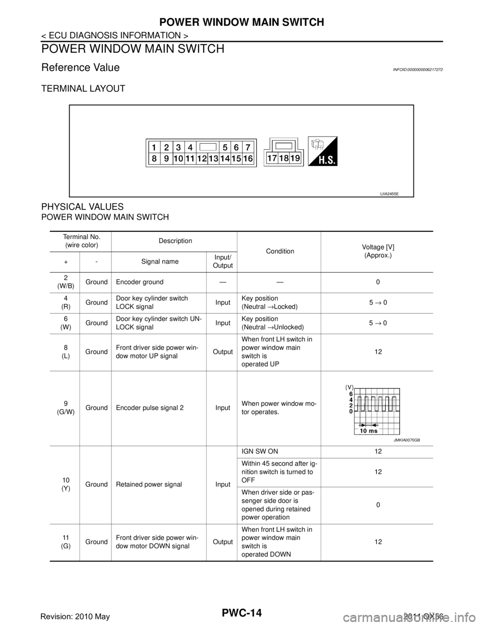
Reference Value INFOID:0000000006217272
TERMINAL LAYOUT
PHYSICAL VALUES
POWER WINDOW MAIN SWITCH
LIIA2455E
Te r m i n a l N o .(wire color) Description
ConditionVoltage [V]
(Approx.)
+ - Signal name Input/
Output
2
(W/B) Ground Encoder ground — — 0
4
(R) Ground Door key cylinder switch
LOCK signal
InputKey position
(Neutral
→Locked) 5
→ 0
6
(W) Ground
Door key cylinder switch UN-
LOCK signal Input
Key position
(Neutral
→Unlocked) 5
→ 0
8
(L) Ground Front driver side power win-
dow motor UP signal
OutputWhen front LH switch in
power window main
switch is
operated UP 12
9
(G/W) Ground Encoder pulse signal 2 Input When power window mo-
tor operates.
10
(Y) Ground Retained power signal Input IGN SW ON 12
Within 45 second after ig-
nition switch is turned to
OFF
12
When driver side or pas-
senger side door is
opened during retained
power operation 0
11
(G) Ground
Front driver side power win-
dow motor DOWN signal OutputWhen front LH switch in
power window main
switch is
operated DOWN 12
JMKIA0070GB
Revision: 2010 May2011 QX56
Page 4100 of 5598
POWER WINDOW MAIN SWITCHPWC-15
< ECU DIAGNOSIS INFORMATION >
C
DE
F
G H
I
J
L
M A
B
PWC
N
O P
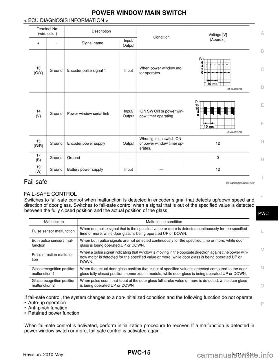
Fail-safeINFOID:0000000006217273
FAIL-SAFE CONTROL
Switches to fail-safe control when malfunction is detected in encoder signal that detects up/down speed and
direction of door glass. Switches to fail-safe control w hen a signal that is out of the specified value is detected
between the fully closed position and the actual position of the glass.
If fail-safe control, the system changes to a non-in itialized condition and the following function do not operate.
Auto-up operation
Anti-pinch function
Retained power function
When fail-safe control is activated, perform initialization procedure to recover. If a malfunction is detected in
power window switch or more, fail-safe control is activated again.
13
(G/Y) Ground Encoder pulse signal 1 Input When power window mo-
tor operates.
14
(V) Ground Power window serial link Input/
Output IGN SW ON or power win-
dow timer operating.
15
(G/R) Ground Encoder power supply Output When ignition switch ON
or power window timer op-
erates.12
17
(B) Ground Ground — — 0
19
(W) Ground Battery power supply Input — 12
Te r m i n a l N o .
(wire color) Description
ConditionVoltage [V]
(Approx.)
+ - Signal name Input/
Output
JMKIA0070GB
JPMIA0013GB
Malfunction Malfunction condition
Pulse sensor malfunction When one pulse signal that is the specified value or more is detected continuously for the specified
time or more, while door glass is being operated UP or DOWN.
Both pulse sensors mal-
function When both pulse signals are not detected continuously for the specified time or more, while door
glass is being operated UP or DOWN.
Pulse direction malfunc-
tion When a pulse signal indicating that window is moving in the opposite direction against the power win-
dow motor is detected for the specified value or more, while door glass is being operated UP or
DOWN.
Glass recognition position
malfunction 1 When the actual door glass position that is out of specified value is detected compared to the door
glass fully closed position memorized in module, while door glass is being operated UP or DOWN.
Glass recognition position
malfunction 2 When pulse count that is out of the door glass full stroke value or more is detected, while door glass
is being operated UP or DOWN.
Revision: 2010 May2011 QX56
Page 4101 of 5598
PWC-16
< ECU DIAGNOSIS INFORMATION >
FRONT POWER WINDOW SWITCH (PASSENGER SIDE)
FRONT POWER WINDOW SWITCH (PASSENGER SIDE)
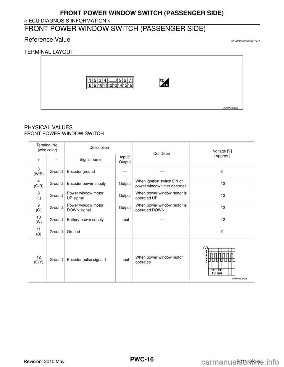
Reference Value INFOID:0000000006217274
TERMINAL LAYOUT
PHYSICAL VALUES
FRONT POWER WINDOW SWITCH
JMKIA3330ZZ
Te r m i n a l N o .(wire color) Description
ConditionVoltage [V]
(Approx.)
+ - Signal name Input/
Output
3
(W/B) Ground Encoder ground — — 0
4
(G/R) Ground Encoder power supply Output When ignition switch ON or
power window timer operates 12
8
(L) Ground Power window motor
UP signal
OutputWhen power window motor is
operated UP
12
9
(G) Ground
Power window motor
DOWN signal Output
When power window motor is
operated DOWN 12
10
(W) Ground Battery power supply Input — 12
11
(B) Ground Ground — — 0
12
(G/Y) Ground Encoder pulse signal 1 Input
When power window motor
operates
JMKIA0070GB
Revision: 2010 May2011 QX56
Page 4102 of 5598
FRONT POWER WINDOW SWITCH (PASSENGER SIDE)PWC-17
< ECU DIAGNOSIS INFORMATION >
C
DE
F
G H
I
J
L
M A
B
PWC
N
O P
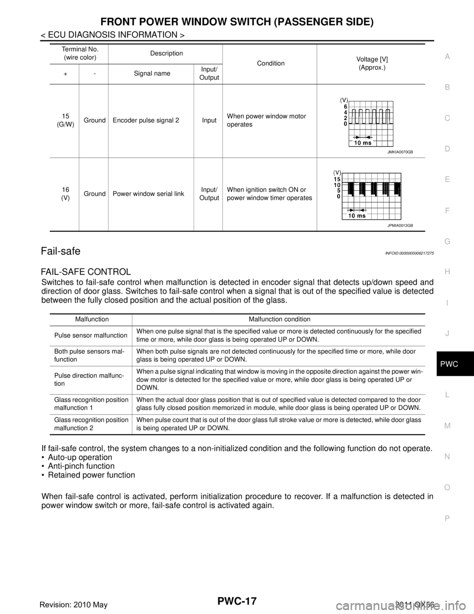
Fail-safeINFOID:0000000006217275
FAIL-SAFE CONTROL
Switches to fail-safe control when malfunction is detected in encoder signal that detects up/down speed and
direction of door glass. Switches to fail-safe control w hen a signal that is out of the specified value is detected
between the fully closed position and the actual position of the glass.
If fail-safe control, the system changes to a non-in itialized condition and the following function do not operate.
Auto-up operation
Anti-pinch function
Retained power function
When fail-safe control is activated, perform initialization procedure to recover. If a malfunction is detected in
power window switch or more, fail-safe control is activated again.
15
(G/W) Ground Encoder pulse signal 2 Input When power window motor
operates
16
(V) Ground Power window serial link Input/
Output When ignition switch ON or
power window timer operates
Te r m i n a l N o .
(wire color) Description
ConditionVoltage [V]
(Approx.)
+ - Signal name Input/
Output
JMKIA0070GB
JPMIA0013GB
Malfunction Malfunction condition
Pulse sensor malfunction When one pulse signal that is the specified value or more is detected continuously for the specified
time or more, while door glass is being operated UP or DOWN.
Both pulse sensors mal-
function When both pulse signals are not detected continuously for the specified time or more, while door
glass is being operated UP or DOWN.
Pulse direction malfunc-
tion When a pulse signal indicating that window is moving in the opposite direction against the power win-
dow motor is detected for the specified value or more, while door glass is being operated UP or
DOWN.
Glass recognition position
malfunction 1 When the actual door glass position that is out of specified value is detected compared to the door
glass fully closed position memorized in module, while door glass is being operated UP or DOWN.
Glass recognition position
malfunction 2 When pulse count that is out of the door glass full stroke value or more is detected, while door glass
is being operated UP or DOWN.
Revision: 2010 May2011 QX56
Page 4103 of 5598
PWC-18
< ECU DIAGNOSIS INFORMATION >
REAR POWER WINDOW SWITCH LH
REAR POWER WINDOW SWITCH LH
Reference Value INFOID:0000000006217276
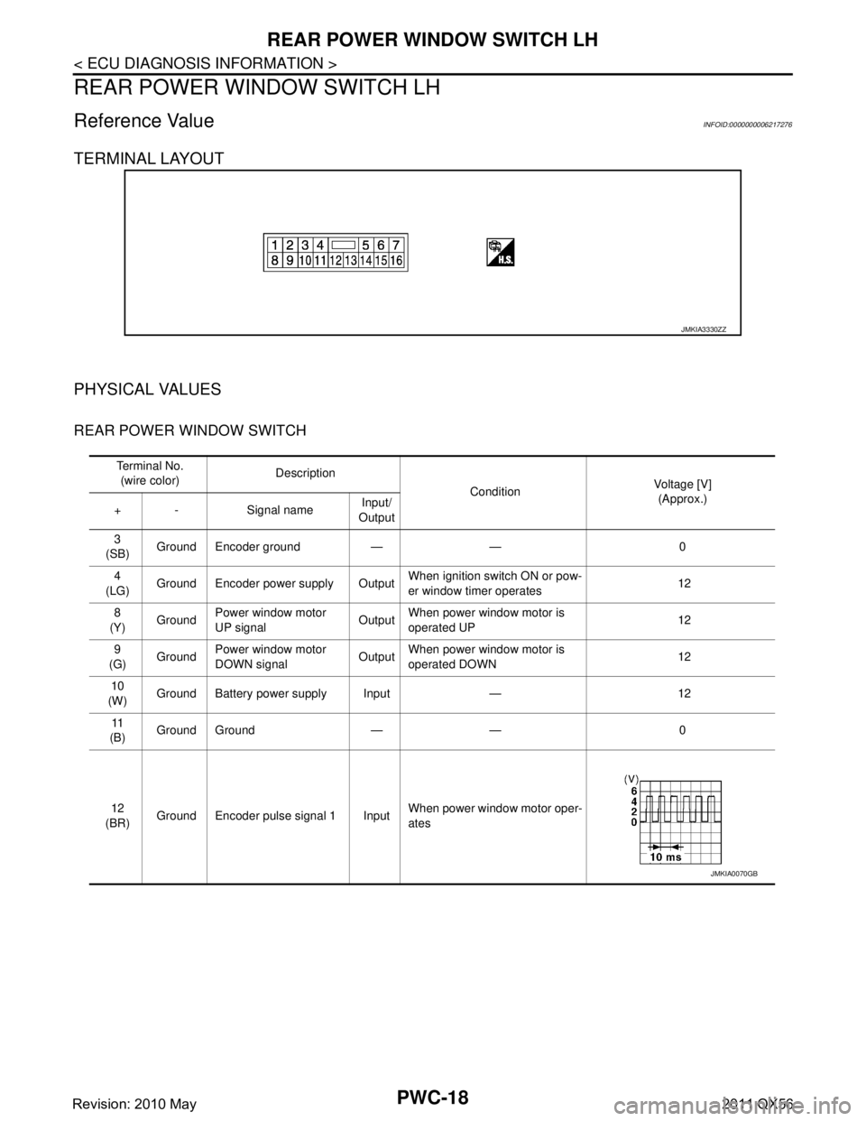
TERMINAL LAYOUT
PHYSICAL VALUES
REAR POWER WINDOW SWITCH
JMKIA3330ZZ
Te r m i n a l N o .(wire color) Description
ConditionVoltage [V]
(Approx.)
+ - Signal name Input/
Output
3
(SB) Ground Encoder ground — — 0
4
(LG) Ground Encoder power supply Output When ignition switch ON or pow-
er window timer operates
12
8
(Y) Ground
Power window motor
UP signal Output
When power window motor is
operated UP 12
9
(G) Ground Power window motor
DOWN signal OutputWhen power window motor is
operated DOWN 12
10
(W) Ground Battery power supply Input — 12
11
(B) Ground Ground — — 0
12
(BR) Ground Encoder pulse signal 1 Input When power window motor oper-
ates
JMKIA0070GB
Revision: 2010 May2011 QX56
Page 4104 of 5598
REAR POWER WINDOW SWITCH LHPWC-19
< ECU DIAGNOSIS INFORMATION >
C
DE
F
G H
I
J
L
M A
B
PWC
N
O P
Fail-safeINFOID:0000000006217277
FAIL-SAFE CONTROL
Switches to fail-safe control when malfunction is detected in encoder signal that detects up/down speed and
direction of door glass. Switches to fail-safe control w hen a signal that is out of the specified value is detected
between the fully closed position and the actual position of the glass.
If fail-safe control, the system changes to a non-in itialized condition and the following function do not operate.
Auto-up operation
Anti-pinch function
Retained power function
When fail-safe control is activated, perform initialization procedure to recover. If a malfunction is detected in
power window switch or more, fail-safe control is activated again.
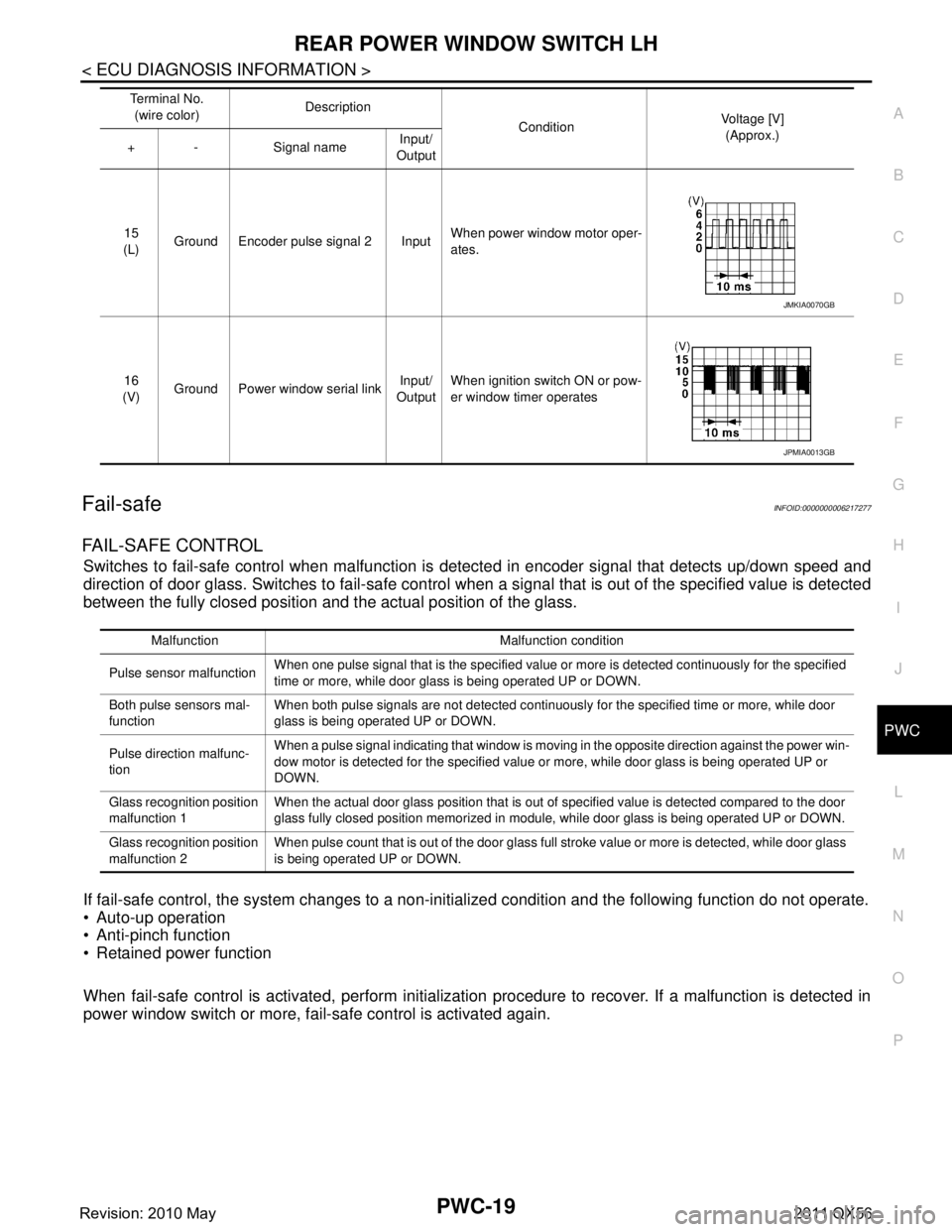
15
(L) Ground Encoder pulse signal 2 Input When power window motor oper-
ates.
16
(V) Ground Power window serial link Input/
Output When ignition switch ON or pow-
er window timer operates
Te r m i n a l N o .
(wire color) Description
ConditionVoltage [V]
(Approx.)
+ - Signal name Input/
Output
JMKIA0070GB
JPMIA0013GB
Malfunction Malfunction condition
Pulse sensor malfunction When one pulse signal that is the specified value or more is detected continuously for the specified
time or more, while door glass is being operated UP or DOWN.
Both pulse sensors mal-
function When both pulse signals are not detected continuously for the specified time or more, while door
glass is being operated UP or DOWN.
Pulse direction malfunc-
tion When a pulse signal indicating that window is moving in the opposite direction against the power win-
dow motor is detected for the specified value or more, while door glass is being operated UP or
DOWN.
Glass recognition position
malfunction 1 When the actual door glass position that is out of specified value is detected compared to the door
glass fully closed position memorized in module, while door glass is being operated UP or DOWN.
Glass recognition position
malfunction 2 When pulse count that is out of the door glass full stroke value or more is detected, while door glass
is being operated UP or DOWN.
Revision: 2010 May2011 QX56