DAS-442
< ECU DIAGNOSIS INFORMATION >[BSW]
ADAS CONTROL UNIT
C1A34 34 COMMAND ERROR ON A, B, E
CCS-119
C1A35 35 APA CIR ON A, ECCS-120
C1A36 36 APA CAN COMM CIR ON A, ECCS-121
C1A37 133 APA CAN CIR 2 ON A, B, ECCS-122
C1A38 132 APA CAN CIR 1 ON A, B, ECCS-123
C1A39 39 STRG SEN CIR ON ON ON A, B, C, D, E, G DAS-477
C1A40 40 SYSTEM SW CIRC ON C, DCCS-126
C1A2A 80 ICC SEN PWR SUP CIR ON ON A, C, D, E CCS-117
C1B00 81 CAMERA UNIT MALF ON FDAS-361
C1B01 82 CAM AIMING INCMP ON FDAS-363
C1B03 83CAM ABNRML TMP DE-
TCT BLINK F
DAS-365
C1B53 84 SIDE RDR R MALF ON G DAS-482
C1B54 85 SIDE RDR L MALF ON GDAS-483
C1F01 91 APA MOTOR MALF ON A, ECCS-129
C1F02 92 APA C/U MALF ON A, ECCS-130
C1F05 95 APA PWR SUPLY CIR ON A, ECCS-131
NO DTC IS
DETECTED.
FURTHER TESTING
MAY BE RE-
QUIRED 55
NO DTC IS DETECTED.
FURTHER TESTING
MAY BE REQUIRED ———— — —
U0121 127 VDC CAN CIR 2 ON ON ON ON A, B, C, D, E, F, G DAS-491
U0126 130 STRG SEN CAN CIR 1 ON ON ON A, B, C, D, E, GDAS-492
U0235 144 ICC SENSOR CAN
CIRC 1 ON ON A, B, C, D, E
CCS-137
U0401 120 ECM CAN CIR 1 ON ON ON A, B, E, F, G DAS-493
U0402 122 TCM CAN CIR 1 ON ON ON ON A, B, C, D, E, F, GDAS-494
U0415 126 VDC CAN CIR 1 ON ON ON ON A, B, C, D, E, F, GDAS-496
U0428 131 STRG SEN CAN CIR 2 ON ON ON A, B, C, D, E, GDAS-497
U1000NOTE100 CAN COMM CIRCUIT ON ON ON ON A, B, C, D, E, F, GDAS-486
U1010 110 CONTROL UNIT (CAN) ON ON ON ON A, B, C, D, E, F, G DAS-489
Systems for fail-safe
A: Vehicle-to-vehicle distance control mode
B: Conventional (fixed speed) cruise control mode
C: Intelligent Brake Assist (IBA)
D: Forward Collision Warning (FCW)
E: Distance Control Assist (DCA)
F: Lane Departure Warning (LDW)/Lane Departure Prevention (LDP)
G: Blind Spot Warning (BSW)
DTC
CONSULT-III display Warning lamp Fail-safe
Reference
CONSULT-III On board
display
ICC system warning lamp
IBA OFF indicator lamp
Lane departure warning lamp
BSW warning lamp
System
Revision: 2010 May2011 QX56
DAS
ADAS CONTROL UNITDAS-443
< ECU DIAGNOSIS INFORMATION > [BSW]
C
D
E
F
G H
I
J
K L
M B
N P A
NOTE:
With the detection of “U1000” some syst ems do not perform the fail-safe operation.
A system controlling based on a signal received from the control unit performs fail-safe operation when the
communication with the ADAS control unit becomes inoperable.
U1500 145 CAM CAN CIR 2 ON F DAS-381
U1501 146 CAM CAN CIR 1 ON FDAS-382
U1502 147ICC SEN CAN COMM
CIR ON ON A, B, C, D, E
CCS-152
U1503 150 SIDE RDR L CAN CIR 2 ON G DAS-502
U1504 151 SIDE RDR L CAN CIR 1 ON GDAS-503
U1505 152 SIDE RDR R CAN CIR 2 ON GDAS-504
U1506 153 SIDE RDR R CAN CIR 1 ON GDAS-505
U1507 154LOST COMM (SIDE
RDR R) ON G
DAS-506
U1508 155LOST COMM (SIDE
RDR L) ON G
DAS-507
U150B 157 ECM CAN CIRC 3 ON ON ON A, B, E, F, G DAS-498
U150C 158 VDC CAN CIRC 3 ON ON ON ON A, B, C, D, E, F, G DAS-499
U150D 159 TCM CAN CIRC 3 ON ON ON ON A, B, C, D, E, F, GDAS-500
U150E 160 BCM CAN CIRC 3 ON ON ON A, B, E, F, GDAS-501
U150F 161 AV CAN CIRC 3 DAS-61
U1512 162 HVAC CAN CIRC3 ON FDAS-383
U1513 163 METER CAN CIRC 3 ON ON ON ON A, B, C, D, E, F, GDAS-508
U1514 164 STRG SEN CAN CIRC 3 ON ON ON A, B, C, D, E, GDAS-509
U1515 165 ICC SENSOR CAN
CIRC 3 ON ON A, B, C, D, E
CCS-155
U1516 166 CAM CAN CIRC 3 ON F DAS-385
U1517 167 APA CAN CIRC 3 ON A, B, ECCS-156
U1518 168 SIDE RDR L CAN CIRC 3 ON G DAS-510
U1519 169SIDE RDR R CAN CIRC
3 ON G
DAS-511
U1520 176 4WD CAN CIRC 3 ON ON ON A, B, C, D, E, F CCS-157
Systems for fail-safe
A: Vehicle-to-vehicle distance control mode
B: Conventional (fixed speed) cruise control mode
C: Intelligent Brake Assist (IBA)
D: Forward Collision Warning (FCW)
E: Distance Control Assist (DCA)
F: Lane Departure Warning (LDW)/Lane Departure Prevention (LDP)
G: Blind Spot Warning (BSW)
DTC
CONSULT-III display Warning lamp Fail-safe
Reference
CONSULT-III On board
display
ICC system warning lamp
IBA OFF indicator lamp
Lane departure warning lamp BSW warning lamp
System
Revision: 2010 May2011 QX56
INT-30
< REMOVAL AND INSTALLATION >
HEADLINING
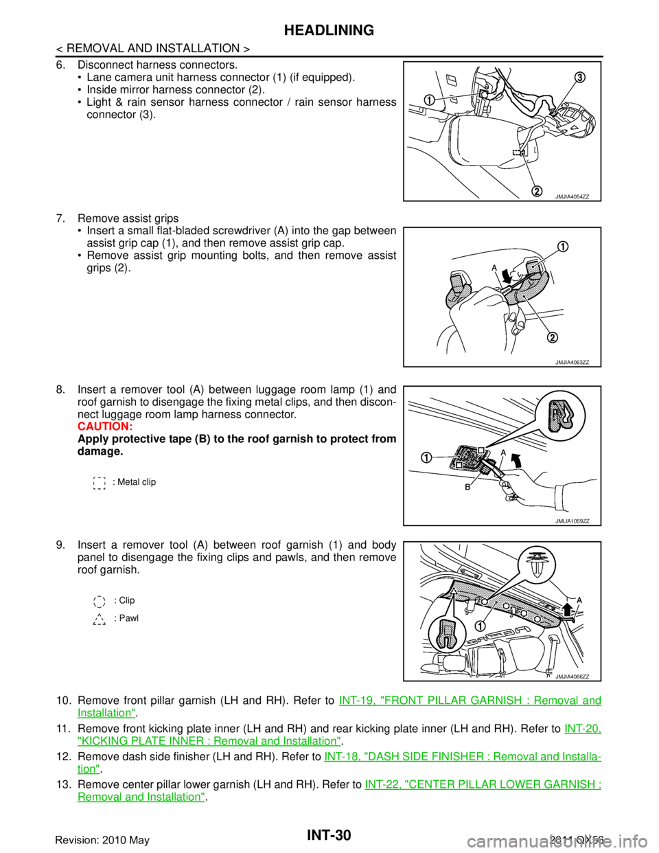
6. Disconnect harness connectors. Lane camera unit harness connector (1) (if equipped).
Inside mirror harness connector (2).
Light & rain sensor harness connector / rain sensor harness
connector (3).
7. Remove assist grips Insert a small flat-bladed screwdriver (A) into the gap between
assist grip cap (1), and then remove assist grip cap.
Remove assist grip mounting bolts, and then remove assist grips (2).
8. Insert a remover tool (A) between luggage room lamp (1) and roof garnish to disengage the fixing metal clips, and then discon-
nect luggage room lamp harness connector.
CAUTION:
Apply protective tape (B) to the roof garnish to protect from
damage.
9. Insert a remover tool (A) between roof garnish (1) and body panel to disengage the fixing clips and pawls, and then remove
roof garnish.
10. Remove front pillar garnish (LH and RH). Refer to INT-19, "
FRONT PILLAR GARNISH : Removal and
Installation".
11. Remove front kicking plate inner (LH and RH) and rear kicking plate inner (LH and RH). Refer to INT-20,
"KICKING PLATE INNER : Removal and Installation".
12. Remove dash side finisher (LH and RH). Refer to INT-18, "
DASH SIDE FINISHER : Removal and Installa-
tion".
13. Remove center pillar lower garnish (LH and RH). Refer to INT-22, "
CENTER PILLAR LOWER GARNISH :
Removal and Installation".
JMJIA4054ZZ
JMJIA4063ZZ
: Metal clip
JMLIA1059ZZ
: Clip
: Pawl
JMJIA4066ZZ
Revision: 2010 May2011 QX56
![INFINITI QX56 2011 Factory Service Manual
DAS-442
< ECU DIAGNOSIS INFORMATION >[BSW]
ADAS CONTROL UNIT
C1A34 34 COMMAND ERROR ON A, B, E
CCS-119
C1A35 35 APA CIR ON A, ECCS-120
C1A36 36 APA CAN COMM CIR ON A, ECCS-121
C1A37 133 APA CAN CIR](/manual-img/42/57033/w960_57033-1406.png "INFINITI QX56 2011 Factory Service Manual
DAS-442
< ECU DIAGNOSIS INFORMATION >[BSW]
ADAS CONTROL UNIT
C1A34 34 COMMAND ERROR ON A, B, E
CCS-119
C1A35 35 APA CIR ON A, ECCS-120
C1A36 36 APA CAN COMM CIR ON A, ECCS-121
C1A37 133 APA CAN CIR")
![INFINITI QX56 2011 Factory Service Manual
DAS
ADAS CONTROL UNITDAS-443
< ECU DIAGNOSIS INFORMATION > [BSW]
C
D
E
F
G H
I
J
K L
M B
N P A
NOTE:
With the detection of “U1000” some syst ems do not perform the fail-safe operation.
A system c](/manual-img/42/57033/w960_57033-1407.png "INFINITI QX56 2011 Factory Service Manual
DAS
ADAS CONTROL UNITDAS-443
< ECU DIAGNOSIS INFORMATION > [BSW]
C
D
E
F
G H
I
J
K L
M B
N P A
NOTE:
With the detection of “U1000” some syst ems do not perform the fail-safe operation.
A system c")