2011 INFINITI QX56 ignition
[x] Cancel search: ignitionPage 127 of 5598

ADP-118
< DTC/CIRCUIT DIAGNOSIS >
DOOR MIRROR MOTOR
DOOR MIRROR MOTOR
Component Function CheckINFOID:0000000006248414
1.CHECK DOOR MIRROR MOTOR FUNCTION
Check the operation with “MIRROR MOTOR RH” and “MI RROR MOTOR LH” in “ACTIVE TEST” mode with
CONSULT-III
Refer to ADP-22, "
CONSULT-III Function".
Is the inspection result normal?
YES >> INSPECTION END
NO >> Refer to ADP-118, "
Diagnosis Procedure".
Diagnosis ProcedureINFOID:0000000006248415
1.CHECK DOOR MIRROR MOTOR INPUT SIGNAL
1. Turn ignition switch OFF.
2. Disconnect door mirror connector.
3. Turn ignition switch ON.
4. Check voltage between door mirror harness connector and ground.
Is the inspection result normal?
YES >> GO TO 3.
NO >> GO TO 2.
2.CHECK DOOR MIRROR MOTOR CIRCUIT
1. Turn ignition switch OFF.
2. Disconnect automatic drive positioner control unit connector.
3. Check continuity between automatic drive positi oner control unit harness connector and door mirror har-
ness connector.
[driver side]
[passenger side]
4. Check continuity between automatic drive positioner control unit harness connector and ground.
(+)
(-) Condition Voltage (V)
(Approx.)
Door mirror
Connector Terminals
D3 (Driver side)
D23 (Passenger side) 12
GroundDoor mirror remote
control switch UP 12
Other than the above 0
11 LEFT 12
Other than the above 0
10 DOWN / RIGHT 12
Other than the above 0
Automatic drive positioner contro
l unit Door mirror (driver side)
Continuity
Connector Terminal Connector Terminal
M75 12
D3 10
Existed
23 12
24 11
Automatic drive positioner control unit Door mirror (passenger side) Continuity
Connector Terminal Connector Terminal
M75 22
D23 10
Existed
10 12
11 11
Revision: 2010 May2011 QX56
Page 128 of 5598
![INFINITI QX56 2011 Factory Service Manual
DOOR MIRROR MOTORADP-119
< DTC/CIRCUIT DIAGNOSIS >
C
DE
F
G H
I
K L
M A
B
ADP
N
O P
[driver side]
[passenger side]
Is the inspection result normal?
YES >> Replace automatic drive positioner control INFINITI QX56 2011 Factory Service Manual
DOOR MIRROR MOTORADP-119
< DTC/CIRCUIT DIAGNOSIS >
C
DE
F
G H
I
K L
M A
B
ADP
N
O P
[driver side]
[passenger side]
Is the inspection result normal?
YES >> Replace automatic drive positioner control](/manual-img/42/57033/w960_57033-127.png)
DOOR MIRROR MOTORADP-119
< DTC/CIRCUIT DIAGNOSIS >
C
DE
F
G H
I
K L
M A
B
ADP
N
O P
[driver side]
[passenger side]
Is the inspection result normal?
YES >> Replace automatic drive positioner control unit.
NO >> Repair or replace harness or connector.
3.CHECK DOOR MIRROR MOTOR
Check door mirror motor.
Refer to ADP-119, "
Component Inspection".
Is the inspection result normal?
YES >> Check intermittent incident.Refer to GI-40, "Intermittent Incident".
NO >> Replace door mirror.
Component InspectionINFOID:0000000006248416
1.CHECK DOOR MIRROR MOTOR 1
Check that door mirror motor does not trap foreign objects and does not have any damage.
Refer to MIR-32, "
Exploded View".
Is the inspection result normal?
YES >> GO TO 2.
NO >> Replace door mirror.
2.CHECK DOOR MIRROR MOTOR 2
1. Turn ignition switch OFF.
2. Disconnect door mirror connector.
3. Apply 12 V to each power supply terminal of door mirror motor.
Is the inspection result normal?
YES >> INSPECTION END
NO >> Replace door mirror.
Automatic drive positioner control unit
GroundContinuity
Connector Terminal
M75 12
Not existed
23
24
Automatic drive positioner control unit
GroundContinuity
Connector Terminal
M75 22
Not existed
10
11
Door mirror Operational direction
Connector Te r m i n a l
(+) (-)
D3 (Driver side)
D23 (Passenger side) 10 11 RIGHT
11 1 0 L E F T
12 10 UP
10 12 DOWN
Revision: 2010 May2011 QX56
Page 129 of 5598

ADP-120
< DTC/CIRCUIT DIAGNOSIS >
SEAT MEMORY INDICATOR
SEAT MEMORY INDICATOR
Component Function CheckINFOID:0000000006248417
1.CHECK FUNCTION
1. Select “MEMORY SW INDCTR” in “A ctive test” mode with CONSULT-III.
2. Check the memory indicator operation.
Is the operation of relevant parts normal?
YES >> INSPECTION END
NO >> Perform diagnosis procedure. Refer to ADP-120, "
DiagnosisProcedure".
Diagnosis ProcedureINFOID:0000000006248418
1.CHECK SEAT MEMORY SWITCH INDICATOR OPERATION
Check seat memory switch indicator operation.
Which is the malfunctioning indicator?
All indicators are NG>>GO TO 2.
An indicator is NG>>GO TO 4.
2.CHECK FUSE
1. Turn ignition switch OFF.
2. Check that the blown fuse after repairing the affected circuit if a fuse is blown.
Is the inspection result normal?
YES >> GO TO 3.
NO >> Replace the blown fuse after repairing the affected circuit if a fuse is blown.
3.CHECK SEAT MEMORY SWITCH INDICATOR POWER SUPPLY
Check voltage between seat memory switch harness connector and ground.
Is the inspection result normal?
YES >> Replace seat memory switch.
NO >> Repair or replace harness or connector.
4.CHECK SEAT MEMORY SW ITCH INDICATOR CIRCUIT
1. Turn ignition switch OFF.
2. Disconnect driver seat control uni t and seat memory switch connector.
3. Check continuity between driver seat control unit harness connector and seat memory switch harness
connector.
Te s t i t e m D e s c r i p t i o n
MEMORY SW INDCTR OFF
Memory switch indicatorOFF
ON-1 Indicator 1: ON
ON-2 Indicator 2: ON
Signal name Fuse No.
Battery power supply 10 (10 A)
(+) (-)Voltage (V)
(Approx.)
Seat memory switch
Connector Terminals D13 5 Ground Battery voltage
Revision: 2010 May2011 QX56
Page 154 of 5598

AV-6
< PRECAUTION >
PRECAUTIONS
PRECAUTION
PRECAUTIONS
Precaution for Supplemental Restraint System (SRS) "AIR BAG" and "SEAT BELT
PRE-TENSIONER"
INFOID:0000000006225819
The Supplemental Restraint System such as “A IR BAG” and “SEAT BELT PRE-TENSIONER”, used along
with a front seat belt, helps to reduce the risk or severi ty of injury to the driver and front passenger for certain
types of collision. This system includes seat belt switch inputs and dual stage front air bag modules. The SRS
system uses the seat belt switches to determine the front air bag deployment, and may only deploy one front
air bag, depending on the severity of a collision and w hether the front occupants are belted or unbelted.
Information necessary to service the system safely is included in the “SRS AIR BAG” and “SEAT BELT” of this
Service Manual.
WARNING:
• To avoid rendering the SRS inopera tive, which could increase the risk of personal injury or death in
the event of a collision that would result in air bag inflation, all maintenance must be performed by
an authorized NISS AN/INFINITI dealer.
Improper maintenance, including in correct removal and installation of the SRS, can lead to personal
injury caused by unintent ional activation of the system. For re moval of Spiral Cable and Air Bag
Module, see the “SRS AIR BAG”.
Do not use electrical test equipmen t on any circuit related to the SRS unless instructed to in this
Service Manual. SRS wiring harnesses can be identi fied by yellow and/or orange harnesses or har-
ness connectors.
PRECAUTIONS WHEN USING POWER TOOLS (AIR OR ELECTRIC) AND HAMMERS
WARNING:
When working near the Air Bag Diagnosis Sensor Unit or other Air Bag System sensors with the ignition ON or engine running, DO NOT use air or electric power tools or strike near the sensor(s)
with a hammer. Heavy vibration could activate the sensor(s) and deploy the air bag(s), possibly
causing serious injury.
When using air or electric power tools or hammers , always switch the ignition OFF, disconnect the
battery, and wait at least 3 minu tes before performing any service.
Precaution for Trouble DiagnosisINFOID:0000000006216211
AV COMMUNICATION SYSTEM
Do not apply voltage of 7.0 V or higher to the measurement terminals.
Use the tester with its open terminal voltage being 7.0 V or less.
Be sure to turn ignition switch OFF and disconnect the battery cable from the negative terminal before
checking the circuit.
Precaution for Harness RepairINFOID:0000000006216212
AV COMMUNICATION SYSTEM
Solder the repaired parts, and wrap with tape. [Frays of twisted line must be within 110 mm (4.33 in).]
PKIA0306E
Revision: 2010 May2011 QX56
Page 168 of 5598

AV-20
< SYSTEM DESCRIPTION >
SYSTEM
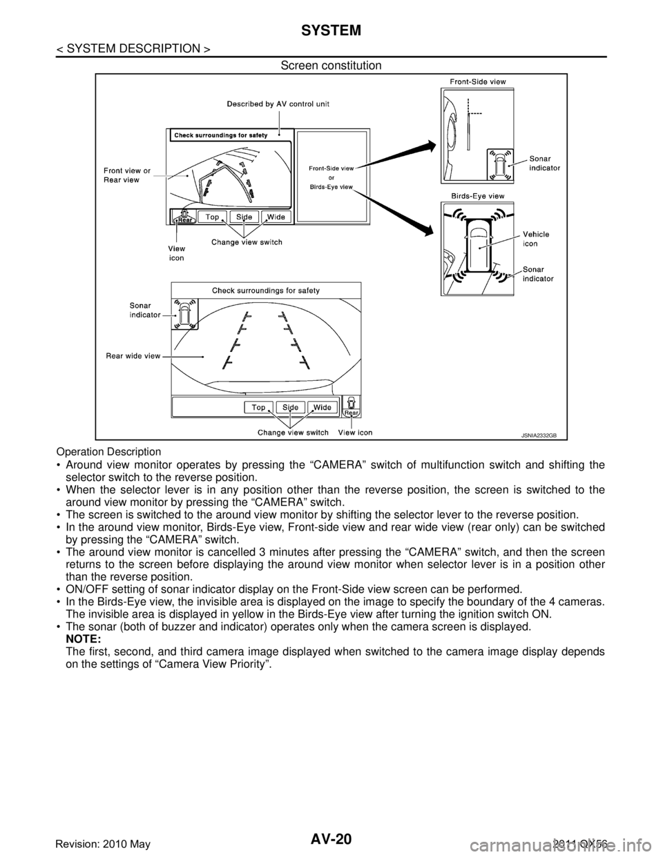
Screen constitution
Operation Description
Around view monitor operates by pressing the “CAMERA” switch of multifunction switch and shifting the
selector switch to the reverse position.
When the selector lever is in any position other t han the reverse position, the screen is switched to the
around view monitor by pressing the “CAMERA” switch.
The screen is switched to the around view monitor by sh ifting the selector lever to the reverse position.
In the around view monitor, Birds-Eye view, Front-si de view and rear wide view (rear only) can be switched
by pressing the “CAMERA” switch.
The around view monitor is cancelled 3 minutes af ter pressing the “CAMERA” switch, and then the screen
returns to the screen before displaying the around view monitor when selector lever is in a position other
than the reverse position.
ON/OFF setting of sonar indicator display on the Front-Side view screen can be performed.
In the Birds-Eye view, the invisible area is displa yed on the image to specify the boundary of the 4 cameras.
The invisible area is displayed in yellow in the Birds-Eye view after turning the ignition switch ON.
The sonar (both of buzzer and indicator) operates only when the camera screen is displayed. NOTE:
The first, second, and third camera image displayed when switched to the camera image display depends
on the settings of “Camera View Priority”.
JSNIA2332GB
Revision: 2010 May2011 QX56
Page 171 of 5598

AV
SYSTEMAV-23
< SYSTEM DESCRIPTION >
C
DE
F
G H
I
J
K L
M B A
O P
Front-side view area and guiding line
BIRDS-EYE VIEW The image from the 4 cameras is cut out and convert ed into the overhead view, and the surroundings of the
vehicle is displayed in birds-eye view.
In Birds-Eye view, the invisible area is displayed on the image to specify the boundary of the 4 cameras.
The invisible area is displayed in yellow in the Birds-Eye view after turning the ignition switch ON as an infor- mation for the user. (OFF setting can be performed)
Birds-Eye view display image
JSNIA0771GB
JSNIA3126GB
Revision: 2010 May2011 QX56
Page 176 of 5598

AV-28
< SYSTEM DESCRIPTION >
DIAGNOSIS SYSTEM (AV CONTROL UNIT)
DIAGNOSIS SYSTEM (AV CONTROL UNIT)
DescriptionINFOID:0000000006216218
The AV control unit diagnosis function starts up with multifunction switch operation and the AV control unit
performs a diagnosis for each unit in the system during the on board diagnosis.
Perform a CONSULT-III diagnosis if the on board diagnosis does not start, e.g., the screen does not display
anything, the multifunction switch does not function, etc.
On Board Diagn osis FunctionINFOID:0000000006216219
MULTIFUNCTION SWITCH AND PRESET SWITCH SELF-DIAGNOSIS FUNCTION
The ON/OFF operation (continuity) of each switch in the multifunction switch and preset switch can be
checked.
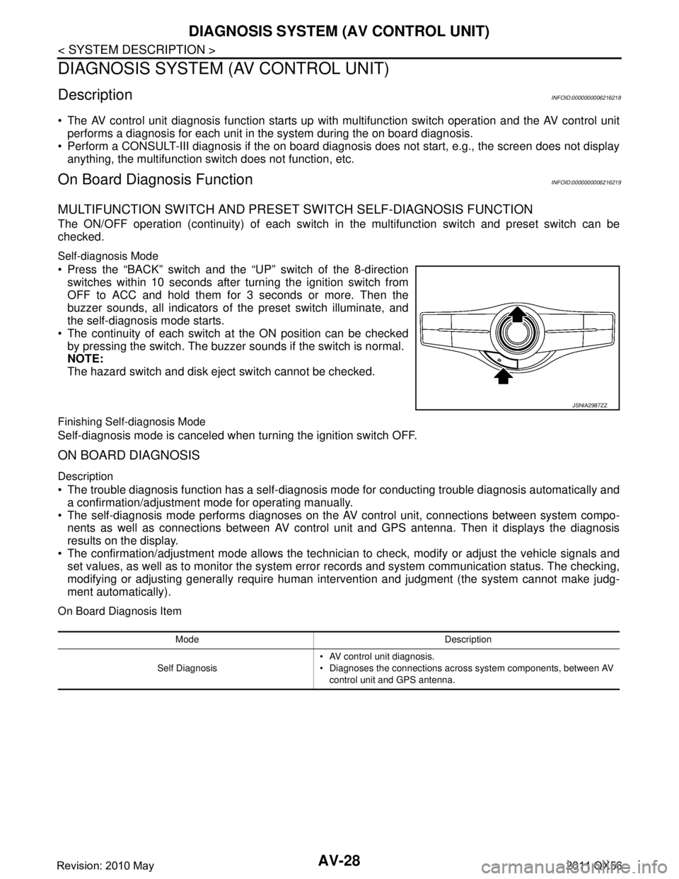
Self-diagnosis Mode
Press the “BACK” switch and the “UP” switch of the 8-direction switches within 10 seconds after turning the ignition switch from
OFF to ACC and hold them for 3 seconds or more. Then the
buzzer sounds, all indicators of the preset switch illuminate, and
the self-diagnosis mode starts.
The continuity of each switch at the ON position can be checked
by pressing the switch. The buzzer sounds if the switch is normal.
NOTE:
The hazard switch and disk eject switch cannot be checked.
Finishing Self-diagnosis Mode
Self-diagnosis mode is canceled when turning the ignition switch OFF.
ON BOARD DIAGNOSIS
Description
The trouble diagnosis function has a self-diagnosis mode for conducting trouble diagnosis automatically and
a confirmation/adjustment mode for operating manually.
The self-diagnosis mode performs diagnoses on the AV control unit, connections between system compo-
nents as well as connections between AV contro l unit and GPS antenna. Then it displays the diagnosis
results on the display.
The confirmation/adjustment mode allows the technician to check, modify or adjust the vehicle signals and
set values, as well as to monitor the system erro r records and system communication status. The checking,
modifying or adjusting generally require human inte rvention and judgment (the system cannot make judg-
ment automatically).
On Board Diagnosis Item
JSNIA2987ZZ
Mode Description
Self Diagnosis AV control unit diagnosis.
Diagnoses the connections across system components, between AV
control unit and GPS antenna.
Revision: 2010 May2011 QX56
Page 177 of 5598

AV
DIAGNOSIS SYSTEM (AV CONTROL UNIT)AV-29
< SYSTEM DESCRIPTION >
C
DE
F
G H
I
J
K L
M B A
O P
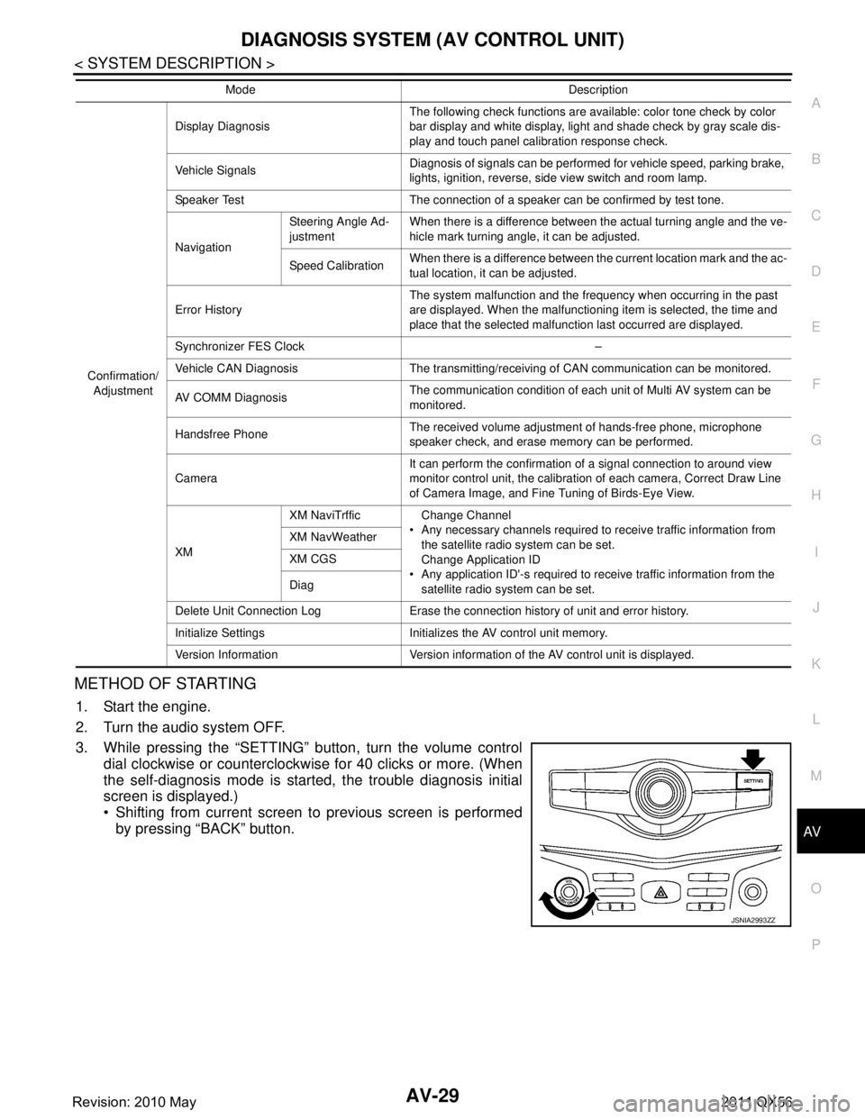
METHOD OF STARTING
1. Start the engine.
2. Turn the audio system OFF.
3. While pressing the “SETTING” button, turn the volume control dial clockwise or counterclockwise for 40 clicks or more. (When
the self-diagnosis mode is start ed, the trouble diagnosis initial
screen is displayed.)
Shifting from current screen to previous screen is performed
by pressing “BACK” button.
Confirmation/
Adjustment Display Diagnosis
The following check functions are available: color tone check by color
bar display and white display, light and shade check by gray scale dis-
play and touch panel calibration response check.
Vehicle Signals Diagnosis of signals can be performed for vehicle speed, parking brake,
lights, ignition, reverse, side view switch and room lamp.
Speaker Test The connection of a speaker can be confirmed by test tone.
Navigation Steering Angle Ad-
justment
When there is a difference between the actual turning angle and the ve-
hicle mark turning angle, it can be adjusted.
Speed Calibration When there is a difference between the current location mark and the ac-
tual location, it can be adjusted.
Error History The system malfunction and the frequency when occurring in the past
are displayed. When the malfunctioning item is selected, the time and
place that the selected malfunction last occurred are displayed.
Synchronizer FES Clock –
Vehicle CAN Diagnosis The transmitting/receiving of CAN communication can be monitored.
AV COMM Diagnosis The communication condition of each unit of Multi AV system can be
monitored.
Handsfree Phone The received volume adjustment of hands-free phone, microphone
speaker check, and erase memory can be performed.
Camera It can perform the confirmation of a signal connection to around view
monitor control unit, the calibration
of each camera, Correct Draw Line
of Camera Image, and Fine Tuning of Birds-Eye View.
XM XM NaviTrffic Change Channel
Any necessary channels required to receive traffic information from the satellite radio system can be set.
Change Application ID
Any application ID'-s required to receive traffic information from the satellite radio system can be set.
XM NavWeather
XM CGS
Diag
Delete Unit Connection Log Erase the connection history of unit and error history.
Initialize Settings Initializes the AV control unit memory.
Version Information Version information of the AV control unit is displayed. Mode Description
JSNIA2993ZZ
Revision: 2010 May2011 QX56