Page 253 of 5598

AV
DIAGNOSIS AND REPAIR WORK FLOWAV-105
< BASIC INSPECTION >
C
DE
F
G H
I
J
K L
M B A
O P
1. Connect CONSULT-III and perform a self-diagnosis for “MULTI AV”. Refer to AV-39, "CONSULT-III Func-
tion".
NOTE:
Skip to step 4 of the diagnosis procedur e if “MULTI AV” is not displayed.
2. Check if any DTC is displayed in the self-diagnosis results.
Is DTC displayed?
YES >> GO TO 3.
NO >> GO TO 4.
3.TROUBLE DIAGNOSIS FOR DTC
1. Check the DTC indicated in the self-diagnosis results.
2. Perform the relevant diagnosis referring to the DTC Index. Refer to AV-57, "
DTC Index".
>> GO TO 5.
4.TROUBLE DIAGNOSIS FOR SYMPTOMS
Perform the relevant diagnosis referring to the diagnosis chart by symptom. Refer to AV-199, "
Symptom
Table".
>> GO TO 5.
5.ERROR PART REPAIR
1. Repair or replace the identified malfunctioning parts.
2. Perform a self-diagnosis for “MULTI AV” with CONSULT-III. NOTE:
Erase the stored self-diagnosis results after repairi ng or replacing the relevant components if any DTC
has been indicated in the self-diagnosis results.
3. Check that the symptom does not occur.
Does the symptom occur?
YES >> GO TO 1.
NO >> INSPECTION END
Revision: 2010 May2011 QX56
Page 254 of 5598
AV-106
< BASIC INSPECTION >
DIAGNOSIS AND REPAIR WORK FLOW
Work Flow (Camera Assistance Sonar)
INFOID:0000000006216238
OVERALL SEQUENCE
Reference 1··· Refer to AV-47, "CONSULT-III Function".
Reference 2··· Refer to AV-77, "
DTC Index".
Reference 3··· Refer to AV-199, "
Symptom Table".
DETAILED FLOW
1.INTERVIEW AND SYMPTOM CONFIRMATION
Check the malfunction symptoms by performing the following items.
Interview the customer to obtain the malfunction information (conditions and environment when the malfunc-
tion occurred).
Check the symptom.
Is the occurred symptom malfunction?
YES >> GO TO 2.
NO >> INSPECTION END
2.DIAGNOSIS WITH CONSULT-III
1. Connect CONSULT-III and perform a self-diagnosis for “SONAR”. Refer to AV-47, "
CONSULT-III Func-
tion".
NOTE:
Skip to step 4 of the diagnosis procedure if “SONAR” is not displayed.
JSNIA0732GB
Revision: 2010 May2011 QX56
Page 255 of 5598
AV
DIAGNOSIS AND REPAIR WORK FLOWAV-107
< BASIC INSPECTION >
C
DE
F
G H
I
J
K L
M B A
O P
2. Check if any DTC is displayed in the self-diagnosis results.
Is DTC displayed?
YES >> GO TO 3.
NO >> GO TO 4.
3.TROUBLE DIAGNOSIS FOR DTC
1. Check the DTC indicated in the self-diagnosis results.
2. Perform the relevant diagnosis referring to the DTC Index. Refer to AV-77, "
DTC Index".
>> GO TO 5.
4.TROUBLE DIAGNOSIS FOR SYMPTOMS
Perform the relevant diagnosis referring to the diagnosis chart by symptom. Refer to AV-199, "
Symptom
Table".
>> GO TO 5.
5.ERROR PART REPAIR
1. Repair or replace the identified malfunctioning parts.
2. Perform a self-diagnosis fo r “SONAR” with CONSULT-III.
NOTE:
Erase the stored self-diagnosis results after repairi ng or replacing the relevant components if any DTC
has been indicated in the self-diagnosis results.
3. Check that the symptom does not occur.
Does the symptom occur?
YES >> GO TO 1.
NO >> INSPECTION END
Revision: 2010 May2011 QX56
Page 258 of 5598
AV-110
< BASIC INSPECTION >
CONFIGURATION (AV CONTROL UNIT)
NOTE:
AVM: Around view monitor
Some manual setting items may not be displayed, depending on the vehicle specifications.
MANUAL SETTING ITEM
Items Setting value
CAMERA SYSTEM NONE/AVM
REAR CAMERA
Revision: 2010 May2011 QX56
Page 260 of 5598

AV-112
< BASIC INSPECTION >
CALIBRATING CAMERA IMAGE (AROUND VIEW MONITOR)
CALIBRATING CAMERA IMAGE (AROUND VIEW MONITOR)
DescriptionINFOID:0000000006216246
Perform the calibration and perform the writing to the around view monitor control unit when removing and
replacing each camera, removing the camera mounting part s (front grille, door mirror, etc.) and replacing the
around view monitor control unit.
Align the white lines on the road near the vehicle at the boundary of each camera image by this camera cal-
ibration. The white lines far from the vehicle may not be aligned at the boundary of each camera image. The
farther the line, the greater the difference is.
Work ProcedureINFOID:0000000006216915
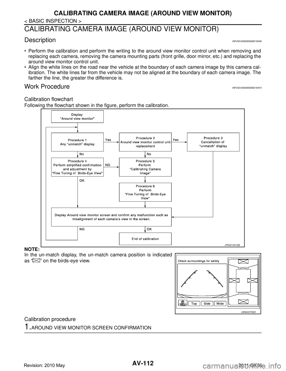
Calibration flowchart
Following the flowchart shown in the figure, perform the calibration.
NOTE:
In the un-match display, the un-match camera position is indicated
as “ ” on the birds-eye view.
Calibration procedure
1.AROUND VIEW MONITOR SCREEN CONFIRMATION
JPNIA1341GB
JSNIA2378ZZ
Revision: 2010 May2011 QX56
Page 261 of 5598

AV
CALIBRATING CAMERA IMAGE (AROUND VIEW MONITOR)
AV-113
< BASIC INSPECTION >
C
D E
F
G H
I
J
K L
M B A
O P
Check that there is the un-match display in any camera.
Is the un-match display visible?
YES >> GO TO 2.
NO >> GO TO 4.
2.CHECK THAT AROUND VIEW MONITOR CONTROL UNIT IS REPLACED
Check that the around view monitor control unit is replaced.
Is the around view monitor control unit replaced?
YES >> GO TO 3.
NO >> GO TO 5.
3.RELEASE UN-MATCH DISPLAY (PERFORM ONLY WHEN THE AROUND VIEW MONITOR CONTROL
UNIT IS REPLACED)
1. Select “Camera Cont.” of Confirmation/ Adjust ment mode, and then set to “Calibrating Camera Image”
mode.
2. Press the “ENTER” switch of the multifunction switch on each screen of “Rear Camera”, “Front Camera”, “Dr-Side Camera”\
,
“Pass-Side Camera”.
CAUTION:
Do never operate the center dial and up/down/left/right
switches. Only press the “ENTER” switch.
Never perform “Initialize Camera Image Calibration”.
3. Display the around view monitor screen, and check that there is
no malfunction such as a difference between each camera
image.
Is there a malfunction?
YES >> Calibration end
NO >> GO TO 1.
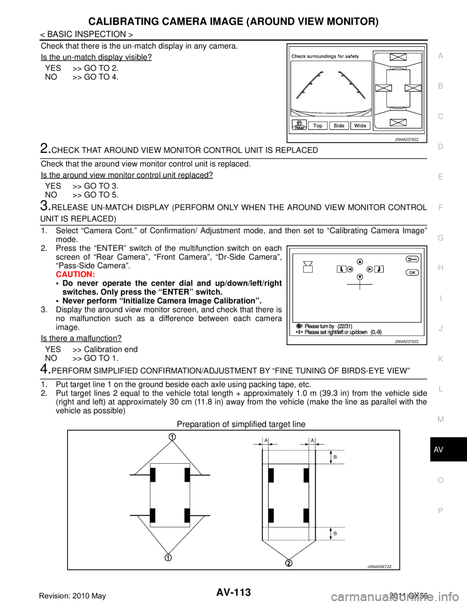
4.PERFORM SIMPLIFIED CONFIRMATION/ADJUSTM ENT BY “FINE TUNING OF BIRDS-EYE VIEW”
1. Put target line 1 on the ground beside each axle using packing tape, etc.
2. Put target lines 2 equal to the vehicle total length + approximately 1.0 m (39.3 in) from the vehicle side
(right and left) at approximately 30 cm (11.8 in) away from the vehicle (make the line as parallel with the
vehicle as possible)
Preparation of simplified target line
JSNIA2378ZZ
JSNIA2379ZZ
JSNIA0927ZZ
Revision: 2010 May2011 QX56
Page 264 of 5598

AV-116
< BASIC INSPECTION >
CALIBRATING CAMERA IMAGE (AROUND VIEW MONITOR)
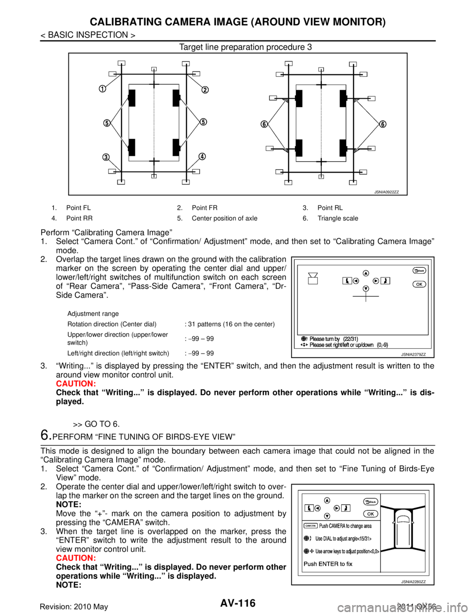
Target line preparation procedure 3
Perform “Calibrating Camera Image”
1. Select “Camera Cont.” of “Confirmation/ Adjustment” mode, and then set to “Calibrating Camera Image”
mode.
2. Overlap the target lines drawn on the ground with the calibration
marker on the screen by operating the center dial and upper/
lower/left/right switches of multifunction switch on each screen
of “Rear Camera”, “Pass-Side Camera”, “Front Camera”, “Dr-
Side Camera”.
3. “Writing...” is displayed by pressing the “ENTER” s witch, and then the adjustment result is written to the
around view monitor control unit.
CAUTION:
Check that “Writing...” is displayed . Do never perform other operations while “Writing...” is dis-
played.
>> GO TO 6.
6.PERFORM “FINE TUNING OF BIRDS-EYE VIEW”
This mode is designed to align the boundary between each camera image that could not be aligned in the
“Calibrating Camera Image” mode.
1. Select “Camera Cont.” of “Confirmation/ Adjustm ent” mode, and then set to “Fine Tuning of Birds-Eye
View” mode.
2. Operate the center dial and upper/l ower/left/right switch to over-
lap the marker on the screen and the target lines on the ground.
NOTE:
Move the “+”- mark on the camera position to adjustment by
pressing the “CAMERA” switch.
3. When the target line is overlapped on the marker, press the “ENTER” switch to write the adjustment result to the around
view monitor control unit.
CAUTION:
Check that “Writing...” is disp layed. Do never perform other
operations while “Writing...” is displayed.
NOTE:
JSNIA0922ZZ
1. Point FL 2. Point FR 3. Point RL
4. Point RR 5. Center position of axle 6. Triangle scale
Adjustment range
Rotation direction (Center dial) : 31 patterns (16 on the center)
Upper/lower direction (upper/lower
switch) :
−99 – 99
Left/right direction (left/right switch) : −99 – 99
JSNIA2379ZZ
JSNIA2280ZZ
Revision: 2010 May2011 QX56
Page 266 of 5598

AV-118
< DTC/CIRCUIT DIAGNOSIS >
U1000 CAN COMM CIRCUIT
DTC/CIRCUIT DIAGNOSIS
U1000 CAN COMM CIRCUIT
DescriptionINFOID:0000000006216248
CAN (Controller Area Network) is a serial communication line for real-time application. It is an on-vehicle mul-
tiplex communication line with high data communication s peed and excellent error detection ability. Many elec-
tronic control units are equipped onto a vehicle, and each control unit shares information and links with other
control units during operation (not independently). In CA N communication, control units are connected with 2
communication lines (CAN-H, CAN-L) allowing a high rate of information transmission with less wiring. Each
control unit transmits/receives data but selectively reads required data only.
CAN Communication Signal Chart. Refer to LAN-28, "
CAN COMMUNICATION SYSTEM : CAN Communica-
tion Signal Chart".
DTC LogicINFOID:0000000006216249
DTC DETECTION LOGIC
Diagnosis ProcedureINFOID:0000000006216250
1.PERFORM SELF-DIAGNOSTIC
1. Turn ignition switch ON and wait for 2 seconds or more.
2. Check “Self Diagnostic Result” of “MULTI AV”.
Is
“CAN COMM CIRCUIT” displayed?
YES >> Refer to LAN-18, "Trouble Diagnosis Procedure".
NO >> Refer to GI-40, "
Intermittent Incident".
DTCDisplay contents of CON-
SULT-III DTC detection condition Probable malfunction location
U1000 CAN COMM CIRCUIT
[U1000] AV control unit is not transmitting or receiving
CAN communication signal for 2 seconds or
more.
CAN communication system.
Revision: 2010 May2011 QX56