Page 13 of 420

17
Introduction
INDICATOR SYMBOLS ON THE INSTRUMENT CLUSTER
Engine coolant temperature
warning lightSeat belt warning light
High beam indicator
Turn signal indicator
Anti-lock brake system (ABS)
warning light*
Parking brake & Brake fluid
warning light
Malfunction indicator
Immobilizer indicatorGlow indicator (Diesel only)
Fuel filter warning light (Diesel only)
Tailgate open warning light*
Charging system warning light
Door ajar warning light*
Electric stability program (ESP) indicator*
ESP OFF indicator*
Front fog light indicator*
Engine oil pressure warning light
Electric power steering (EPS)
system warning light
Air bag warning light
Low tire pressure telltale* / TPMS malfunction indicator*
Rear fog light indicator
Cruise SET indicator*
AUTO STOP for ISG system indicator*
Cruise indicator*
Light on indicator
Automatic transaxle shift posi-
tion indicator (Automatic
transaxle only)
Manual transaxle shift indicator
(Manual transaxle only)
* if equipped
Low fuel level warning light
Engine oil level warning light
Low beam indicatorDoor and tailgate ajar warning light*❈For more detailed explanations, refer
to “Instrument cluster” in section 4.
JC ENG 1.QXP 9/7/2010 11:28 AM Page 7
procarmanuals.com
Page 17 of 420

Your vehicle at a glance
4
2
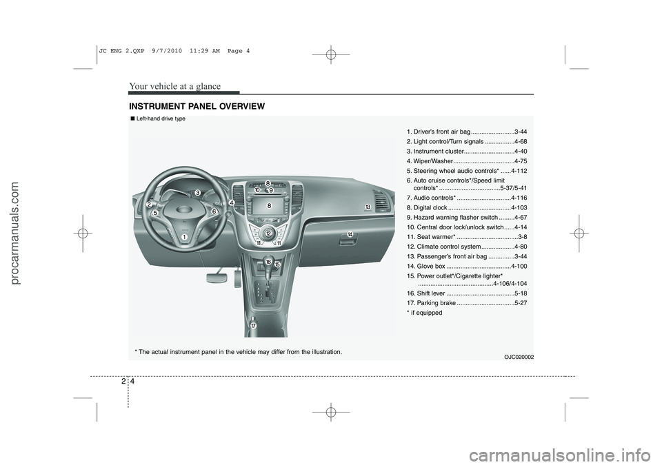
INSTRUMENT PANEL OVERVIEW
1. Driver’s front air bag .........................3-44
2. Light control/Turn signals .................4-68
3. Instrument cluster.............................4-40
4. Wiper/Washer ...................................4-75
5. Steering wheel audio controls* ......4-112
6. Auto cruise controls*/Speed limit
controls* ...................................5-37/5-41
7. Audio controls* ...............................4-116
8. Digital clock ....................................4-103
9. Hazard warning flasher switch .........4-67
10. Central door lock/unlock switch......4-14
11. Seat warmer* ...................................3-8
12. Climate control system ...................4-80
13. Passenger’s front air bag ...............3-44
14. Glove box .....................................4-100
15. Power outlet*/Cigarette lighter* ...........................................4-106/4-104
16. Shift lever .......................................5-18
17. Parking brake .................................5-27* if equipped
OJC020002
* The actual instrument panel in the vehicle may differ from the illustration.
■
Left-hand drive type
JC ENG 2.QXP 9/7/2010 11:29 AM Page 4
procarmanuals.com
Page 18 of 420

25
Your vehicle at a glance
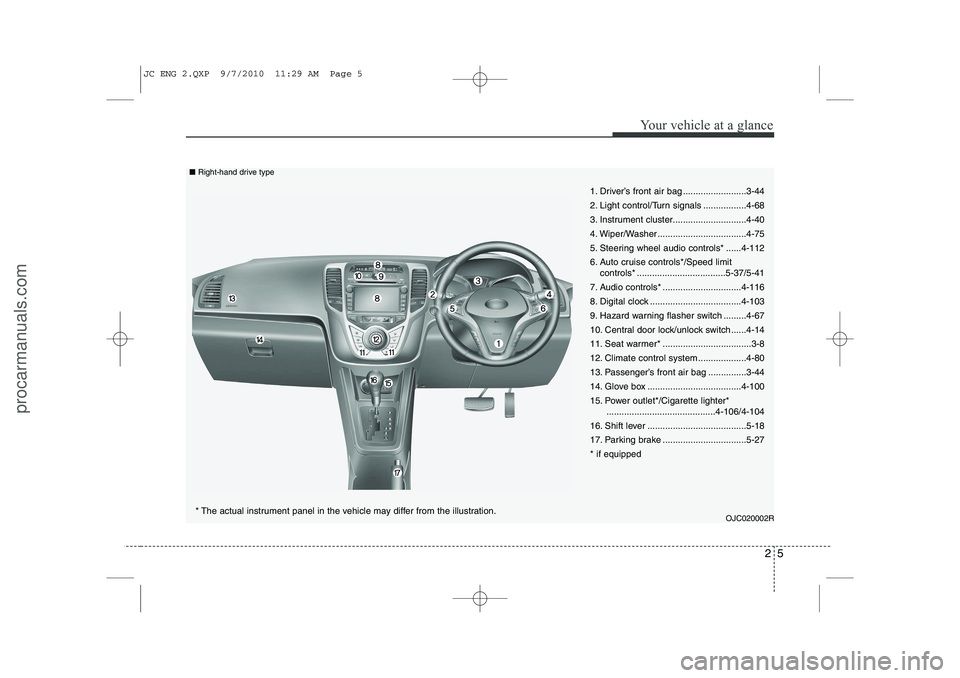
1. Driver’s front air bag .........................3-44
2. Light control/Turn signals .................4-68
3. Instrument cluster.............................4-40
4. Wiper/Washer ...................................4-75
5. Steering wheel audio controls* ......4-112
6. Auto cruise controls*/Speed limitcontrols* ...................................5-37/5-41
7. Audio controls* ...............................4-116
8. Digital clock ....................................4-103
9. Hazard warning flasher switch .........4-67
10. Central door lock/unlock switch......4-14
11. Seat warmer* ...................................3-8
12. Climate control system ...................4-80
13. Passenger’s front air bag ...............3-44
14. Glove box .....................................4-100
15. Power outlet*/Cigarette lighter* ...........................................4-106/4-104
16. Shift lever .......................................5-18
17. Parking brake .................................5-27* if equipped
OJC020002R
* The actual instrument panel in the vehicle may differ from the illustration.
■
Right-hand drive type
JC ENG 2.QXP 9/7/2010 11:29 AM Page 5
procarmanuals.com
Page 57 of 420

Safety features of your vehicle
38
3
How does the air bag system operate
Air bags are activated (able to inflate if
necessary) only when the ignition
switch is turned to the ON or STARTposition.
Air bags inflate instantly in the event of serious frontal or side collision in order
to help protect the occupants from seri-
ous physical injury.
There is no single speed at which the air bags will inflate.
Generally, air bags are designed to
inflate based upon the severity of a col-
lision and its direction. These two fac-
tors determine whether the sensors
produce an electronic deployment/inflation signal.
Air bag deployment depends on a number of factors including vehiclespeed, angles of impact and the densi-
ty and stiffness of the vehicles or
objects which your vehicle hits in the
collision. The determining, factors are
not limited to those mentioned above.
The front air bags will completely inflate and deflate in an instant.
It is virtually impossible for you to see
the air bags inflate during an accident. It is much more likely that you will sim-ply see the deflated air bags hanging
out of their storage compartments afterthe collision.
In order to help provide protection in a severe collision, the air bags must
inflate rapidly. The speed of air bag
inflation is a consequence of extreme-
ly short time in which a collision occursand the need to get the air bag
between the occupant and the vehicle
structures before the occupant impacts
those structures. This speed of inflation
reduces the risk of serious or life-
threatening injuries in a severe colli-
sion and is thus a necessary part of airbag design.
However, air bag inflation can also
cause injuries which can include facial
abrasions, bruises and broken bonesbecause the inflation speed also caus-
es the air bags to expand with a great
deal of force.
There are even circumstances under which contact with the steer-
ing wheel air bag can cause fatal
injuries, especially if the occupant
is positioned excessively close tothe steering wheel.
WARNING
To avoid severe personal injury or death caused by deploying air
bags in a collision, the driver
should sit as far back from the
steering wheel air bag as possible
(at least 250 mm (10 inches)
away). The front passenger should
always move their seat as far
back as possible and sit back intheir seat.
Air bag inflates instantly in an event of a collision, passengers
may be injured by the air bag
expansion force if they are not in
a proper position.
Air bag inflation may cause injuries including facial or bodily
abrasions, injuries from broken
glasses or burns.
JC ENG 3.QXP 9/7/2010 11:32 AM Page 38
procarmanuals.com
Page 118 of 420
Features of your vehicle
40
4
INSTRUMENT CLUSTER
OJC040040/OJC040041* The actual cluster in the vehicle may differ from the illustration.
■ Type A
■ Type B 1. Tachometer
2. Turn signal indicators
3. Speedometer
4. Warning and indicator lights
5. Engine temperature gauge
6. Fuel gauge
7. Odometer/Tripmeter** if equipped
JC ENG 4A.QXP 9/7/2010 11:38 AM Page 40
procarmanuals.com
Page 146 of 420
Features of your vehicle
68
4
The hazard warning flasher should be
used whenever you find it necessary to
stop the vehicle in a hazardous location.
When you must make such an emer-
gency stop, always pull off the road as far
as possible.
The hazard warning lights are turned on
by pushing in the hazard switch. Both
turn signal lights will blink. The hazard
warning lights will operate even though
the key is not in the ignition switch.
To turn the hazard warning lights off,
push the switch again. HAZARD WARNING FLASHER
OJC060001
JC ENG 4A.QXP 9/7/2010 11:39 AM Page 68
procarmanuals.com
Page 150 of 420

Features of your vehicle
72
4
To flash the headlights, pull the lever
towards you. It will return to the normal
(low beam) position when released. The
headlight switch does not need to be on
to use this flashing feature. Turn signals and lane change sig- nals
The ignition switch must be on for the
turn signals to function. To turn on the
turn signals, move the lever up or down
(A). The green arrow indicators on the
instrument panel indicate which turn sig-
nal is operating. They will self-cancel
after a turn is completed. If the indicator
continues to flash after a turn, manually
return the lever to the off position.To signal a lane change, move the turn
signal lever slightly and hold it in position
(B). The lever will return to the off positionwhen released.
If an indicator stays on and does not
flash or if it flashes abnormally, one of the
turn signal bulbs may be burned out andwill require replacement.
One-touch lane change function
(if equipped)
To activate an one-touch lane change
function, move the turn signal lever
slightly and then release it. The lane
change signals will blink 3 times.
✽✽ NOTICE
If an indicator flash is abnormally quick
or slow, a bulb may be burned out or
have a poor electrical connection in the
circuit.
OED040804OED040802
JC ENG 4A.QXP 9/7/2010 11:40 AM Page 72
procarmanuals.com
Page 189 of 420
4 111
Features of your vehicle
✽✽NOTICE
If you install an after market HID head
lamp, your vehicle’s audio and electron-ic device may malfunction.
Antenna
Roof antenna
Your vehicle uses a roof antenna to
receive both AM and FM signals. This
antenna can be removed. To remove the
antenna, turn it counter clockwise, To
install the antenna, turn it clockwise.
AUDIO SYSTEM
OYN049126
CAUTION
• Before entering a place with a low
height clearance or a car wash,
remove the antenna by rotating it counter-clockwise. If not, theantenna may be damaged.
When reinstalling your antenna, it is important that it is fully tight-ened to ensure proper reception.
When cargo is loaded on the roof rack, do not place the cargo nearthe antenna pole to ensure proper
reception.
JC ENG 4B AUDIO.QXP 9/7/2010 11:47 AM Page 111
procarmanuals.com