Page 349 of 400

Although this seems like a simple
procedure, you should take several
precautions.Open the hood, and check the
physical condition of the battery.
In very cold weather, check the
condition of the electrolyte. If it
seems slushy or f rozen, do not try
jump starting until it thaws.
To jump start your vehicle:
Turn of f all the electrical
accessories: heater, A/C, audio
system, lights, etc. Put the
transmission in neutral (manual)
or Park (automatic), and set the
parking brake. The numbers in the illustrations
show you the order to connect the
jumper cables.
You cannot start a vehicle with an
automatic transmission by pushing
or pulling it. 1. 2.
CONT INUED
Jump Starting
T aking Care of t he Unexpect ed
345
BOOSTER BATTERY
DX, DX-G, LX, SE, EX, EX-L
A battery can explode if you do
not follow the correct procedure,
seriously injuring anyonenearby.
Keep all sparks, open flames,
and smoking materials away
from the battery.
If a battery sits in extreme cold, the
electrolyte inside can f reeze.
Attempting to jump start with a f rozen
battery can cause it to rupture.
Main Menu
Page 351 of 400

CONT INUED
Once your vehicle is running,
disconnect the negative cable f rom
your vehicle, then f rom the
booster battery. Disconnect the
positive cable f rom your vehicle,
then from the booster battery.
Keep the ends of the jumper cables
away from each other and any metal
on the vehicle until everything is
disconnected. Otherwise, you may
cause an electrical short. If the vehicle overheats, you
should take immediate action. The
only indication may be the
temperature gauge climbing to or
above the red mark. Or you may
see steam or spray coming f rom
under the hood.
If you see steam and/or spray
coming f rom under the hood, turn
of f the engine. Wait until you see
no more signs of steam or spray,
then open the hood.
The reading of the vehicle’s
temperature gauge should stay in
the midrange. If it climbs to the red
mark, you should determine the
reason (hot day, driving up a steep
hill, etc.).
Saf ely pull to the side of the road.
Put the transmission in neutral
(manual) or Park (automatic), and
set the parking brake. Turn of f all
accessories, and turn on the
hazard warning lights.
7.
1. 2.
Jump Starting, If the Engine Overheats
If the Engine Overheats
T aking Care of t he Unexpect ed
347
Steam and spray from an
overheated engine can
seriously scald you.
Do not open the hood if steam
is coming out.
Driving with the temperature gauge
reading at the red mark can cause
serious damage to the engine.
Main Menu
Page 355 of 400

However, if the brake pedal does not
f eel normal, you should take
immediate action. A problem in one
part of the system’s dual circuit
design will still give you braking at
two wheels. You will f eel the brake
pedal go down much f arther bef ore
the vehicle begins to slow down, and
you will have to press harder on the
pedal.
If you must drive the vehicle a short
distance in this condition, drive
slowly and caref ully.
Slow down by shif ting to a lower
gear, and pull to the side of the road
when it is saf e. Because of the long
distance needed to stop, it is
hazardous to drive the vehicle. You
should have it towed and repaired as
soon as possible (see
on page ).
If the f luid level is low, take your
vehicle to a dealer, and have the
brake system inspected f or leaks or
worn brake pads.
If the brake system indicator comes
on while driving, the brake f luid level
is probably low. Press lightly on the
brake pedal to see if it f eels normal.
If it does, check the brake f luid level
thenexttimeyoustopataservice
station (see page ). The brake system
indicator normally
comes on when
you turn the ignition switch to the
ON (II) position and as a reminder to
check the parking brake. It will stay
on if you do not f ully release the
parking brake. If the ABS indicator and the VSA
system indicator (if equipped) come
on with the brake system indicator,
have your vehicle inspected by your
dealer immediately.
310 358Emergency
Towing
Brake System Indicator
T aking Care of t he Unexpect ed
351
Canada
U.S.
Main Menu
Page 357 of 400
CONT INUED
Check each of the large f uses in
the under-hood f use box by
looking through the top at the wire
inside. Removing these f uses
requires a Phillips-head screw-
driver.
Turn the ignition switch to the
LOCK (0) position. Make sure the
headlights and all other
accessories are of f .
Remove the cover f rom the f use
box. Check the smaller f uses in the
under-hood f use box and all the
fuses in the interior fuse box by
pulling out each one with the f use
pullerprovidedonthebackof the
under-hood f use box cover.
4.
3.
1. 2.
Fuses
T aking Care of t he Unexpect ed
353
FUSE BLOWN FUSE BLOWN
FUSE PULLER
Main Menu
Page 360 of 400
�µ �µ �µ �µ
�Î�Î
�Î
�Î �Î
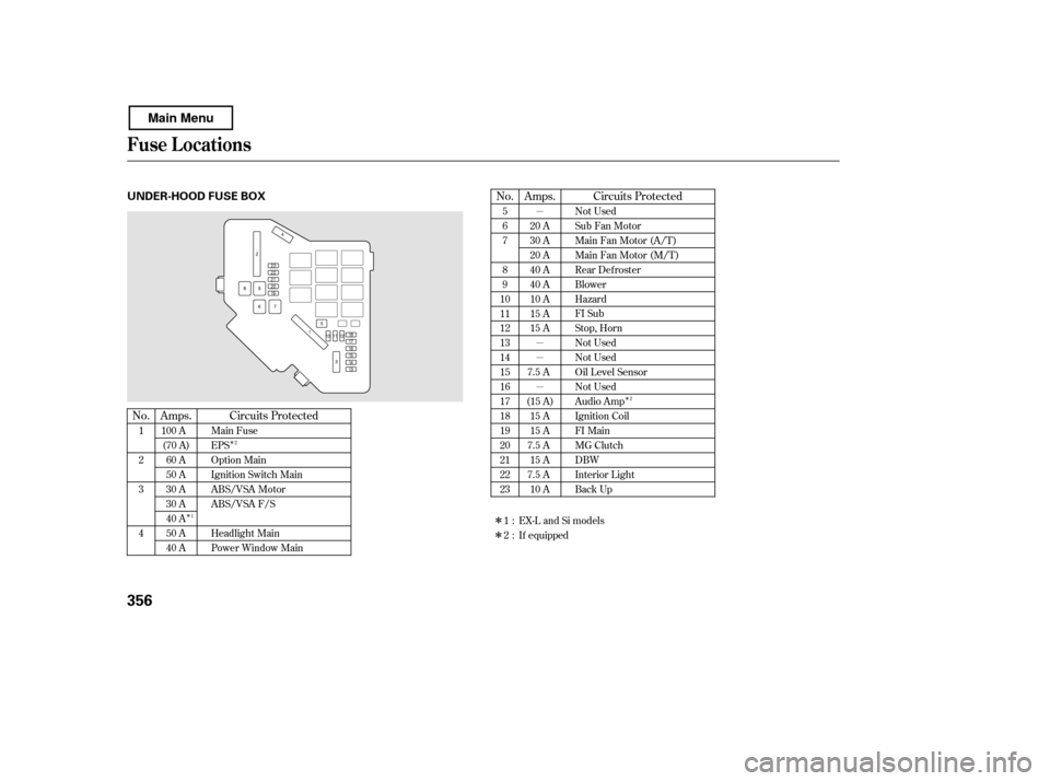
No. No. Amps.
Circuits Protected Circuits Protected
Amps.
1 23 4 5 67 8 9
1011121314151617181920212223
If equipped20 A
30 A
20 A
40 A
40 A
10 A
15 A
15 A
7.5 A
(15 A) 15 A
15 A
7.5 A
15 A
7.5 A
10 A
Main FuseEPS
Option Main
Ignition Switch Main
ABS/VSA Motor
ABS/VSA F/S
Headlight Main
Power Window Main Not Used
Sub Fan Motor
Main Fan Motor (A/T)
Main Fan Motor (M/T)
Rear Defroster
Blower
Hazard
FI Sub
Stop, Horn
Not Used
Not Used
Oil Level Sensor
Not Used
Audio Amp
Ignition Coil
FI Main
MG Clutch
DBW
Interior Light
Back Up
100 A
(70 A) 60 A
50 A
30 A
30 A
40 A
50 A
40 A 1:2:
EX-L and Si models2 2
1
Fuse Locations
356
UNDER-HOOD FUSE BOX
Main Menu
Page 361 of 400

�Î�Î
�Î �Î
�Î
�µ �µ �µ �µ �µ �µ�µ�µ
�Î
No.
No. Amps. Circuits ProtectedNo. Circuits Protected
Circuits Protected
Amps. Amps.
12345678
9
10111213141516 7.5 A
7.5 A
10 A
10 A
10 A
7.5 A
7.5 A 10 A ODS (Occupant Detection
System)
Meter
SRS
Right Headlight High Beam
Left Headlight High Beam
Small Lights (Interior)
Small Lights (Exterior)
Right Headlight Low Beam 1718192021222324252627282930 31 32333435363738Left Headlight Low Beam
Headlight High Beam Main
Small Lights Main
Not Used
Headlight Low Beam Main
Not Used
Not Used
Moonroof
Door Lock
Driver’s Power Window
HAC Option
Rear Accessory Socket
Accessory
Front Passenger’s Power
Window
Not Used
Not Used
Not Used
Not Used
Accessory, Radio
IG2 HAC
Daytime Running Lights
Front Wiper
Power Window
Fuel Pump
IG1 ACG
ABS/VSA
Heated Seats
Front Fog Lights
TPMS
Not Used
If equipped
7.5 A
15 A
10 A
7.5 A
(15 A)
(20 A)
(7.5 A) 10 A
20 A
15 A
20 A
(20 A) 20 A
20 A
(20 A)
(15 A) 15 A
20 A
7.5 A 10 A
7.5 A
30 A
:
Fuse Locations
T aking Care of t he Unexpect ed
357
INTERIOR FUSE BOX
Main Menu
Page 369 of 400

�µ�µ
�Î �Î �µ �µ�µ �µ �µ�µ�µ�µ�µ�µ�µ�µ�µ
�Î�Î
�Î �Î �Î�Î
�Î
�Î
�Î �Î
�Î�Î �Î�Î�Î�Î�Î�Î�Î�Î
�Î�Î�Î�Î�Î�Î�Î�Î�Î�Î�Î�Î�Î�Î�Î
Specif ications
T echnical Inf ormation
365
Air Conditioning
Capacities
Lights
Refrigerant type
Charge quantity
Lubricant oil type
HFC-134a (R-134a)
14.1 15.9 oz (400 450 g) SP-10
60 W
12 V
51 W
Including the coolant in the reserve tank and that remaining in
the engine
Reserve tank capacity:
Excluding the oil remaining in the engine 13.2 US gal (50)
1.45 US gal (5.5)
1.37 US gal (5.2)
1.19 US gal (4.5)
1.88 US gal (7.1)
1.72 US gal (6.5)
1.80 US gal (6.8)
3.9 US qt (3.7
)
4.6 US qt (4.4)
3.7 US qt (3.5)
4.4 US qt (4.2)
4.8 US qt (4.5)
5.8 US qt (5.5)
1.5 US qt (1.4)
1.6 US qt (1.5)
1.7 US qt (1.6)
1.8 US qt (1.7)
2.5 US qt (2.4)
6.08 US qt (5.75)
2.6 US qt (2.5
)
4.8 US qt (4.5)
0.11 US gal (0.4
)
Fuel tank
Engine
coolant
Engine oil Manual
transmission
fluid Automatic
transmission
fluid
Windshield
washer
reservoir
12 V
5W
8W
8W
21 W
18 W
3CP
21/5 W
21 W
12 V 55 W
Headlights (HI)
Headlights (LO)
Front turn signal/Side marker/
Parking light
Fog lights
Rear turn signal lights
Stop/Taillights
Rear side marker lights
Back-up lights
High-mount brake light
License plate lights
Ceiling light
Spotlights
Trunk light
12 V28/8 W
12 V
12 V
12 V
12 V
12 V
12 V 3 CP
12 V
12 V
12 V
Change Total
Change
Including
filter
Without filter
Total
ChangeTotal
Change Total
U.S. Vehicles
Canada
Vehicles Approx.
Si
A/T
M/T
A/T
M/T
(HB3)(HB4)
EX, EX-L, Si:
U.S.: DX, LX, EX, EX-L U.S. DX and LX
1:
Replacement of the light should be done by yourdealer.
2 : If equipped (H11)
(Amber)
(Amber)
4:6:
1: 2: 3:5: Canada: DX-G, SE
Canada: DX-G, SE Canada: DX-G, SE, EX-L
2
1
1 2
3, 4
3, 56
3, 4
3, 56
3, 46
3, 46
3, 46
3, 56
3, 56
Main Menu
Page 377 of 400
, oxides of nitrogen
(NOx), and hydrocarbons (HC).
Gasoline evaporating")
�Î
�Î
The burning of gasoline in your
vehicle’s engine produces several by-
products. Some of these are carbon
monoxide (CO), oxides of nitrogen
(NOx), and hydrocarbons (HC).
Gasoline evaporating f rom the tank
also produces hydrocarbons. Con-
trolling the production of NOx, CO,
and HC is important to the environ-
ment. Under certain conditions of
sunlight and climate, NOx and HC
react to f orm photochemical ‘‘smog.’’
Carbon monoxide does not contri-
bute to smog creation, but it is a
poisonous gas. The United States Clean Air Act
sets standards f or automobile
emissions. It also requires that
automobile manufacturers explain to
owners how their emissions controls
workandwhattodotomaintain
them. This section summarizes how
the emissions controls work.
In Canada, Honda vehicles comply
with the Canadian emission
requirements, as specif ied in an
agreement with Environment
Canada, at the time they are
manuf actured.
Your vehicle has a positive
crankcase ventilation system. This
keeps gasses that build up in the
engine’s crankcase f rom going into
the atmosphere. The positive
crankcase ventilation valve routes
them from the crankcase back to the intake manif old. They are then
drawn into the engine and burned.
As gasoline evaporates in the f uel
tank, an evaporative emissions
control canister f illed with charcoal
adsorbs the vapor. It is stored in this
canister while the engine is of f . Af ter
the engine is started and warmed up,
the vapor is drawn into the engine
and burned during driving.
The onboard ref ueling vapor
recovery (ORVR) system captures
the f uel vapors during ref ueling. The
vapors are adsorbed in a canister
f illed with activated carbon. While
driving, the f uel vapors are drawn
into the engine and burned of f .
The Clean Air Act
Crankcase Emissions Control
System
Evaporative Emissions Control
System
Onboard Ref ueling Vapor
Recovery
Emissions Cont rols
T echnical Inf ormation
373
Main Menu