Page 100 of 2057

Suspension System
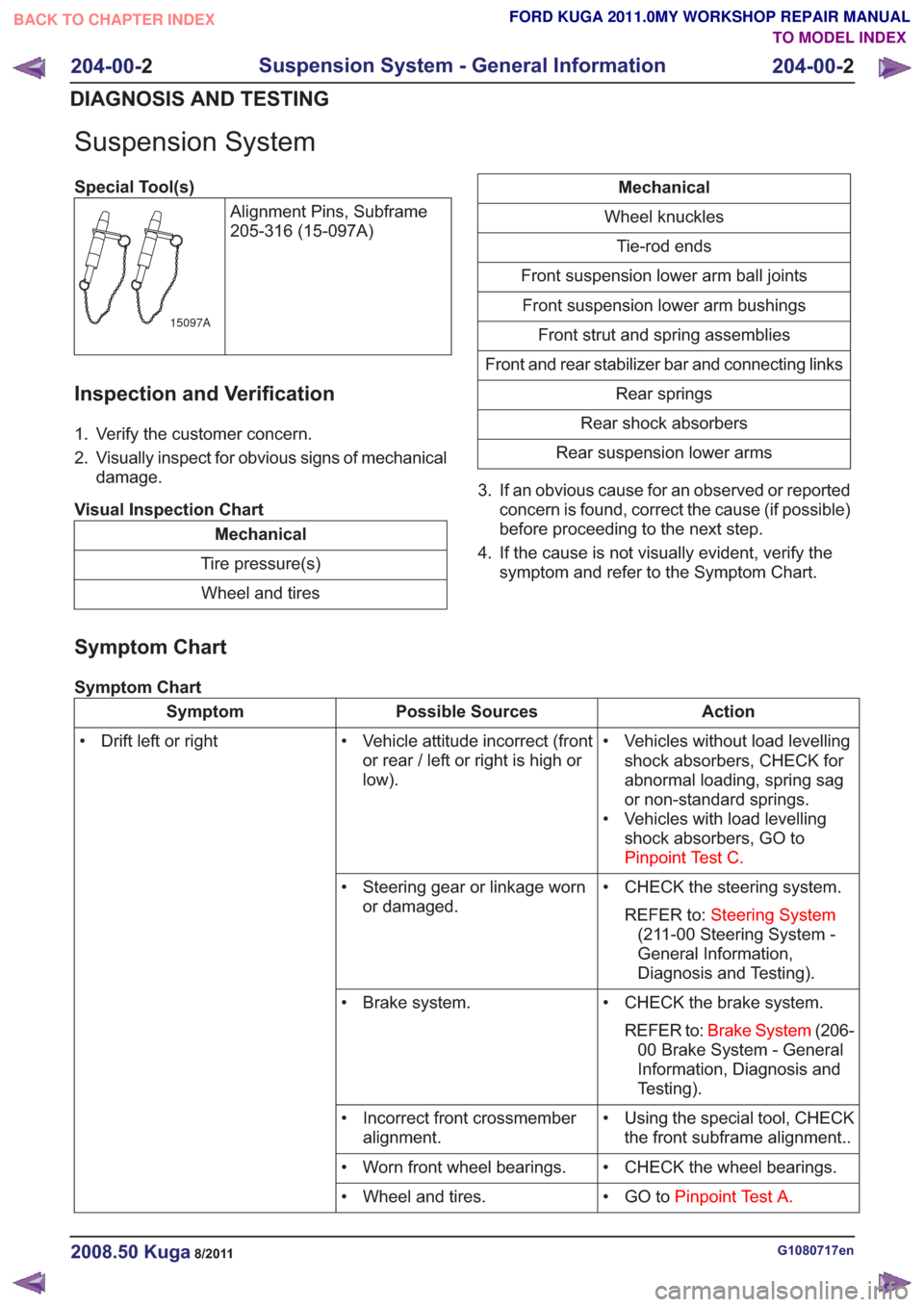
Special Tool(s)Alignment Pins, Subframe
205-316 (15-097A)
15097A
Inspection and Verification
1. Verify the customer concern.
2. Visually inspect for obvious signs of mechanicaldamage.
Visual Inspection Chart
Mechanical
Tire pressure(s) Wheel and tires
Mechanical
Wheel knuckles Tie-rod ends
Front suspension lower arm ball joints Front suspension lower arm bushings Front strut and spring assemblies
Front and rear stabilizer bar and connecting links Rear springs
Rear shock absorbers
Rear suspension lower arms
3. If an obvious cause for an observed or reported concern is found, correct the cause (if possible)
before proceeding to the next step.
4. If the cause is not visually evident, verify the symptom and refer to the Symptom Chart.
Symptom Chart
Symptom Chart
Action
Possible Sources
Symptom
• Vehicles without load levellingshock absorbers, CHECK for
abnormal loading, spring sag
or non-standard springs.
• Vehicles with load levelling shock absorbers, GO to
Pinpoint Test C.
• Vehicle attitude incorrect (front
or rear / left or right is high or
low).
• Drift left or right
• CHECK the steering system.REFER to: Steering System
(211-00 Steering System -
General Information,
Diagnosis and Testing).
• Steering gear or linkage worn
or damaged.
• CHECK the brake system.REFER to: Brake System (206-
00 Brake System - General
Information, Diagnosis and
Testing).
• Brake system.
• Using the special tool, CHECKthe front subframe alignment..
• Incorrect front crossmember
alignment.
• CHECK the wheel bearings.
• Worn front wheel bearings.
• GO toPinpoint Test A.
• Wheel and tires.
G1080717en2008.50 Kuga8/2011
204-00- 2
Suspension System - General Information
204-00- 2
DIAGNOSIS AND TESTING
TO MODEL INDEX
BACK TO CHAPTER INDEX
FORD KUGA 2011.0MY WORKSHOP REPAIR MANUAL
Page 299 of 2057

Audio System – Overview
Keycode entry - vehicle with standard
audio system
The keycode is entered via the MENU button and
the arrow buttons. The keycode is then confirmed
with the rotary/pushbutton in the middle of the unit.
Only a limited number of attempts to enter the
correct keycode are allowed. The number of
attempts already made is shown in the display.
Following every subsequent unsuccessful attempt,
an uninterrupted waiting period must be observed
before a further attempt can be made.
The display then shows "WAIT XX" and counts
down to "0", provided the ignition remains switched
on. Once this time has expired, a new attempt can
be made to enter the keycode.
After a certain number of unsuccessful attempts
at entering the keycode, the display will show
"LOCKED" or "SAFE". The customer will now be
unable to switch on the device.
The authorized Ford dealer can remove the lock
and can make up to three further attempts.
Vehicle Identification Number (VID) -
entry - vehicle with standard audio
system
It is often extremely difficult to return stolen audio
units which have been seized by the police to their
owners.
Therefore, many Ford audio units offer the option
of, for example, entering a vehicle identification
number into the unit.
For Ford audio systems, the abbreviation VID is
used to refer to the Vehicle Identification Number.
The VIN (chassis number) or, for instance, the number plate number can be entered and this
fulfills the security function.
The VIN is programmed ex works. If the unit is
replaced, the VIN is automatically transferred by
the diagnostics system during configuration.
Self-check routine - vehicles with
standard audio system.
The audio unit must be in radio mode before
entering the Self-Diagnostic Mode.
To enter the audio unit Self-Diagnostic Mode,
switch the audio unit ON. Press pre-set buttons 3
and 6 simultaneously and then release them again.
Keycode entry - vehicles with upgraded
audio system
The station keys are used to enter the keycode.
Station key 5 is used to confirm the keycode.
Only a limited number of attempts to enter the
correct keycode are allowed. The number of
attempts already made is shown in the display.
After the second unsuccessful attempt, the person
entering the keycode will have to wait for an
uninterrupted period of time before making the next
attempt.
The display then shows "WAIT XX" and counts
down to "0", provided the ignition remains switched
on. Once this time has expired, a new attempt can
be made to enter the keycode.
After a certain number of unsuccessful attempts
at entering the keycode, the display will show
"LOCKED" or "SAFE". The customer will now be
unable to switch on the device.
G1055645en
2008.50 Kuga 8/2011 415-01-3
Information and Entertainment System
415-01-3
DESCRIPTION AND OPERATIONTO MODEL INDEX
BACK TO CHAPTER INDEX
FORD KUGA 2011.0MY WORKSHOP REPAIR MANUALE99206 E99207
Page 304 of 2057

Description
Item
In-car entertainment
1
Genetic electronic module (GEM).
2
instrument cluster
3
ABS4
ABS sensor assembly
5
Rear LH mid/bass range speaker
6
Rear RH mid/bass range speaker
7
Rear LH tweeter
8 Description
Item
Rear RH tweeter
9
AUX port
10
Radio remote control.
11
FM/AM antenna
12
Front LH mid/bass speaker
13
Front RH mid/bass speaker
14
Front LH tweeter
15
Front RH tweeter
16
System Operation
In-car entertainment
The audio system is connected to the MS CAN
network and uses an internal amplifier which
directly drives the system speakers. It can only be
operated via the head unit and the radio remote
control. The head unit is connected to the vehicle
on the medium speed CAN bus. This allows the
unit to be interrogated for diagnostic purposes.
The automatic volume control (AVC) adjusts the
audio volume depending on the driving speed. The
audio device receives the necessary signals for
the ABS (anti-lock brake system) wheel sensors
from the instrument cluster on the MS-CAN. As
vehicle speed increases the audio level is adjusted
to compensate for extra road and vehicle noise.
Eight AVC settings are possible.
To choose the setting for automatic volume control,
press the MENU button until the AVC display
appears.
The required adjustment level is determined by the
Infotainment control unit based on the driving
speed signal. The vehicle speed signal is received
over the CAN. The signal is an average of the four
wheel speed sensor signals. Should an invalid
speed signal be received the AVC will not alter the
output volume.
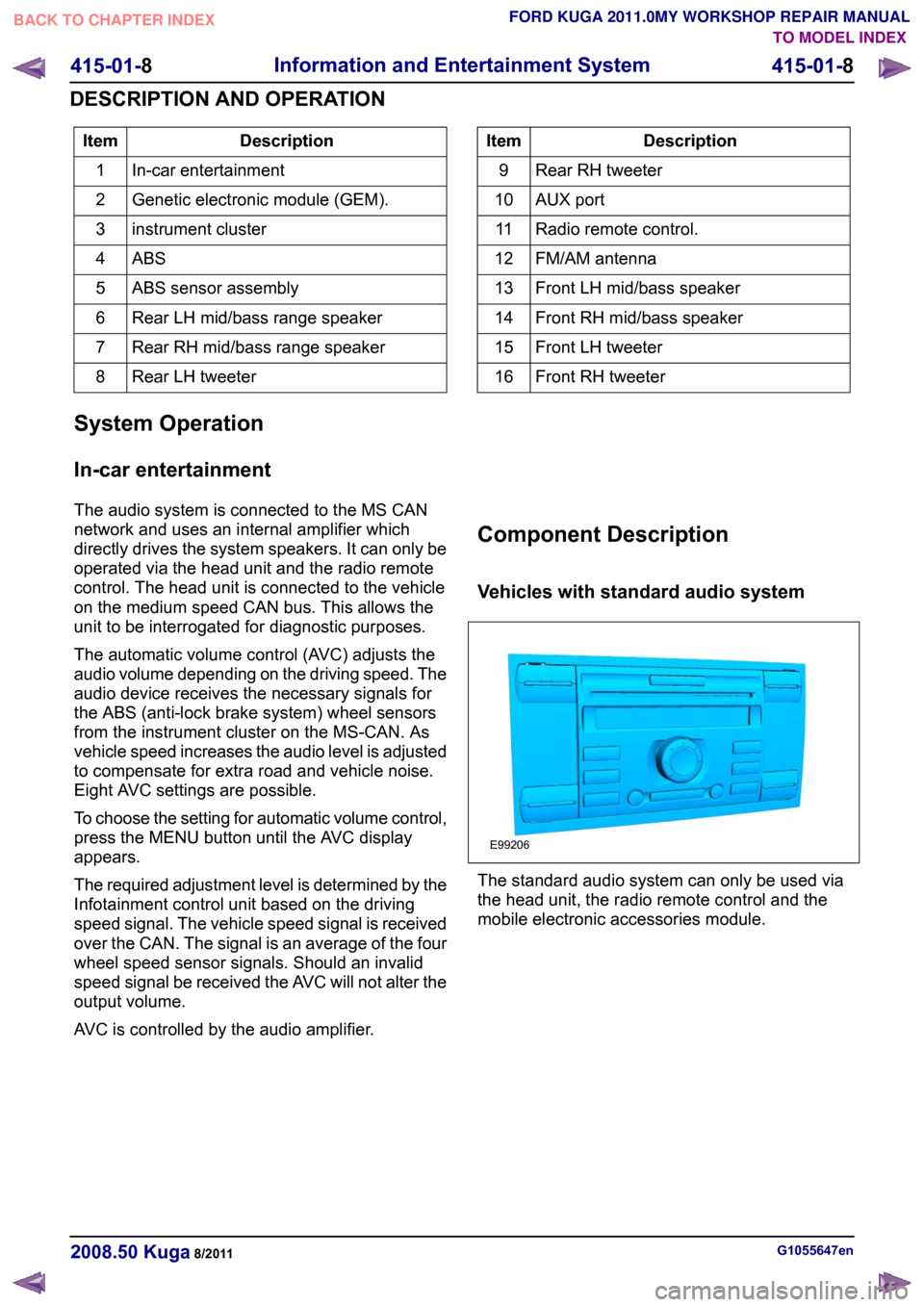
AVC is controlled by the audio amplifier. Component Description
Vehicles with standard audio system
The standard audio system can only be used via
the head unit, the radio remote control and the
mobile electronic accessories module.
G1055647en
2008.50 Kuga 8/2011 415-01-8
Information and Entertainment System
415-01-8
DESCRIPTION AND OPERATIONTO MODEL INDEX
BACK TO CHAPTER INDEX
FORD KUGA 2011.0MY WORKSHOP REPAIR MANUALE99206
Page 1180 of 2057
Front Wheel Bearing(14 411 0; 14 411 4; 14 412 0; 14 414 4;14 416 4)
Special Tool(s) / General Equipment
204-158
Collet for 205-295
14038
204-348
Remover/Installer, Wheel
Hub/Wheel Bearing
E42977
204-740
Remover/Installer, Wheel
Hub/Bearing
E100141
205-071-01
Adapter for 205-071 (Thrust
Pad)
15026A01
205-080
Installer, Differential Bearing
205080
205-255
Installer, Front Wheel Hub
Seal
14045
Special Tool(s) / General Equipment205-295
Remover, Bearing (Main
Tool)
15050A
Hydraulic Press
Removal
1.Refer to: Wheel Knuckle (204-01 Front
Suspension, Removal and Installation).
2. NOTE: Note the position of the component
before removal.
E99320
G1000206en2008.50 Kuga8/2011
204-01- 9
Front Suspension
204-01- 9
REMOVAL AND INSTALLATION
TO MODEL INDEX
BACK TO CHAPTER INDEX
FORD KUGA 2011.0MY WORKSHOP REPAIR MANUAL
Page 1181 of 2057
3.Special Tool(s): 205-080, 204-348
General Equipment: Hydraulic Press
E99321
205-080
204-348
4.Special Tool(s): 205-255, 204-740
General Equipment: Hydraulic Press
E99322
205-255
204-740/2
5.Special Tool(s): 205-071-01, 205-295, 204-158
G1000206en2008.50 Kuga8/2011
204-01- 10
Front Suspension
204-01- 10
REMOVAL AND INSTALLATION
TO MODEL INDEX
BACK TO CHAPTER INDEX
FORD KUGA 2011.0MY WORKSHOP REPAIR MANUAL
Page 1182 of 2057
E99400
205-071-01
204-158205-295
6.
E103391
Installation
1. NOTE:Make sure that the sensor ring is
correctly located.
G1000206en2008.50 Kuga8/2011
204-01- 11
Front Suspension
204-01- 11
REMOVAL AND INSTALLATION
TO MODEL INDEX
BACK TO CHAPTER INDEX
FORD KUGA 2011.0MY WORKSHOP REPAIR MANUAL
Page 1183 of 2057
Install the wheel bearing with the black colored
wheel speed sensor ring facing towards the
transmission side.
Special Tool(s): 204-740
General Equipment: Hydraulic Press
E99402
204-740/1
2.Special Tool(s): 204-740
General Equipment: Hydraulic Press
E99403
204-740/1
3. NOTE: Make sure that this component is
installed to the noted removal position.
E99320
4. Refer to: Wheel Knuckle (204-01 Front
Suspension, Removal and Installation).
G1000206en2008.50 Kuga8/2011
204-01- 12
Front Suspension
204-01- 12
REMOVAL AND INSTALLATION
TO MODEL INDEX
BACK TO CHAPTER INDEX
FORD KUGA 2011.0MY WORKSHOP REPAIR MANUAL
Page 1192 of 2057
Wheel Knuckle(14 343 0)
Special Tool(s)204-052
Lever, Wheel Knuckle
14026A
204-602
Installer, Halfshaft
E62067
204-605
Separator, Lower Arm Ball
Joint
E63772
204-609
Protection Cap, Ball Joint
Gaiter
E75372
211-020
Separator, Ball Joint
13006
Removal
NOTE:Removal steps in this procedure may
contain installation details. 1.
E99184
2.
Refer to: Wheel and Tire (204-04 Wheels and
Tires, Removal and Installation).
3.
E99195
4.
E98543
x7
5. WARNING: Make sure that no load is placed on the brake hose.
Torque: 120Nm
G1000209en2008.50 Kuga8/2011
204-01- 21
Front Suspension
204-01- 21
REMOVAL AND INSTALLATION
TO MODEL INDEX
BACK TO CHAPTER INDEX
FORD KUGA 2011.0MY WORKSHOP REPAIR MANUAL