2011 FORD KUGA Wiring
[x] Cancel search: WiringPage 1758 of 2057
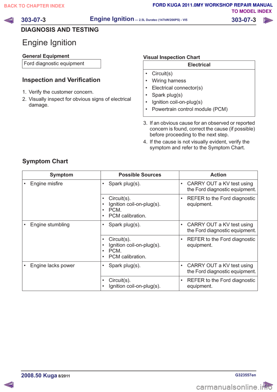
Engine Ignition
General EquipmentFord diagnostic equipment
Inspection and Verification
1. Verify the customer concern.
2. Visually inspect for obvious signs of electrical damage. Visual Inspection Chart
Electrical
• Circuit(s)
• Wiring harness
• Electrical connector(s)
• Spark plug(s)
• Ignition coil-on-plug(s)
• Powertrain control module (PCM)
3. If an obvious cause for an observed or reported concern is found, correct the cause (if possible)
before proceeding to the next step.
4. If the cause is not visually evident, verify the symptom and refer to the Symptom Chart.
Symptom Chart
Action
Possible Sources
Symptom
• CARRY OUT a KV test usingthe Ford diagnostic equipment.
• Spark plug(s).
• Engine misfire
• REFER to the Ford diagnosticequipment.
• Circuit(s).
• Ignition coil-on-plug(s).
•PCM.
• PCM calibration.
• CARRY OUT a KV test usingthe Ford diagnostic equipment.
• Spark plug(s).
• Engine stumbling
• REFER to the Ford diagnosticequipment.
• Circuit(s).
• Ignition coil-on-plug(s).
•PCM.
• PCM calibration.
• CARRY OUT a KV test usingthe Ford diagnostic equipment.
• Spark plug(s).
• Engine lacks power
• REFER to the Ford diagnosticequipment.
• Circuit(s).
• Ignition coil-on-plug(s).
G323557en2008.50 Kuga8/2011
303-07-
3
Engine Ignition— 2.5L Duratec (147kW/200PS) - VI5303-07-
3
DIAGNOSIS AND TESTING
TO MODEL INDEX
BACK TO CHAPTER INDEX
FORD KUGA 2011.0MY WORKSHOP REPAIR MANUAL
Page 1763 of 2057
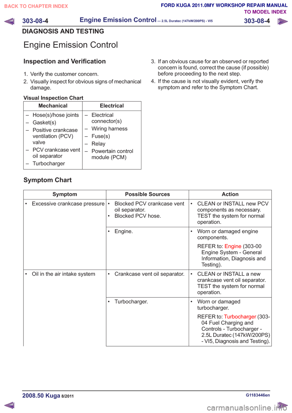
Engine Emission Control
Inspection and Verification
1. Verify the customer concern.
2. Visually inspect for obvious signs of mechanicaldamage.
Visual Inspection Chart
Electrical
Mechanical
– Electricalconnector(s)
– Wiring harness
– Fuse(s)
– Relay
– Powertain control module (PCM)
– Hose(s)/hose joints
– Gasket(s)
– Positive crankcase
ventilation (PCV)
valve
– PCV crankcase vent oil separator
– Turbocharger 3. If an obvious cause for an observed or reported
concern is found, correct the cause (if possible)
before proceeding to the next step.
4. If the cause is not visually evident, verify the symptom and refer to the Symptom Chart.
Symptom Chart
Action
Possible Sources
Symptom
• CLEAN or INSTALL new PCVcomponents as necessary.
TEST the system for normal
operation.
• Blocked PCV crankcase vent
oil separator.
• Blocked PCV hose.
• Excessive crankcase pressure
• Worn or damaged enginecomponents.
REFER to: Engine(303-00
Engine System - General
Information, Diagnosis and
Testing).
• Engine.
• CLEAN or INSTALL a newcrankcase vent oil separator.
TEST the system for normal
operation.
• Crankcase vent oil separator.
• Oil in the air intake system
• Worn or damagedturbocharger.
REFER to: Turbocharger (303-
04 Fuel Charging and
Controls - Turbocharger -
2.5L Duratec (147kW/200PS)
- VI5, Diagnosis and Testing).
• Turbocharger.
G1183446en2008.50 Kuga8/2011
303-08-
4
Engine Emission Control— 2.5L Duratec (147kW/200PS) - VI5303-08-
4
DIAGNOSIS AND TESTING
TO MODEL INDEX
BACK TO CHAPTER INDEX
FORD KUGA 2011.0MY WORKSHOP REPAIR MANUAL
Page 1774 of 2057
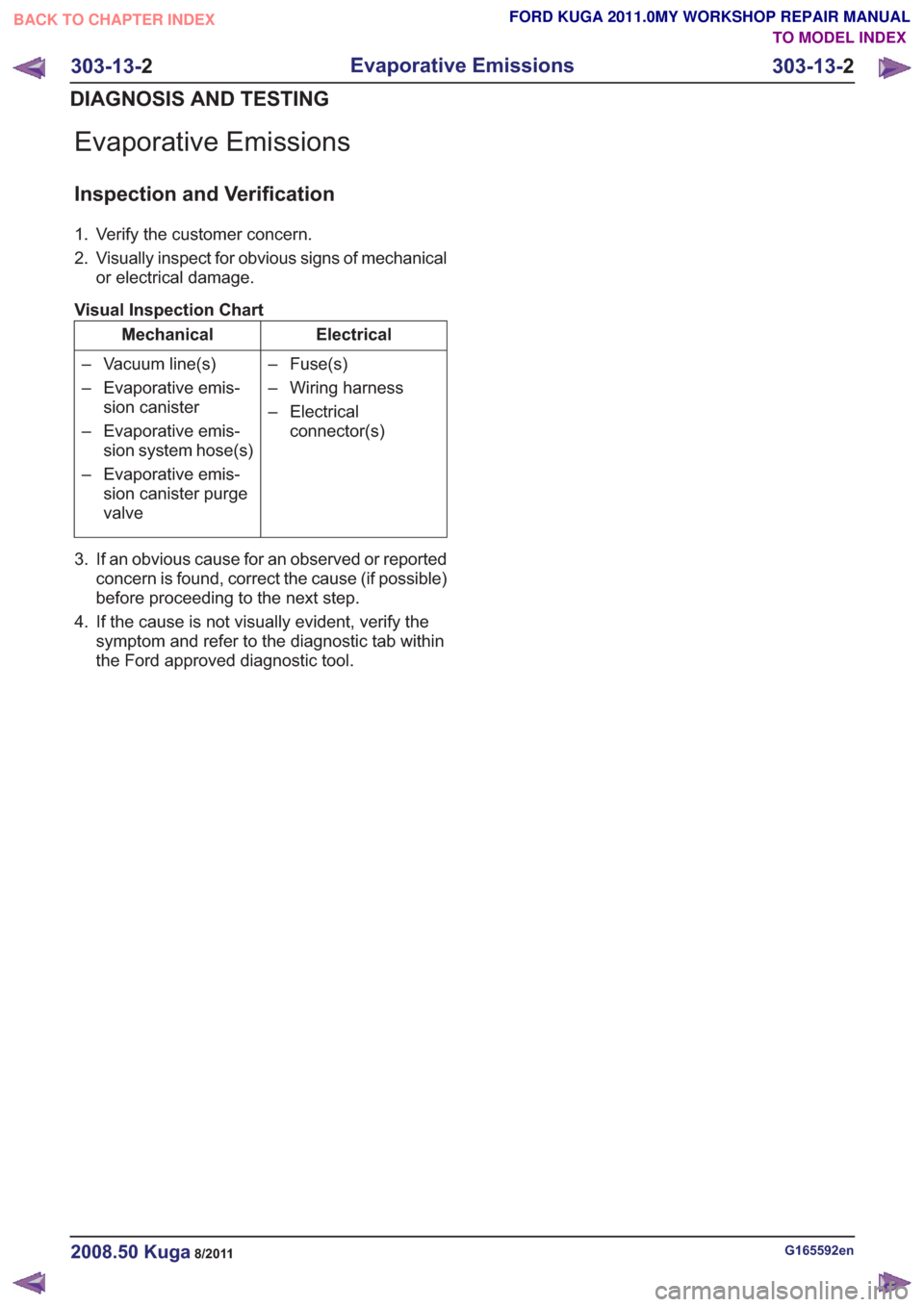
Evaporative Emissions
Inspection and Verification
1. Verify the customer concern.
2. Visually inspect for obvious signs of mechanicalor electrical damage.
Visual Inspection Chart
Electrical
Mechanical
– Fuse(s)
– Wiring harness
– Electricalconnector(s)
– Vacuum line(s)
– Evaporative emis-
sion canister
– Evaporative emis- sion system hose(s)
– Evaporative emis- sion canister purge
valve
3. If an obvious cause for an observed or reported concern is found, correct the cause (if possible)
before proceeding to the next step.
4. If the cause is not visually evident, verify the symptom and refer to the diagnostic tab within
the Ford approved diagnostic tool.
G165592en2008.50 Kuga8/2011
303-13- 2
Evaporative Emissions
303-13- 2
DIAGNOSIS AND TESTING
TO MODEL INDEX
BACK TO CHAPTER INDEX
FORD KUGA 2011.0MY WORKSHOP REPAIR MANUAL
Page 1798 of 2057
Starting process
The PCM enables the starting process when a key
providing a valid code is read via the PATS.
Refer to:Starting System (303-06 Starting System
- 2.5L Duratec (147kW/200PS) - VI5, Description
and Operation).
Alternator control (Smart Charge)
The vehicle is fitted with a Smart Charging charge
system.
In this system, the charge voltage is regulated by
the PCM.
Refer to: Generator (414-02 Generator and
Regulator, Description and Operation).
Component Description
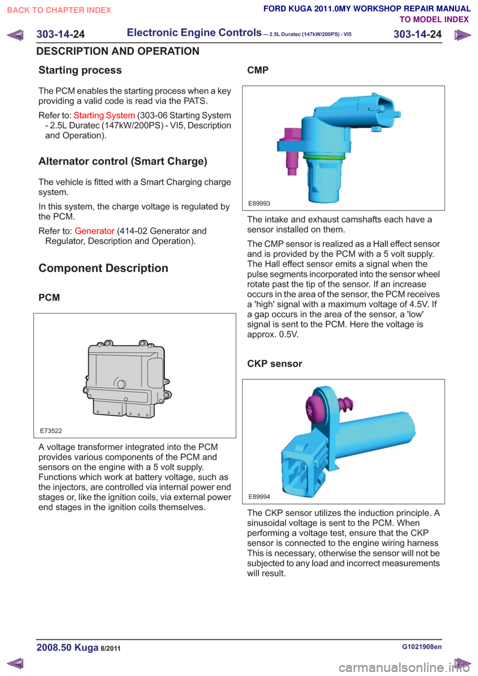
PCM
E73522
A voltage transformer integrated into the PCM
provides various components of the PCM and
sensors on the engine with a 5 volt supply.
Functions which work at battery voltage, such as
the injectors, are controlled via internal power end
stages or, like the ignition coils, via external power
end stages in the ignition coils themselves.
CMP
E89993
The intake and exhaust camshafts each have a
sensor installed on them.
The CMP sensor is realized as a Hall effect sensor
and is provided by the PCM with a 5 volt supply.
The Hall effect sensor emits a signal when the
pulse segments incorporated into the sensor wheel
rotate past the tip of the sensor. If an increase
occurs in the area of the sensor, the PCM receives
a 'high' signal with a maximum voltage of 4.5V. If
a gap occurs in the area of the sensor, a 'low'
signal is sent to the PCM. Here the voltage is
approx. 0.5V.
CKP sensor
E89994
The CKP sensor utilizes the induction principle. A
sinusoidal voltage is sent to the PCM. When
performing a voltage test, ensure that the CKP
sensor is connected to the engine wiring harness
This is necessary, otherwise the sensor will not be
subjected to any load and incorrect measurements
will result.
G1021908en2008.50 Kuga8/2011
303-14- 24
Electronic Engine Controls— 2.5L Duratec (147kW/200PS) - VI5303-14-
24
DESCRIPTION AND OPERATION
TO MODEL INDEX
BACK TO CHAPTER INDEX
FORD KUGA 2011.0MY WORKSHOP REPAIR MANUAL
Page 1809 of 2057
Electronic Engine Controls
General EquipmentFord diagnostic equipment
Inspection and Verification
1. Verify the customer concern.
2. Visually inspect for obvious signs of mechanical or electrical damage.
Visual Inspection Chart
Electrical
– Fuse(s)
– Wiring harness
– Electrical connector(s)
– Relay(s)
– Sensor(s)
– Switch(es)
– Powertrain control module (PCM)
3. If an obvious cause for an observed or reported concern is found, correct the cause (if possible)
before proceeding to the next step
4. If the cause is not visually evident, verify the symptom and refer to the Ford diagnostic
equipment to diagnose the system.
G165604en2008.50 Kuga8/2011
303-14- 35
Electronic Engine Controls— 2.5L Duratec (147kW/200PS) - VI5303-14-
35
DIAGNOSIS AND TESTING
TO MODEL INDEX
BACK TO CHAPTER INDEX
FORD KUGA 2011.0MY WORKSHOP REPAIR MANUAL
Page 1879 of 2057
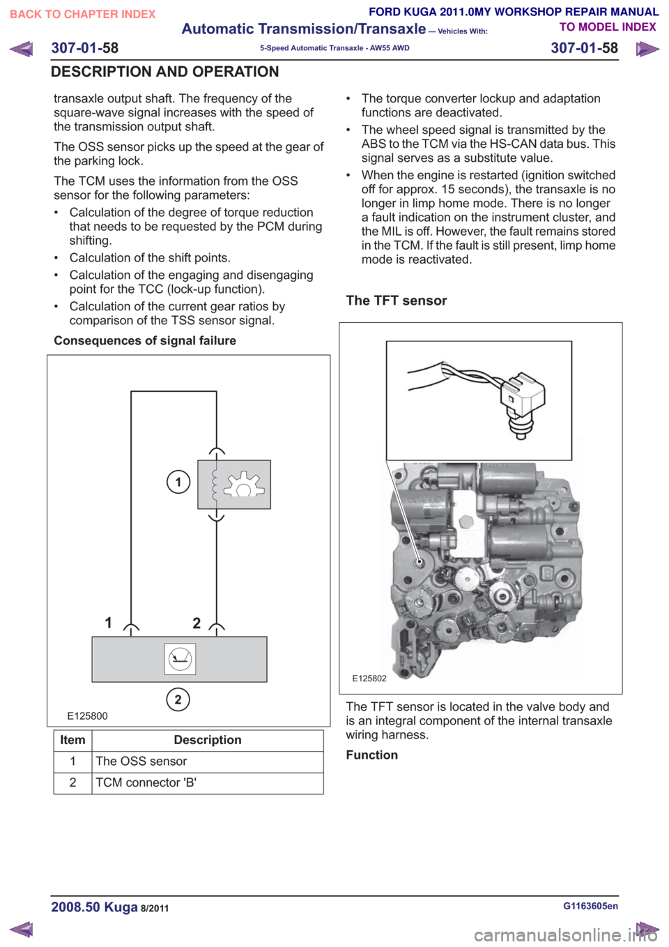
transaxle output shaft. The frequency of the
square-wave signal increases with the speed of
the transmission output shaft.
The OSS sensor picks up the speed at the gear of
the parking lock.
The TCM uses the information from the OSS
sensor for the following parameters:
• Calculation of the degree of torque reductionthat needs to be requested by the PCM during
shifting.
• Calculation of the shift points.
• Calculation of the engaging and disengaging point for the TCC (lock-up function).
• Calculation of the current gear ratios by comparison of the TSS sensor signal.
Consequences of signal failure
E125800
1 2
2
1
Description
Item
The OSS sensor
1
TCM connector 'B'
2 • The torque converter lockup and adaptation
functions are deactivated.
• The wheel speed signal is transmitted by the ABS to the TCM via the HS-CAN data bus. This
signal serves as a substitute value.
• When the engine is restarted (ignition switched off for approx. 15 seconds), the transaxle is no
longer in limp home mode. There is no longer
a fault indication on the instrument cluster, and
the MIL is off. However, the fault remains stored
in the TCM. If the fault is still present, limp home
mode is reactivated.
The TFT sensor
E125802
The TFT sensor is located in the valve body and
is an integral component of the internal transaxle
wiring harness.
Function
G1163605en2008.50 Kuga8/2011
307-01- 58
Automatic Transmission/Transaxle
— Vehicles With:
5-Speed Automatic Transaxle - AW55 AWD
307-01- 58
DESCRIPTION AND OPERATION
TO MODEL INDEX
BACK TO CHAPTER INDEX
FORD KUGA 2011.0MY WORKSHOP REPAIR MANUAL
Page 1970 of 2057
Fuel System — Vehicles With: Fuel Additive Tank
General EquipmentFord diagnostic equipment
Principles of Operation
WARNINGS:
This procedure involves fuel additive
handling. Be prepared for fuel additive
spillage at all times and always observe
fuel handling precautions. Failure to follow
these instructions may result in personal
injury.
Eye, hand, ear protection and protective
clothing are required to be worn during
any general service or removal and
installation service procedure of fuel
additive system components. Failure to
follow this instruction may result in
personal injury.
In case of fuel additive fluid contact with
the skin or the eyes, flush immediately with
water for a minimum of 15 minutes and
seek prompt medical attention. Failure to
follow these instructions may result in
personal injury.
If fuel additive fluid is swallowed, call a
physician immediately. Rinse mouth
immediately with water, do not induce
vomiting. Failure to follow these
instructions may result in personal injury.
Always provide adequate ventilation when
working on the fuel additive fluid system
or related components. Failure to follow
these instructions may result in personal
injury.
Do not smoke or carry lighted tobacco or
open flame of any type when working on
or near any fuel related components.
Highly flammable vapors are always
present and may ignite. Failure to follow
these instructions may result in personal
injury.
CAUTION: Make sure the workshop area
in which the vehicle is being worked on is
as clean and as dust free as possible.
Foreign matter from working on clutches,
brakes or from machining or welding
operations can contaminate the fuel
system and may result in later malfunction. The fuel additive system is an on-board system
that allows the injection of an additive at each
refueling operation by the customer. The additive
quantity is proportional to the fuel quantity that has
been added. The fuel additive system module
controls the amount of additive fluid entering the
fuel tank at each refueling, A switch mounted on
the fuel filler flap is used to detect the start of the
refueling event and the fuel gauge that is mounted
within the fuel tank informs the fuel additive tank
module the quantity of actual fuel added.
Inspection and Verification
1. Verify the customer concern.
2. Visually inspect for obvious signs of leakage
and mechanical or electrical damage.
Visual Inspection Chart
Electrical
Mechanical
– Fuse(s)
– Fuel filler switch andmagnet
– Wiring harness(s)
– Electrical connector(s)
– Fuel additive system module
– Fuel additive tank module
– Instrument cluster
– Powertrain Control Module (PCM)
– Fuel level sensor
– Fuel additive tank
– Fuel additive tank
line(s)
– Fuel additive tank pipe(s)
– Fuel additive tank connector(s)
– Fuel tank filler cap
3. If an obvious cause for an observed or reported concern is found, correct the cause (if possible)
before proceeding to the next step
4. If the cause is not visually evident, REFER to the Ford diagnostic equipment.
G1080718en2008.50 Kuga8/2011
310-00- 2
Fuel System - General Information
310-00- 2
DIAGNOSIS AND TESTING
TO MODEL INDEX
BACK TO CHAPTER INDEX
FORD KUGA 2011.0MY WORKSHOP REPAIR MANUAL
Page 2002 of 2057
Acceleration Control
Inspection and Verification
1. Verify the customer concern.
2. Visually inspect for obvious signs of mechanicalor electrical damage.
Visual Inspection Chart
Electrical
Mechanical
– Wiring harness(s)
– Wiring harnessretaining clips
– Electrical connector(s)
– Accelerator pedal
– Powertrain control module (PCM)
– Electronic throttle body
– Accelerator pedal
– Throttle body
3. If an obvious cause for an observed or reported concern is found, correct the cause (if possible)
before proceeding to the next step.
4. If the cause is not visually evident, verify the symptom and refer to the diagnostic tab within
the Ford approved diagnostic tool.
G1080719en2008.50 Kuga8/2011
310-02- 2
Acceleration Control
310-02- 2
DIAGNOSIS AND TESTING
TO MODEL INDEX
BACK TO CHAPTER INDEX
FORD KUGA 2011.0MY WORKSHOP REPAIR MANUAL