2011 FORD KUGA Manual Temperature Control
[x] Cancel search: Manual Temperature ControlPage 2015 of 2057
• The refrigerant line between the fixed orificetube and the evaporator must be cold from the
point where the fixed orifice tube is installed.
Depending on the weather, the refrigerant line
may also have ice on its surface.
• The refrigerant line between the evaporator and the A/C compressor including the dehydrator
must be cold.
Evaporator outlet line temperature test
To test the power of the A/C system, the
temperature at the evaporator outlet line must be
measured. To do this, the following preconditions
must be met:
• Open all windows.
• Set the air distribution to the defrost/dashboardposition and open all the ventilation nozzles.
• DO NOT switch on recirculated air.
• Select lowest blower switch setting.
• Select lowest temperature setting.
NOTE: The temperature measurement cannot be
done with a thermometer which makes no contact.
The surface reflection from the metal line may
cause incorrect readings.
Connect the temperature sensor (Fluke 80 PK-8)
to the outlet line of the evaporator. Locate the
temperature sensor as close as possible to the
evaporator. Connect the temperature sensor to the
multimeter.
Start the engine and allow it to run at idle speed
for several minutes.
Switch on the A/C.
After three minutes, measure the surface
temperature of the evaporator outlet line.
If the temperature measured is 4° C or lower, the
A/C system is OK. If the temperature is higher, the
A/C system may be under-filled. For further
information, refer to
REFER to: Air Conditioning (A/C) System
Recovery, Evacuation and Charging (412-00
Climate Control System - General Information,
General Procedures).
Frequent faults and their causes
If the cooling power of the A/C system is not
adequate, make certain that the temperature
control flap(s) is/are operating correctly. • No or poor cooling performance:
– Blockage or narrowing of a refrigerant line orin the dehydrator. The location of the
blockage or narrowing can easily be located
by temperature comparisons at the
refrigerant lines and the dehydrator. The
blockage or restriction is located at the point
where the temperature difference is
identified. Note: A temperature difference
in the area of the fixed orifice tube is
normal. If the location of the blockage or
narrowing is found, check the corresponding
component and renew as applicable.
• Sudden drop in cooling performance (after the air conditioning has been switched off for
approx. 5 minutes, the cooling performance
returns to normal):
– The cause is an iced-up fixed orifice tubebecause of moisture in the refrigerant circuit.
In order to ensure that moisture is completely
removed from the refrigerant circuit, the
dehydrator should be renewed and the
evacuation time should be extended to 2-3
hours. For further information
REFER to: Air Conditioning (A/C) System
Recovery, Evacuation and Charging
(412-00 Climate Control System - General
Information, General Procedures).
Sequence of A/C Request Signal
NOTE: The electronic automatic temperature
control (EATC) module is integrated into the air
conditioning control assembly.
NOTE: The generic electronic module (GEM) is
an integral part of the central junction box (CJB).
After actuating the A/C ON/OFF switch integrated
into the A/C control assembly, an A/C request
signal is sent from the A/C control assembly
(vehicles with EATC: EATC module) to the GEM.
From there, the signal is sent to the instrument
cluster via the MS-CAN bus. A gateway is installed
in the instrument cluster, which establishes the
connection between the MS-CAN bus and the
HS-CAN bus.
After the signal has been converted in the gateway,
it is relayed to the powertrain control module (PCM)
via the HS-CAN bus. Once all the required
parameters have been met, the PCM switches on
the refrigerant compressor and thus the A/C system
via the A/C clutch relay.
G1055878en2008.50 Kuga8/2011
412-00- 4
Climate Control System - General Information
412-00- 4
DIAGNOSIS AND TESTING
TO MODEL INDEX
BACK TO CHAPTER INDEX
FORD KUGA 2011.0MY WORKSHOP REPAIR MANUAL
Page 2028 of 2057
SECTION 412-01 Climate Control
VEHICLE APPLICATION:2008.50 Kuga
PA G E
CONTENTS
SPECIFICATIONS
412-01-3
Specifications ........................................................................\
..............................................
DESCRIPTION AND OPERATION 412-01-4
Climate Control (Component Location) ........................................................................\
......
412-01-10
Climate Control (Overview) ........................................................................\
........................
412-01-10
Pollen filter ........................................................................\
..................................................
412-01-10
Heat exchanger ........................................................................\
..........................................
412-01-10
Evaporator assembly ........................................................................\
..................................
412-01-10
Blower motor ........................................................................\
..............................................
412-01-11
Fault Memory Interrogation without diagnostics unit - vehicles with automatic temperature
control ........................................................................\
.......................................................
412-01-11
Switch over from Celsius to Fahrenheit ........................................................................\
......
412-01-12
Climate Control (System Operation and Component Description) .....................................
412-01-12
System Diagram ........................................................................\
.........................................
412-01-19
System Operation ........................................................................\
.......................................
412-01-19
Climate control housing ........................................................................\
..........................
412-01-22
Climate control ........................................................................\
........................................
412-01-24
Component Description ........................................................................\
..............................
412-01-24
Air conditioning compressor ........................................................................\
...................
412-01-24
Pollen filter ........................................................................\
..............................................
412-01-24
Control assembly, climate control - vehicles with manual temperature control ..............
412-01-25
Control assembly, climate control - vehicles with automatic temperature control ...........
412-01-25
Control assembly, climate control - vehicles with DVD navigation system with a touch
screen........................................................................\
................................................... 412-01-25
Climate control module - vehicles with DVD navigation system with a touch screen.....
412-01-25
Sun sensor - vehicles with automatic temperature control .............................................
412-01-26
In-vehicle temperature sensor ........................................................................\
................
412-01-26
Ambient temperature sensor ........................................................................\
..................
412-01-26
Blower motor ........................................................................\
...........................................
412-01-26
Blower control module - vehicles equipped with automatic temperature control ............
REMOVAL AND INSTALLATION 412-01-28
(34 626 4)
Air Conditioning (A/C) Compressor — 2.5L Duratec (147kW/200PS) - VI5 ....
412-01-29
Air Conditioning (A/C) Compressor to Condenser Discharge Line .....................................
412-01-30
Air Conditioning (A/C) Compressor to Condenser Discharge Line — 2.5L Duratec
(147kW/200PS) - VI5 ........................................................................\
................................
412-01-31
Condenser ........................................................................\
..................................................
412-01-35
Clutch and Clutch Field Coil........................................................................\
.......................
412-01-36
Pollen Filter — RHD........................................................................\
...................................
412-01-37
(34
374 0)
Blower Motor — RHD ........................................................................\
.............
412-01-40
(34 382 0)
Blower Motor Resistor — Vehicles With: Manual Temperature Control, RHD .
412-01-41
(34 382 0)
Blower Motor Resistor — Vehicles With: Dual Automatic Temperature
Control ........................................................................\
..................................
412-01- 1
Climate Control
412-01- 1
.
TO MODEL INDEX
BACK TO CHAPTER INDEX
PAGE 1 OF 2 FORD KUGA 2011.0MY WORKSHOP REPAIR MANUAL
Page 2029 of 2057

412-01-42
Heater Core and Evaporator Core Housing .......................................................................
412-01-45
(34 364 0)
Heater Core — RHD ........................................................................\
...............
412-01-53
Suction Accumulator ........................................................................\
...................................
412-01-56
Suction Accumulator to Air Conditioning (A/C) Compressor Line ......................................
412-01-57
Suction Accumulator to Air Conditioning (A/C) Compressor Line — 2.5L Duratec
(147kW/200PS) - VI5 ........................................................................\
................................
412-01-58
Low-Pressure Cutoff Switch ........................................................................\
.......................
412-01-59
High-Pressure Cutoff Switch ........................................................................\
.......................
412-01-60
Evaporator ........................................................................\
..................................................
412-01-62
Evaporator Outlet Line ........................................................................\
................................
412-01-65
Evaporator Core Orifice ........................................................................\
..............................
412-01-68
Condenser to Evaporator Line........................................................................\
....................
412-01-71
(34 300 0)
Climate Control Assembly — Vehicles With: Manual Temperature Control ....
412-01-72
(34 300 0)
Climate Control Assembly — Vehicles With: Automatic Temperature Control .
412-01-73
(34 485 4)
Footwell Air Discharge Temperature Sensor ..................................................
412-01-74
Center Register Air Discharge Temperature Sensor ..........................................................
412-01-75
In-Vehicle Temperature Sensor ........................................................................\
..................
412-01-76
(34 676 0)
Ambient Air Temperature Sensor ...................................................................
412-01-77
(34 665 0)
Sunload Sensor ........................................................................\
......................
412-01-78
(34 591 0)
Footwell Vent/Duct Blend Door Actuator — RHD ...........................................
412-01-79
(34 606 0)
Air Inlet Blend Door Actuator ........................................................................\
..
412-01-80
(34 608 0)
Driver Side Temperature Blend Door Actuator ...............................................
412-01-81
(34 608 0)
Passenger Side Temperature Blend Door Actuator .......................................
412-01-82
(34 591 0)
Defrost Vent/Register Blend Door Actuator — RHD ......................................
412-01-2
Climate Control
412-01- 2
.
TO MODEL INDEX
BACK TO CHAPTER INDEX
PAGE 2 OF 2 FORD KUGA 2011.0MY WORKSHOP REPAIR MANUAL
Page 2032 of 2057
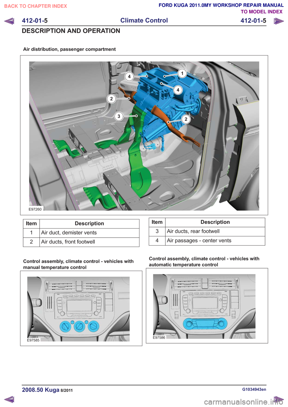
Air distribution, passenger compartment
E97260
14
2
2
3
4
Description
Item
Air duct, demister vents
1
Air ducts, front footwell
2Description
Item
Air ducts, rear footwell
3
Air passages - center vents
4
Control assembly, climate control - vehicles with
manual temperature control
E97585
Control assembly, climate control - vehicles with
automatic temperature control
E97586
G1034943en2008.50 Kuga8/2011
412-01- 5
Climate Control
412-01- 5
DESCRIPTION AND OPERATION
TO MODEL INDEX
BACK TO CHAPTER INDEX
FORD KUGA 2011.0MY WORKSHOP REPAIR MANUAL
Page 2033 of 2057
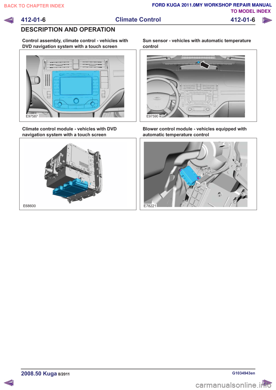
Control assembly, climate control - vehicles with
DVD navigation system with a touch screen
E97587
Climate control module - vehicles with DVD
navigation system with a touch screen
E68600
Sun sensor - vehicles with automatic temperature
control
E97590
Blower control module - vehicles equipped with
automatic temperature control
E78221
G1034943en2008.50 Kuga8/2011
412-01-6
Climate Control
412-01- 6
DESCRIPTION AND OPERATION
TO MODEL INDEX
BACK TO CHAPTER INDEX
FORD KUGA 2011.0MY WORKSHOP REPAIR MANUAL
Page 2035 of 2057
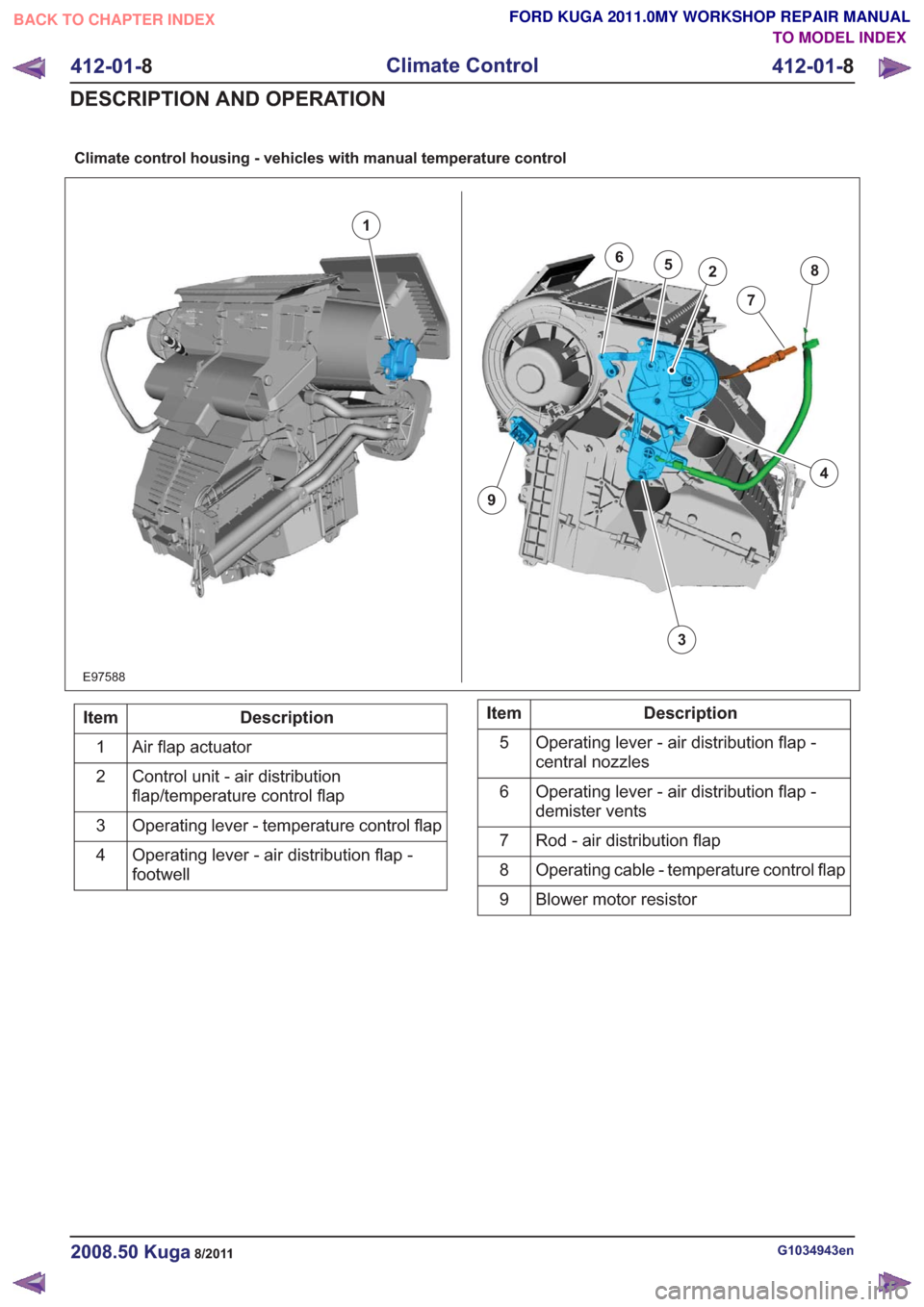
Climate control housing - vehicles with manual temperature control
E97588
1
7
3
862
4
9
5
Description
Item
Air flap actuator
1
Control unit - air distribution
flap/temperature control flap
2
Operating lever - temperature control flap
3
Operating lever - air distribution flap -
footwell
4Description
Item
Operating lever - air distribution flap -
central nozzles
5
Operating lever - air distribution flap -
demister vents
6
Rod - air distribution flap
7
Operating cable - temperature control flap
8
Blower motor resistor
9
G1034943en2008.50 Kuga8/2011
412-01- 8
Climate Control
412-01- 8
DESCRIPTION AND OPERATION
TO MODEL INDEX
BACK TO CHAPTER INDEX
FORD KUGA 2011.0MY WORKSHOP REPAIR MANUAL
Page 2036 of 2057
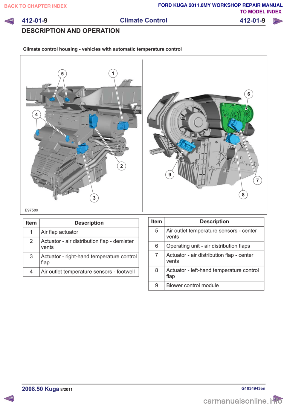
Climate control housing - vehicles with automatic temperature control
E97589
1
7
6
38
9
5
4
2
Description
Item
Air flap actuator
1
Actuator - air distribution flap - demister
vents
2
Actuator - right-hand temperature control
flap
3
Air outlet temperature sensors - footwell
4Description
Item
Air outlet temperature sensors - center
vents
5
Operating unit - air distribution flaps
6
Actuator - air distribution flap - center
vents
7
Actuator - left-hand temperature control
flap
8
Blower control module
9
G1034943en2008.50 Kuga8/2011
412-01- 9
Climate Control
412-01- 9
DESCRIPTION AND OPERATION
TO MODEL INDEX
BACK TO CHAPTER INDEX
FORD KUGA 2011.0MY WORKSHOP REPAIR MANUAL
Page 2038 of 2057
Fault Memory Interrogation without
diagnostics unit - vehicles with
automatic temperature control
NOTE:On vehicles equipped with a DVD
navigation system with touchscreen, the fault
memory can only be interrogated using the Ford
diagnostic tool.
The climate control and heating system features
a on-board diagnosis function which can detect
and store both current permanent faults as well as
intermittent faults which have occurred during
normal operation of the vehicle. It is also possible
to read out these faults via the display on the
control panel of the climate control system. To read
out the fault memory, the ignition key must be
turned to the "ON" position and the battery voltage
must be between 9 V and 16 V.
To activate the on-board diagnosis at the control
panel for the climate control system, PRESS the
"OFF" and "FOOTWELL" buttons simultaneously
for exactly 2 seconds, then PRESS "AUTO" within
1.5 seconds. The on-board diagnosis which then
starts lasts a few seconds. An animated display
appears in the display of the control panel for the
climate control system during this time. Any faults
found are displayed on both displays of the control
panel for the climate control system in the form of
trouble codes.
To read out saved errors at the control panel for
the climate control system, PRESS the "OFF" and
"FOOTWELL" buttons simultaneously for exactly
2 seconds, then PRESS "HEAD AREA" within 1.5
seconds. Any stored faults are shown on the
display of the control panel for the climate control
system and should be noted for safety reasons.
By PRESSING the "DEFROST" button, the fault
memory is cleared and diagnosis mode is ended.
To end the diagnostic mode without clearing the
DTCs, PRESS any other operating button on the
control panel for the climate control system.
To read out the software version at the control
panel for the climate control system, PRESS the
"OFF" and "FOOTWELL" buttons simultaneously
for exactly 2 seconds, then PRESS "A/C" within
1.5 seconds. The software version is shown on the
display of the control panel for the climate control
system. The output mode can be exited by
PRESSING any button on the control panel for the
climate control system.
Switch over from Celsius to Fahrenheit
The switch from Celsius to Fahrenheit is performed
on the display of the instrument cluster and is then
transmitted via the CAN bus to the module of the
two-zone air conditioning system.
G1034945en2008.50 Kuga8/2011
412-01- 11
Climate Control
412-01- 11
DESCRIPTION AND OPERATION
TO MODEL INDEX
BACK TO CHAPTER INDEX
FORD KUGA 2011.0MY WORKSHOP REPAIR MANUAL