2011 FORD KUGA ignition
[x] Cancel search: ignitionPage 1447 of 2057
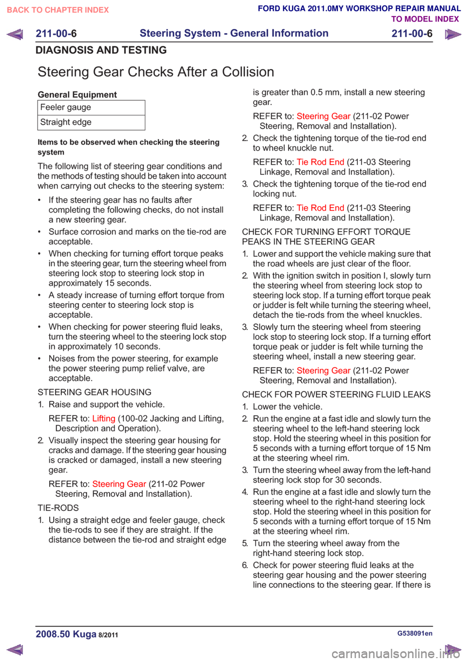
Steering Gear Checks After a Collision
General EquipmentFeeler gauge
Straight edge
Items to be observed when checking the steering
system
The following list of steering gear conditions and
the methods of testing should be taken into account
when carrying out checks to the steering system:
• If the steering gear has no faults after completing the following checks, do not install
a new steering gear.
• Surface corrosion and marks on the tie-rod are acceptable.
• When checking for turning effort torque peaks in the steering gear, turn the steering wheel from
steering lock stop to steering lock stop in
approximately 15 seconds.
• A steady increase of turning effort torque from steering center to steering lock stop is
acceptable.
• When checking for power steering fluid leaks, turn the steering wheel to the steering lock stop
in approximately 10 seconds.
• Noises from the power steering, for example the power steering pump relief valve, are
acceptable.
STEERING GEAR HOUSING
1. Raise and support the vehicle. REFER to: Lifting(100-02 Jacking and Lifting,
Description and Operation).
2. Visually inspect the steering gear housing for cracks and damage. If the steering gear housing
is cracked or damaged, install a new steering
gear.
REFER to: Steering Gear (211-02 Power
Steering, Removal and Installation).
TIE-RODS
1. Using a straight edge and feeler gauge, check the tie-rods to see if they are straight. If the
distance between the tie-rod and straight edge is greater than 0.5 mm, install a new steering
gear.
REFER to:
Steering Gear (211-02 Power
Steering, Removal and Installation).
2. Check the tightening torque of the tie-rod end to wheel knuckle nut.
REFER to: Tie Rod End (211-03 Steering
Linkage, Removal and Installation).
3. Check the tightening torque of the tie-rod end locking nut.
REFER to: Tie Rod End (211-03 Steering
Linkage, Removal and Installation).
CHECK FOR TURNING EFFORT TORQUE
PEAKS IN THE STEERING GEAR
1. Lower and support the vehicle making sure that the road wheels are just clear of the floor.
2. With the ignition switch in position I, slowly turn the steering wheel from steering lock stop to
steering lock stop. If a turning effort torque peak
or judder is felt while turning the steering wheel,
detach the tie-rods from the wheel knuckles.
3. Slowly turn the steering wheel from steering lock stop to steering lock stop. If a turning effort
torque peak or judder is felt while turning the
steering wheel, install a new steering gear.
REFER to: Steering Gear (211-02 Power
Steering, Removal and Installation).
CHECK FOR POWER STEERING FLUID LEAKS
1. Lower the vehicle.
2. Run the engine at a fast idle and slowly turn the steering wheel to the left-hand steering lock
stop. Hold the steering wheel in this position for
5 seconds with a turning effort torque of 15 Nm
at the steering wheel rim.
3. Turn the steering wheel away from the left-hand steering lock stop for 30 seconds.
4. Run the engine at a fast idle and slowly turn the steering wheel to the right-hand steering lock
stop. Hold the steering wheel in this position for
5 seconds with a turning effort torque of 15 Nm
at the steering wheel rim.
5. Turn the steering wheel away from the right-hand steering lock stop.
6. Check for power steering fluid leaks at the steering gear housing and the power steering
line connections to the steering gear. If there is
G538091en2008.50 Kuga8/2011
211-00- 6
Steering System - General Information
211-00- 6
DIAGNOSIS AND TESTING
TO MODEL INDEX
BACK TO CHAPTER INDEX
FORD KUGA 2011.0MY WORKSHOP REPAIR MANUAL
Page 1465 of 2057
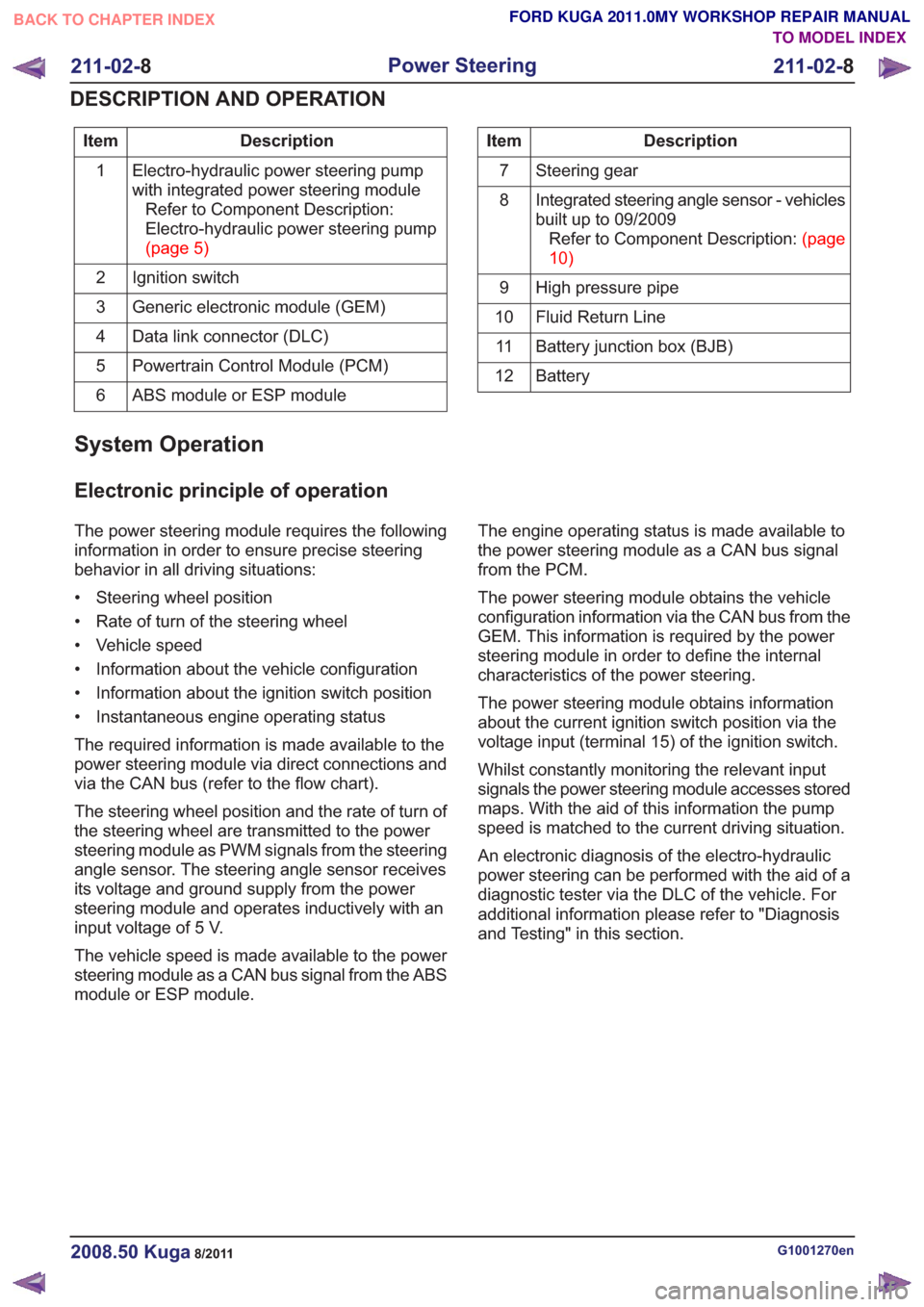
Description
Item
Electro-hydraulic power steering pump
with integrated power steering moduleRefer to Component Description:
Electro-hydraulic power steering pump
(page5)
1
Ignition switch
2
Generic electronic module (GEM)
3
Data link connector (DLC)
4
Powertrain Control Module (PCM)
5
ABS module or ESP module
6Description
Item
Steering gear
7
Integrated steering angle sensor - vehicles
built up to 09/2009RefertoComponentDescription:(page
10)
8
High pressure pipe
9
Fluid Return Line
10
Battery junction box (BJB)
11
Battery
12
System Operation
Electronic principle of operation
The power steering module requires the following
information in order to ensure precise steering
behavior in all driving situations:
• Steering wheel position
• Rate of turn of the steering wheel
• Vehicle speed
• Information about the vehicle configuration
• Information about the ignition switch position
• Instantaneous engine operating status
The required information is made available to the
power steering module via direct connections and
via the CAN bus (refer to the flow chart).
The steering wheel position and the rate of turn of
the steering wheel are transmitted to the power
steering module as PWM signals from the steering
angle sensor. The steering angle sensor receives
its voltage and ground supply from the power
steering module and operates inductively with an
input voltage of 5 V.
The vehicle speed is made available to the power
steering module as a CAN bus signal from the ABS
module or ESP module. The engine operating status is made available to
the power steering module as a CAN bus signal
from the PCM.
The power steering module obtains the vehicle
configuration information via the CAN bus from the
GEM. This information is required by the power
steering module in order to define the internal
characteristics of the power steering.
The power steering module obtains information
about the current ignition switch position via the
voltage input (terminal 15) of the ignition switch.
Whilst constantly monitoring the relevant input
signals the power steering module accesses stored
maps. With the aid of this information the pump
speed is matched to the current driving situation.
An electronic diagnosis of the electro-hydraulic
power steering can be performed with the aid of a
diagnostic tester via the DLC of the vehicle. For
additional information please refer to "Diagnosis
and Testing" in this section.
G1001270en2008.50 Kuga8/2011
211-02-
8
Power Steering
211-02- 8
DESCRIPTION AND OPERATION
TO MODEL INDEX
BACK TO CHAPTER INDEX
FORD KUGA 2011.0MY WORKSHOP REPAIR MANUAL
Page 1521 of 2057
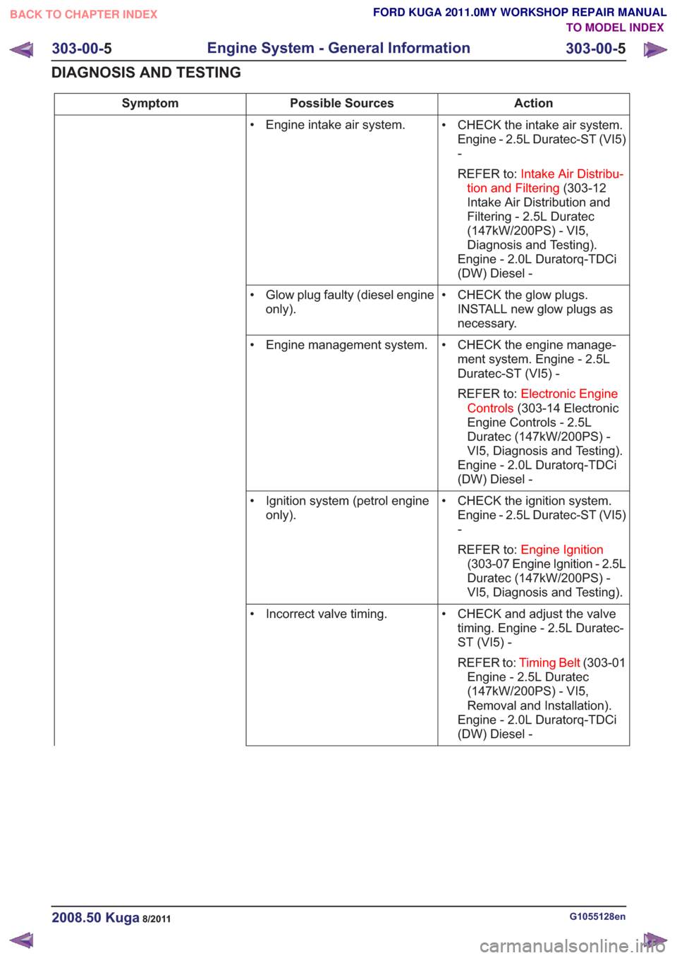
Action
Possible Sources
Symptom
• CHECK the intake air system.Engine - 2.5L Duratec-ST (VI5)
-
REFER to: Intake Air Distribu-
tion and Filtering (303-12
Intake Air Distribution and
Filtering - 2.5L Duratec
(147kW/200PS) - VI5,
Diagnosis and Testing).
Engine - 2.0L Duratorq-TDCi
(DW) Diesel -
• Engine intake air system.
• CHECK the glow plugs.INSTALL new glow plugs as
necessary.
• Glow plug faulty (diesel engine
only).
• CHECK the engine manage-ment system. Engine - 2.5L
Duratec-ST (VI5) -
REFER to: Electronic Engine
Controls (303-14 Electronic
Engine Controls - 2.5L
Duratec (147kW/200PS) -
VI5, Diagnosis and Testing).
Engine - 2.0L Duratorq-TDCi
(DW) Diesel -
• Engine management system.
• CHECK the ignition system.Engine - 2.5L Duratec-ST (VI5)
-
REFER to: Engine Ignition
(303-07 Engine Ignition - 2.5L
Duratec (147kW/200PS) -
VI5, Diagnosis and Testing).
• Ignition system (petrol engine
only).
• CHECK and adjust the valvetiming. Engine - 2.5L Duratec-
ST (VI5) -
REFER to: Timing Belt (303-01
Engine - 2.5L Duratec
(147kW/200PS) - VI5,
Removal and Installation).
Engine - 2.0L Duratorq-TDCi
(DW) Diesel -
• Incorrect valve timing.
G1055128en2008.50 Kuga8/2011
303-00-
5
Engine System - General Information
303-00- 5
DIAGNOSIS AND TESTING
TO MODEL INDEX
BACK TO CHAPTER INDEX
FORD KUGA 2011.0MY WORKSHOP REPAIR MANUAL
Page 1523 of 2057
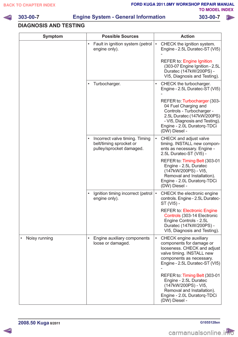
Action
Possible Sources
Symptom
• CHECK the ignition system.Engine - 2.5L Duratec-ST (VI5)
-
REFER to: Engine Ignition
(303-07 Engine Ignition - 2.5L
Duratec (147kW/200PS) -
VI5, Diagnosis and Testing).
• Fault in ignition system (petrol
engine only).
• CHECK the turbocharger.Engine - 2.5L Duratec-ST (VI5)
-
REFER to: Turbocharger (303-
04 Fuel Charging and
Controls - Turbocharger -
2.5L Duratec (147kW/200PS)
- VI5, Diagnosis and Testing).
Engine - 2.0L Duratorq-TDCi
(DW) Diesel -
• Turbocharger.
• CHECK and adjust valvetiming. INSTALL new compon-
ents as necessary. Engine -
2.5L Duratec-ST (VI5) -
REFER to: Timing Belt (303-01
Engine - 2.5L Duratec
(147kW/200PS) - VI5,
Removal and Installation).
Engine - 2.0L Duratorq-TDCi
(DW) Diesel -
• Incorrect valve timing. Timing
belt/timing sprocket or
pulley/sprocket damaged.
• CHECK the electronic enginecontrols. Engine - 2.5L Duratec-
ST (VI5) -
REFER to: Electronic Engine
Controls (303-14 Electronic
Engine Controls - 2.5L
Duratec (147kW/200PS) -
VI5, Diagnosis and Testing).
• Ignition timing incorrect (petrol
engine only).
• CHECK engine auxiliarycomponents for damage or
looseness. CHECK and adjust
valve timing. INSTALL new
components as necessary.
Engine - 2.5L Duratec-ST (VI5)
-
REFER to: Timing Belt (303-01
Engine - 2.5L Duratec
(147kW/200PS) - VI5,
Removal and Installation).
Engine - 2.0L Duratorq-TDCi
(DW) Diesel -
• Engine auxiliary components
loose or damaged.
• Noisy running
G1055128en2008.50 Kuga8/2011
303-00-
7
Engine System - General Information
303-00- 7
DIAGNOSIS AND TESTING
TO MODEL INDEX
BACK TO CHAPTER INDEX
FORD KUGA 2011.0MY WORKSHOP REPAIR MANUAL
Page 1526 of 2057
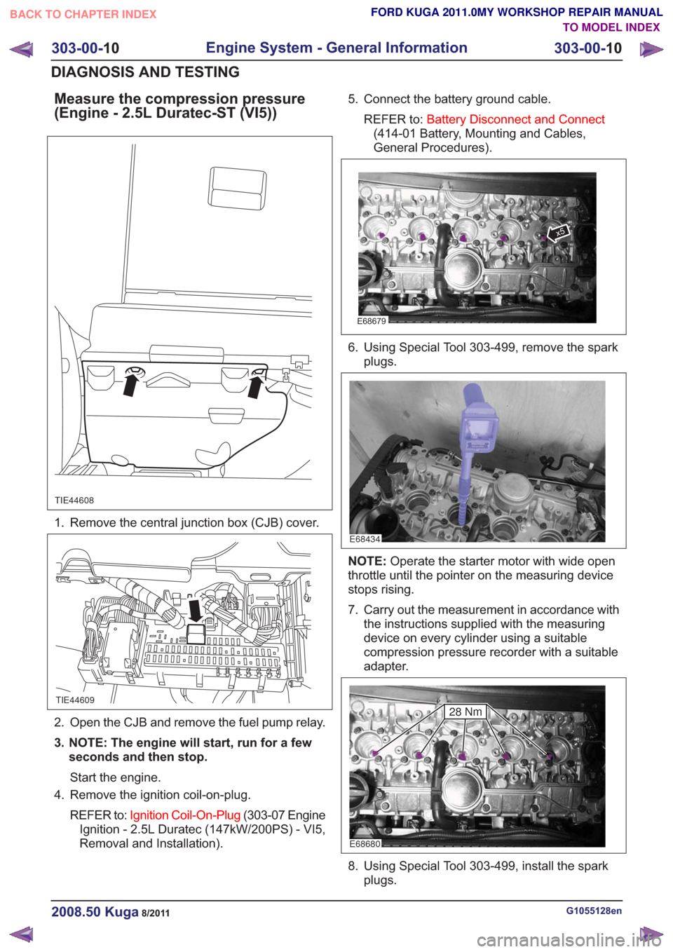
Measure the compression pressure
(Engine - 2.5L Duratec-ST (VI5))
TIE44608
1. Remove the central junction box (CJB) cover.
TIE44609
2. Open the CJB and remove the fuel pump relay.
3. NOTE: The engine will start, run for a fewseconds and then stop.
Start the engine.
4. Remove the ignition coil-on-plug.
REFER to: Ignition Coil-On-Plug (303-07 Engine
Ignition - 2.5L Duratec (147kW/200PS) - VI5,
Removal and Installation). 5. Connect the battery ground cable.
REFER to: Battery Disconnect and Connect
(414-01 Battery, Mounting and Cables,
General Procedures).
E68679
x5
6. Using Special Tool 303-499, remove the spark plugs.
E68434
NOTE: Operate the starter motor with wide open
throttle until the pointer on the measuring device
stops rising.
7. Carry out the measurement in accordance with the instructions supplied with the measuring
device on every cylinder using a suitable
compression pressure recorder with a suitable
adapter.
E68680
28 Nm
8. Using Special Tool 303-499, install the sparkplugs.
G1055128en2008.50 Kuga8/2011
303-00- 10
Engine System - General Information
303-00- 10
DIAGNOSIS AND TESTING
TO MODEL INDEX
BACK TO CHAPTER INDEX
FORD KUGA 2011.0MY WORKSHOP REPAIR MANUAL
Page 1527 of 2057
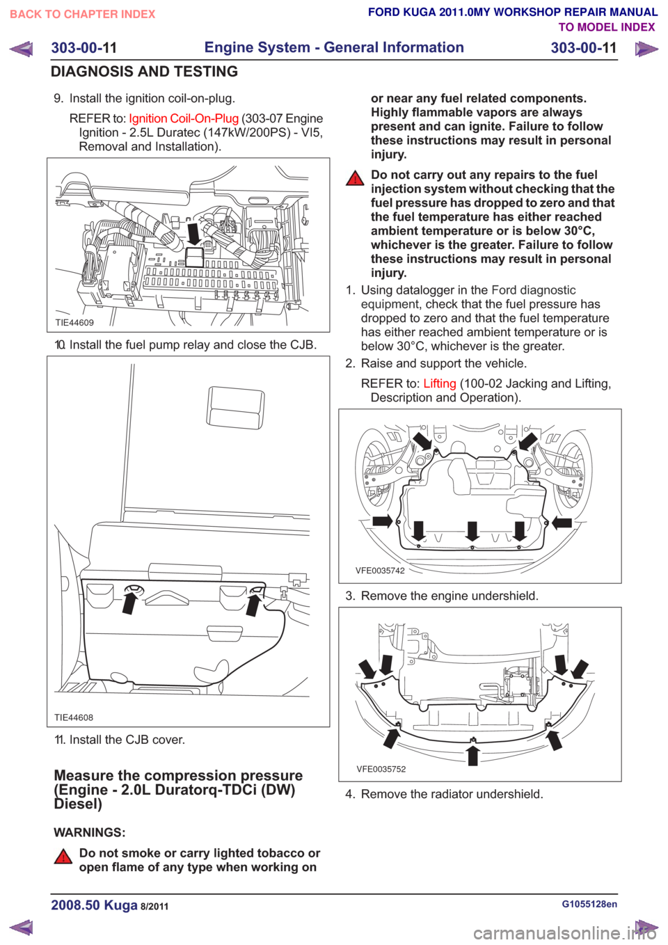
9. Install the ignition coil-on-plug.REFER to: Ignition Coil-On-Plug (303-07 Engine
Ignition - 2.5L Duratec (147kW/200PS) - VI5,
Removal and Installation).
TIE44609
10. Install the fuel pump relay and close the CJB.
TIE44608
11. Install the CJB cover.
Measure the compression pressure
(Engine - 2.0L Duratorq-TDCi (DW)
Diesel)
WARNINGS:
Do not smoke or carry lighted tobacco or
open flame of any type when working on or near any fuel related components.
Highly flammable vapors are always
present and can ignite. Failure to follow
these instructions may result in personal
injury.
Do not carry out any repairs to the fuel
injection system without checking that the
fuel pressure has dropped to zero and that
the fuel temperature has either reached
ambient temperature or is below 30°C,
whichever is the greater. Failure to follow
these instructions may result in personal
injury.
1. Using datalogger in the Ford diagnostic
equipment , check that the fuel pressure has
dropped to zero and that the fuel temperature
has either reached ambient temperature or is
below 30°C, whichever is the greater.
2. Raise and support the vehicle.
REFER to: Lifting(100-02 Jacking and Lifting,
Description and Operation).
VFE0035742
3. Remove the engine undershield.
VFE0035752
4. Remove the radiator undershield.
G1055128en2008.50 Kuga8/2011
303-00- 11
Engine System - General Information
303-00- 11
DIAGNOSIS AND TESTING
TO MODEL INDEX
BACK TO CHAPTER INDEX
FORD KUGA 2011.0MY WORKSHOP REPAIR MANUAL
Page 1569 of 2057
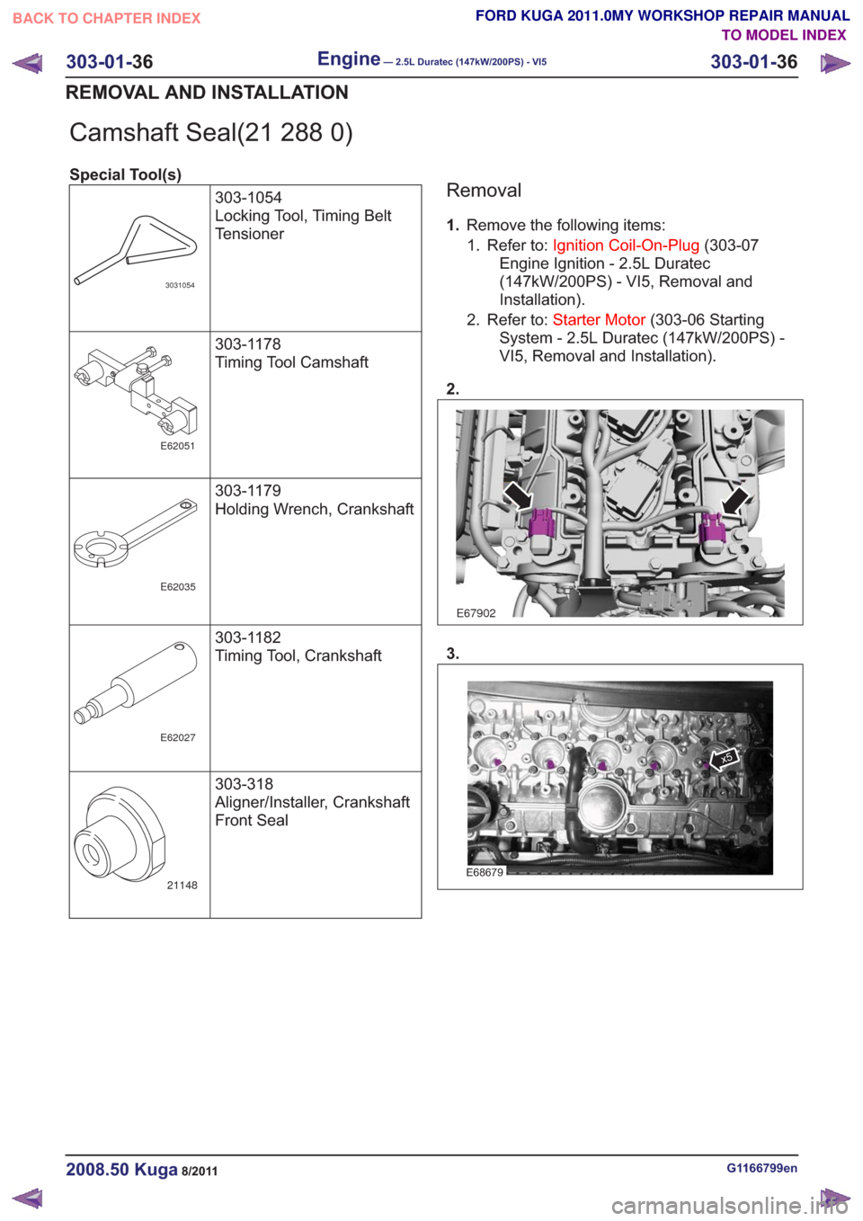
Camshaft Seal(21 288 0)
Special Tool(s)303-1054
Locking Tool, Timing Belt
Tensioner
3031054
303-1178
Timing Tool Camshaft
E62051
303-1179
Holding Wrench, Crankshaft
E62035
303-1182
Timing Tool, Crankshaft
E62027
303-318
Aligner/Installer, Crankshaft
Front Seal
21148
Removal
1.Remove the following items:
1. Refer to: Ignition Coil-On-Plug (303-07
Engine Ignition - 2.5L Duratec
(147kW/200PS) - VI5, Removal and
Installation).
2. Refer to: Starter Motor (303-06 Starting
System - 2.5L Duratec (147kW/200PS) -
VI5, Removal and Installation).
2.
E67902
3.
E68679
x5
G1166799en2008.50 Kuga8/2011
303-01- 36
Engine— 2.5L Duratec (147kW/200PS) - VI5303-01-
36
REMOVAL AND INSTALLATION
TO MODEL INDEX
BACK TO CHAPTER INDEX
FORD KUGA 2011.0MY WORKSHOP REPAIR MANUAL
Page 1576 of 2057
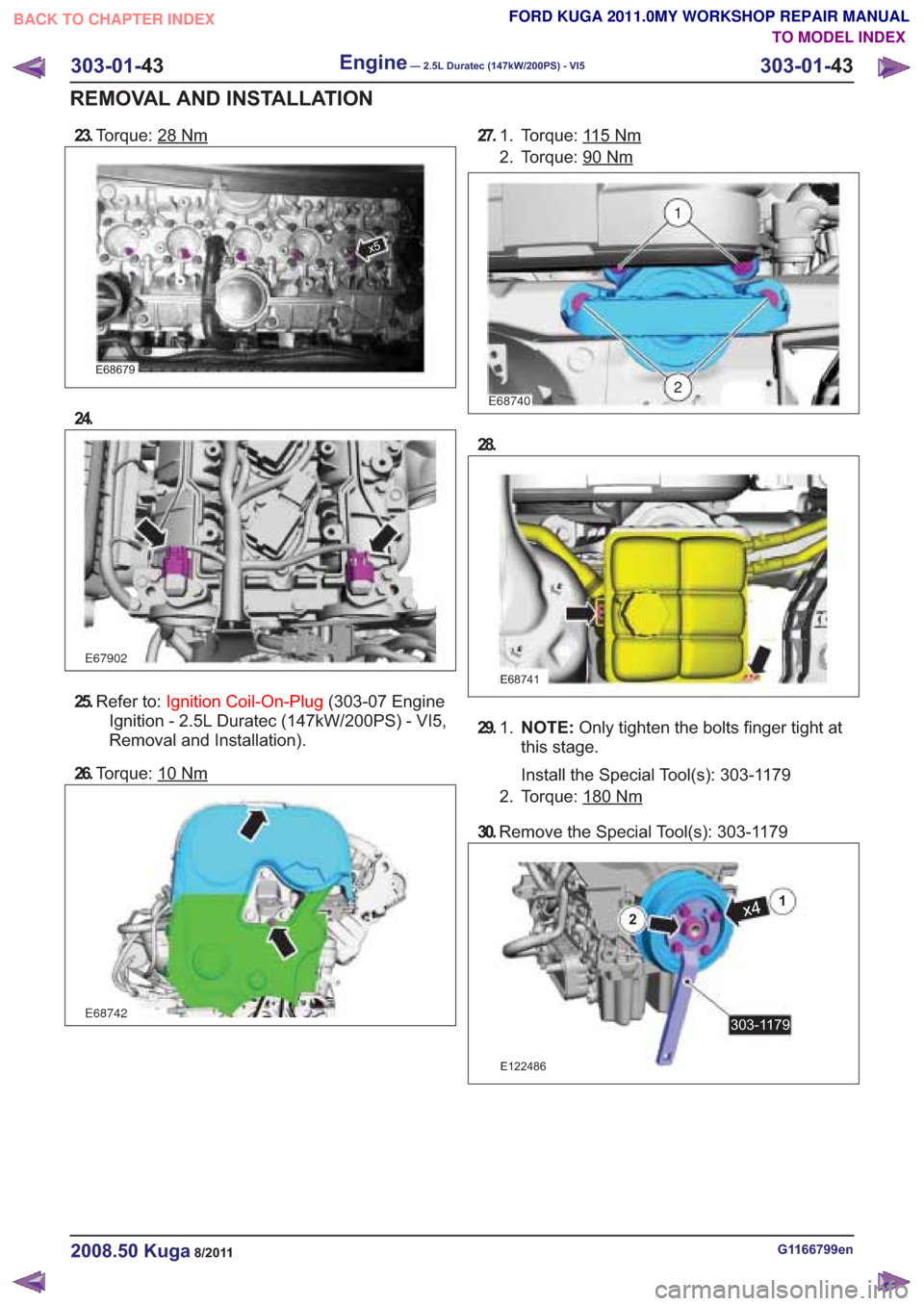
23.Torque: 28Nm
x5
24.
25.Refer to: Ignition Coil-On-Plug (303-07 Engine
Ignition - 2.5L Duratec (147kW/200PS) - VI5,
Removal and Installation).
26. Torque: 10
E68742
27. To r q u e : 115Nm1.
2. Torque: 90
Nm
E68740
1
2
28.
E68741
29. N O T E : Only tighten the bolts finger tight at
this stage.
Install the Special Tool(s): 303-1179
1.
2. Torque: 180
30.
Remove the Special Tool(s): 303-1179
E122486
x41
2
303-1179
G1166799en2008.50 Kuga8/2011
303-01- 43
Engine— 2.5L Duratec (147kW/200PS) - VI5303-01-
43
REMOVAL AND INSTALLATION
TO MODEL INDEX
BACK TO CHAPTER INDEX
FORD KUGA 2011.0MY WORKSHOP REPAIR MANUAL
E68679
E67902
Nm
Nm