Page 1742 of 2057
Accessory Drive Belt(21 567 0)
Removal
1.Remove the air conditioning (A/C) compressor
belt.
Refer to: Air Conditioning (A/C) Compressor
Belt (303-05 Accessory Drive - 2.5L Duratec
(147kW/200PS) - VI5, Removal and
Installation).
2.
E64287
2
1
Installation
1. To install, reverse the removal procedure.
G543728en2008.50 Kuga8/2011
303-05- 12
Accessory Drive— 2.5L Duratec (147kW/200PS) - VI5303-05-
12
REMOVAL AND INSTALLATION
TO MODEL INDEX
BACK TO CHAPTER INDEX
FORD KUGA 2011.0MY WORKSHOP REPAIR MANUAL
Page 1743 of 2057
Air Conditioning (A/C) Compressor Belt(21 567 0)
Removal
1.Remove the right-hand front wheel and tire.
Refer to: Wheel and Tire (204-04 Wheels and
Tires, Removal and Installation).
2.
E65955
3.
E64285
4.
E64286
2
1
Installation
1. To install, reverse the removal procedure.
G545010en2008.50 Kuga8/2011
303-05- 13
Accessory Drive— 2.5L Duratec (147kW/200PS) - VI5303-05-
13
REMOVAL AND INSTALLATION
TO MODEL INDEX
BACK TO CHAPTER INDEX
FORD KUGA 2011.0MY WORKSHOP REPAIR MANUAL
Page 1744 of 2057
Air Conditioning (A/C) Compressor Belt Tensioner
Removal
NOTE:Removal steps in this procedure may
contain installation details.
1. Remove AC compressor belt.
Refer to: Air Conditioning (A/C) Compressor
Belt (303-05 Accessory Drive - 2.5L Duratec
(147kW/200PS) - VI5, Removal and
Installation).
2. Torque: 45
Nm
E65527
Installation
1. NOTE: Make sure that the belt tensioner is
aligned to the belt tensioner bracket.
To install, reverse the removal procedure.
E65528
G546631en2008.50 Kuga8/2011
303-05- 14
Accessory Drive— 2.5L Duratec (147kW/200PS) - VI5303-05-
14
REMOVAL AND INSTALLATION
TO MODEL INDEX
BACK TO CHAPTER INDEX
FORD KUGA 2011.0MY WORKSHOP REPAIR MANUAL
Page 2014 of 2057

Climate Control System
Refer to Wiring Diagrams Section 412-00, for
schematic and connector information.
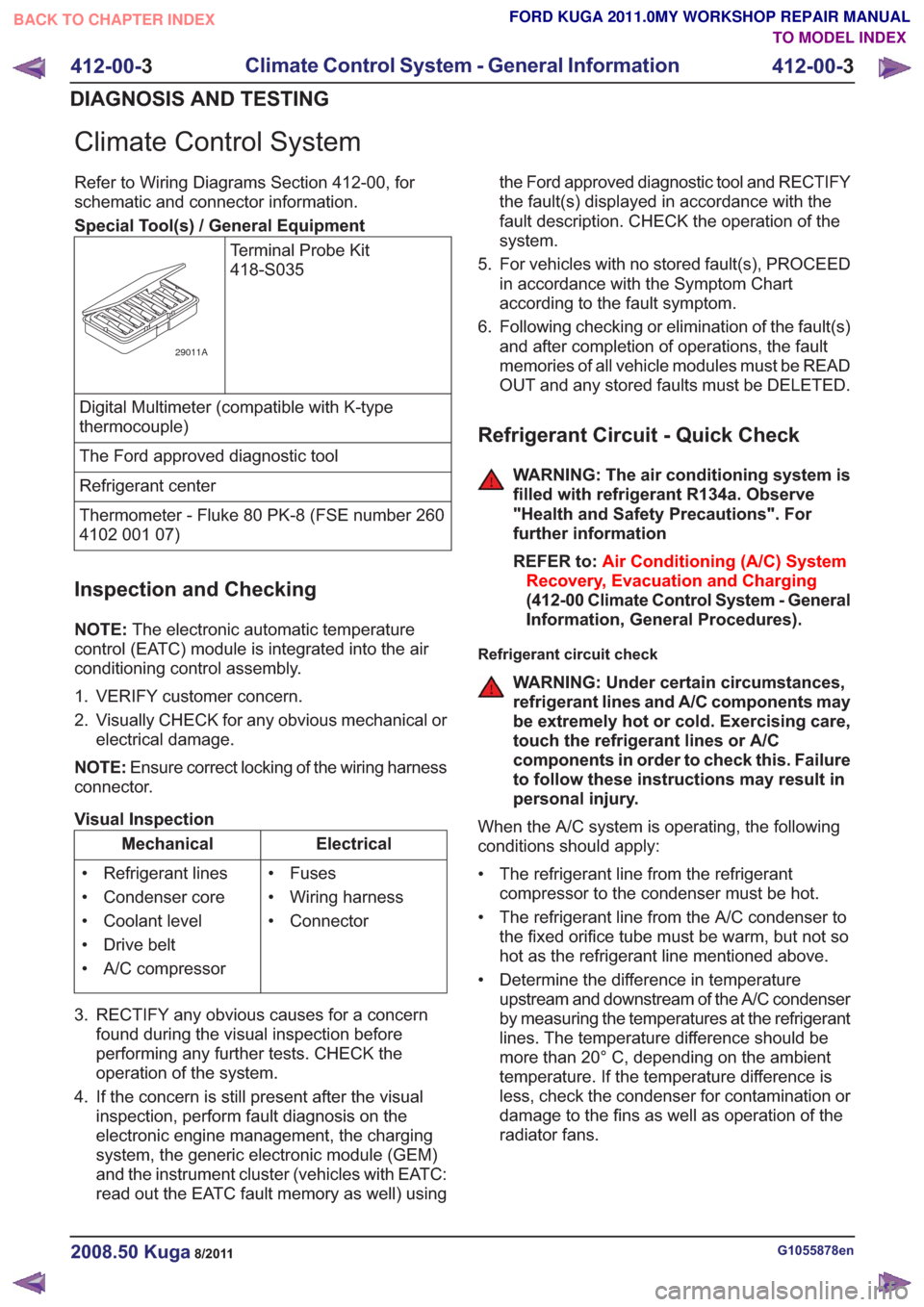
Special Tool(s) / General EquipmentTerminal Probe Kit
418-S035
29011A
Digital Multimeter (compatible with K-type
thermocouple)
The Ford approved diagnostic tool
Refrigerant center
Thermometer - Fluke 80 PK-8 (FSE number 260
4102 001 07)
Inspection and Checking
NOTE:The electronic automatic temperature
control (EATC) module is integrated into the air
conditioning control assembly.
1. VERIFY customer concern.
2. Visually CHECK for any obvious mechanical or electrical damage.
NOTE: Ensure correct locking of the wiring harness
connector.
Visual Inspection
Electrical
Mechanical
• Fuses
• Wiring harness
• Connector
• Refrigerant lines
• Condenser core
• Coolant level
• Drive belt
• A/C compressor
3. RECTIFY any obvious causes for a concern found during the visual inspection before
performing any further tests. CHECK the
operation of the system.
4. If the concern is still present after the visual inspection, perform fault diagnosis on the
electronic engine management, the charging
system, the generic electronic module (GEM)
and the instrument cluster (vehicles with EATC:
read out the EATC fault memory as well) using the Ford approved diagnostic tool and RECTIFY
the fault(s) displayed in accordance with the
fault description. CHECK the operation of the
system.
5. For vehicles with no stored fault(s), PROCEED in accordance with the Symptom Chart
according to the fault symptom.
6. Following checking or elimination of the fault(s) and after completion of operations, the fault
memories of all vehicle modules must be READ
OUT and any stored faults must be DELETED.
Refrigerant Circuit - Quick Check
WARNING: The air conditioning system is
filled with refrigerant R134a. Observe
"Health and Safety Precautions". For
further information
REFER to: Air Conditioning (A/C) System
Recovery, Evacuation and Charging
(412-00 Climate Control System - General
Information, General Procedures).
Refrigerant circuit check
WARNING: Under certain circumstances,
refrigerant lines and A/C components may
be extremely hot or cold. Exercising care,
touch the refrigerant lines or A/C
components in order to check this. Failure
to follow these instructions may result in
personal injury.
When the A/C system is operating, the following
conditions should apply:
• The refrigerant line from the refrigerant compressor to the condenser must be hot.
• The refrigerant line from the A/C condenser to the fixed orifice tube must be warm, but not so
hot as the refrigerant line mentioned above.
• Determine the difference in temperature upstream and downstream of the A/C condenser
by measuring the temperatures at the refrigerant
lines. The temperature difference should be
more than 20° C, depending on the ambient
temperature. If the temperature difference is
less, check the condenser for contamination or
damage to the fins as well as operation of the
radiator fans.
G1055878en2008.50 Kuga8/2011
412-00- 3
Climate Control System - General Information
412-00- 3
DIAGNOSIS AND TESTING
TO MODEL INDEX
BACK TO CHAPTER INDEX
FORD KUGA 2011.0MY WORKSHOP REPAIR MANUAL
Page 2055 of 2057

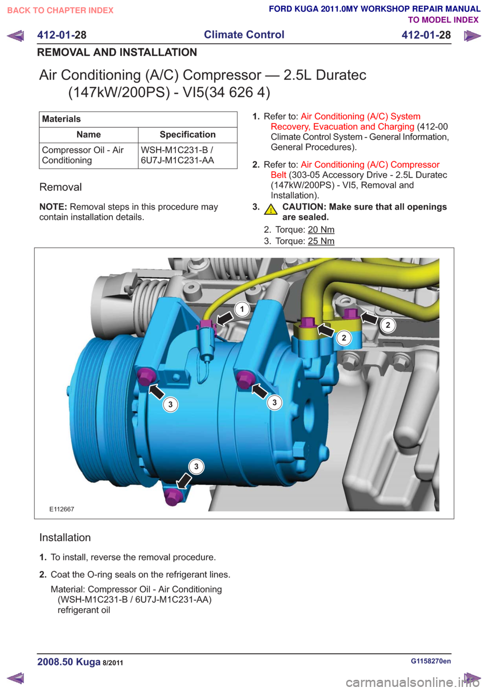
Air Conditioning (A/C) Compressor — 2.5L Duratec(147kW/200PS) - VI5(34 626 4)
Materials
Specification
Name
WSH-M1C231-B /
6U7J-M1C231-AA
Compressor Oil - Air
Conditioning
Removal
NOTE:
Removal steps in this procedure may
contain installation details. 1.
Refer to: Air Conditioning (A/C) System
Recovery, Evacuation and Charging (412-00
Climate Control System - General Information,
General Procedures).
2. Refer to: Air Conditioning (A/C) Compressor
Belt (303-05 Accessory Drive - 2.5L Duratec
(147kW/200PS) - VI5, Removal and
Installation).
3. CAUTION: Make sure that all openings are sealed.
2. Torque: 20Nm
3. Torque: 25Nm
E112667
1
2
3
2
33
Installation
1.To install, reverse the removal procedure.
2. Coat the O-ring seals on the refrigerant lines.
Material: Compressor Oil - Air Conditioning
(WSH-M1C231-B / 6U7J-M1C231-AA)
refrigerant oil
G1158270en2008.50 Kuga8/2011
412-01- 28
Climate Control
412-01- 28
REMOVAL AND INSTALLATION
TO MODEL INDEX
BACK TO CHAPTER INDEX
FORD KUGA 2011.0MY WORKSHOP REPAIR MANUAL