2011 FORD KUGA ignition switch
[x] Cancel search: ignition switchPage 462 of 2057

Output signals
SWITCH the wiper switch to the "intermittent""
position to test the output signals. PRESSING the
heated rear window switch activates the output
signals in the following order:
a.
Left-hand turn signal
b. Right-hand turn signal
c. Main beam
d. Dipped beam
e. Windshield wiper stage I
f. Windshield wiper stage II
g. Heated rear windshield
h. Heater blower motor
i. Headlamp washer system (vehicles with HID headlamps)
j. Electric booster heater (if fitted)
k. Autolamps (position lamps only if fitted)
l. Alarm horn (vehicles with alarm system)
m. Rear window wiper
n. Heated front window relay
When the heated rear window switch is pressed
again, the test of the relevant signal is terminated.
When the heated rear window switch is pressed
once more, the test for the next signal in the list is
started.
End service mode
The GEM automatically ends service mode 20
seconds after the last input or at a driving speed
of over 7km/h. However, service mode can be
manually ended at any time by proceeding as
follows:
• PRESS and HOLD the switch of the heated rear
window
• SWITCH OFF the ignition.
• RELEASE the switch of the heated rear window
3 signals sound and the turn signal lamps illuminate
to indicate that service mode has ended.
Reset service mode
If, after completion of service mode, some functions
do not operate or do not operate properly, check
the following functions:
• Instrument cluster illumination, side marker lamps (side lights) and licence plate lamp in
automatic headlamps mode
• Rear wiper
• Headlamp washer assembly
• Electric booster heater • Alarm horn
• Heated windshield
If one or more of the listed functions is not OK, it's
possible that the cause of the fault is due to not
exiting service mode properly. To reactivate the
functions correctly, perform the following steps:
1. Switch off the ignition.
2. SWITCH OFF the switch for the windscreen
wash/wipe system
3. OPERATE the switch of the heated rear window
and HOLD IT THERE
4. SWITCH ON the ignition.
5. RELEASE the heated rear window switch (an acoustic signal will sound if activation has been
performed correctly)
6. SWITCH the windscreen wash/wipe switch to the "Intermittent wipe" position
7. OPERATE the heated rear window switch 6 times (the main beam headlamps switch on and
off automatically)
8. SWITCH OFF the switch for the windscreen wash/wipe system
9. OPERATE the switch of the heated rear window
and HOLD IT THERE
10. Switch off the ignition.
11. RELEASE the heated rear window switch (three
acoustic signals will sound if activation has been
performed correctly)
After completion of the work, check all the
functions.
Inspection and Checking
NOTE: The generic electronic module (GEM) is
integrated into the central junction box (CJB).
1. VERIFY customer concern.
2. Visually CHECK for any obvious mechanical or electrical damage.
NOTE: Ensure correct locking of the wiring harness
connector.
Visual Inspection Electrical
Fuses
Wiring harness Connectors G1055084en
2008.50 Kuga 8/2011 419-10-12
Multifunction Electronic Modules
419-10-12
DIAGNOSIS AND TESTINGTO MODEL INDEX
BACK TO CHAPTER INDEX
FORD KUGA 2011.0MY WORKSHOP REPAIR MANUAL
Page 1422 of 2057
Description
Item
Front wheel sensor, right-hand side
8Description
Item
9 ESP switch
Testing the brakes on a roller dynamometer
- 4X4 vehicles only
On 4X4 vehicles a brake test on a roller
dynamometer must only be performed under the
following conditions.
• The brake test must not exceed a duration of 1 minute.
• Ignition key in position 0.
• The roller speed must not exceed 5 km/h.
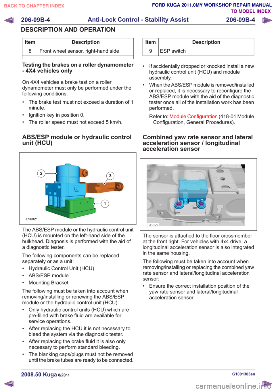
ABS/ESP module or hydraulic control
unit (HCU)
E96821
1
23
The ABS/ESP module or the hydraulic control unit
(HCU) is mounted on the left-hand side of the
bulkhead. Diagnosis is performed with the aid of
a diagnostic tester.
The following components can be replaced
separately or as a unit:
• Hydraulic Control Unit (HCU)
• ABS/ESP module
• Mounting Bracket
The following must be taken into account when
removing/installing or renewing the ABS/ESP
module or the hydraulic control unit (HCU):
• Only hydraulic control units (HCU) which are pre-filled with brake fluid are available for
service operations.
• After replacing the HCU it is not necessary to bleed the system via the diagnostic tester.
• After replacing the brake fluid it is also only necessary to perform standard bleeding.
• The blanking caps/plugs must not be removed until the brake tubes are ready to be connected. • If accidentally dropped or knocked install a new
hydraulic control unit (HCU) and module
assembly.
• When the ABS/ESP module is removed/installed or replaced, it is necessary to reconfigure the
ABS/ESP module with the aid of the diagnostic
tester once all of the installation work has been
performed.
Refer to: Module Configuration (418-01 Module
Configuration, General Procedures).
Combined yaw rate sensor and lateral
acceleration sensor / longitudinal
acceleration sensor
E96822
The sensor is attached to the floor crossmember
at the front right. For vehicles with 4x4 drive, a
longitudinal acceleration sensor is also integrated
in the same housing.
The following must be taken into account when
removing/installing or replacing the combined yaw
rate sensor and lateral/longitudinal acceleration
sensor:
• Ensure the correct installation position of the yaw rate sensor and lateral/longitudinal
acceleration sensor.
G1001303en2008.50 Kuga8/2011
206-09B- 4
Anti-Lock Control - Stability Assist
206-09B- 4
DESCRIPTION AND OPERATION
TO MODEL INDEX
BACK TO CHAPTER INDEX
FORD KUGA 2011.0MY WORKSHOP REPAIR MANUAL
Page 1431 of 2057
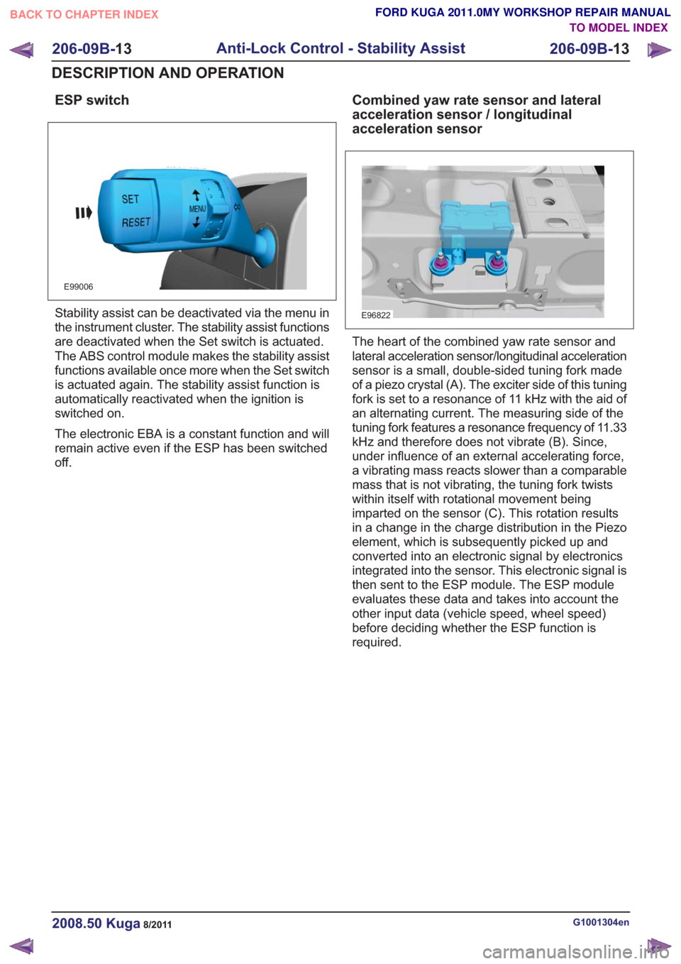
ESP switch
E99006
Stability assist can be deactivated via the menu in
the instrument cluster. The stability assist functions
are deactivated when the Set switch is actuated.
The ABS control module makes the stability assist
functions available once more when the Set switch
is actuated again. The stability assist function is
automatically reactivated when the ignition is
switched on.
The electronic EBA is a constant function and will
remain active even if the ESP has been switched
off.
Combined yaw rate sensor and lateral
acceleration sensor / longitudinal
acceleration sensor
E96822
The heart of the combined yaw rate sensor and
lateral acceleration sensor/longitudinal acceleration
sensor is a small, double-sided tuning fork made
of a piezo crystal (A). The exciter side of this tuning
fork is set to a resonance of 11 kHz with the aid of
an alternating current. The measuring side of the
tuning fork features a resonance frequency of 11.33
kHz and therefore does not vibrate (B). Since,
under influence of an external accelerating force,
a vibrating mass reacts slower than a comparable
mass that is not vibrating, the tuning fork twists
within itself with rotational movement being
imparted on the sensor (C). This rotation results
in a change in the charge distribution in the Piezo
element, which is subsequently picked up and
converted into an electronic signal by electronics
integrated into the sensor. This electronic signal is
then sent to the ESP module. The ESP module
evaluates these data and takes into account the
other input data (vehicle speed, wheel speed)
before deciding whether the ESP function is
required.
G1001304en2008.50 Kuga8/2011
206-09B-13
Anti-Lock Control - Stability Assist
206-09B- 13
DESCRIPTION AND OPERATION
TO MODEL INDEX
BACK TO CHAPTER INDEX
FORD KUGA 2011.0MY WORKSHOP REPAIR MANUAL
Page 1432 of 2057
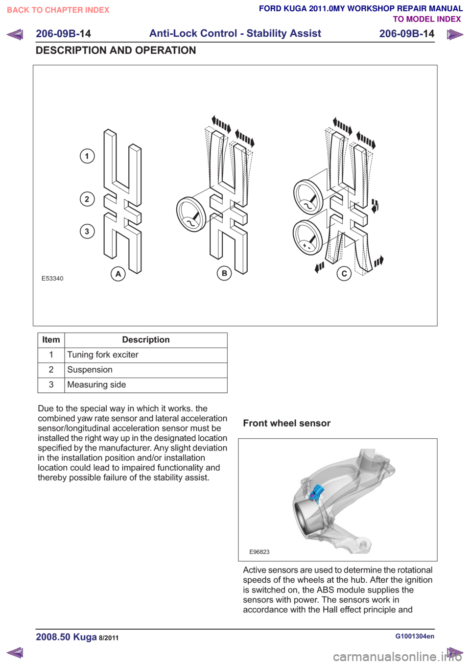
E53340
1
2
3
Description
Item
Tuning fork exciter
1
Suspension
2
Measuring side
3
Due to the special way in which it works. the
combined yaw rate sensor and lateral acceleration
sensor/longitudinal acceleration sensor must be
installed the right way up in the designated location
specified by the manufacturer. Any slight deviation
in the installation position and/or installation
location could lead to impaired functionality and
thereby possible failure of the stability assist.
Front wheel sensor
E96823
Active sensors are used to determine the rotational
speeds of the wheels at the hub. After the ignition
is switched on, the ABS module supplies the
sensors with power. The sensors work in
accordance with the Hall effect principle and
G1001304en2008.50 Kuga8/2011
206-09B- 14
Anti-Lock Control - Stability Assist
206-09B- 14
DESCRIPTION AND OPERATION
TO MODEL INDEX
BACK TO CHAPTER INDEX
FORD KUGA 2011.0MY WORKSHOP REPAIR MANUAL
Page 1447 of 2057
Steering Gear Checks After a Collision
General EquipmentFeeler gauge
Straight edge
Items to be observed when checking the steering
system
The following list of steering gear conditions and
the methods of testing should be taken into account
when carrying out checks to the steering system:
• If the steering gear has no faults after completing the following checks, do not install
a new steering gear.
• Surface corrosion and marks on the tie-rod are acceptable.
• When checking for turning effort torque peaks in the steering gear, turn the steering wheel from
steering lock stop to steering lock stop in
approximately 15 seconds.
• A steady increase of turning effort torque from steering center to steering lock stop is
acceptable.
• When checking for power steering fluid leaks, turn the steering wheel to the steering lock stop
in approximately 10 seconds.
• Noises from the power steering, for example the power steering pump relief valve, are
acceptable.
STEERING GEAR HOUSING
1. Raise and support the vehicle. REFER to: Lifting(100-02 Jacking and Lifting,
Description and Operation).
2. Visually inspect the steering gear housing for cracks and damage. If the steering gear housing
is cracked or damaged, install a new steering
gear.
REFER to: Steering Gear (211-02 Power
Steering, Removal and Installation).
TIE-RODS
1. Using a straight edge and feeler gauge, check the tie-rods to see if they are straight. If the
distance between the tie-rod and straight edge is greater than 0.5 mm, install a new steering
gear.
REFER to:
Steering Gear (211-02 Power
Steering, Removal and Installation).
2. Check the tightening torque of the tie-rod end to wheel knuckle nut.
REFER to: Tie Rod End (211-03 Steering
Linkage, Removal and Installation).
3. Check the tightening torque of the tie-rod end locking nut.
REFER to: Tie Rod End (211-03 Steering
Linkage, Removal and Installation).
CHECK FOR TURNING EFFORT TORQUE
PEAKS IN THE STEERING GEAR
1. Lower and support the vehicle making sure that the road wheels are just clear of the floor.
2. With the ignition switch in position I, slowly turn the steering wheel from steering lock stop to
steering lock stop. If a turning effort torque peak
or judder is felt while turning the steering wheel,
detach the tie-rods from the wheel knuckles.
3. Slowly turn the steering wheel from steering lock stop to steering lock stop. If a turning effort
torque peak or judder is felt while turning the
steering wheel, install a new steering gear.
REFER to: Steering Gear (211-02 Power
Steering, Removal and Installation).
CHECK FOR POWER STEERING FLUID LEAKS
1. Lower the vehicle.
2. Run the engine at a fast idle and slowly turn the steering wheel to the left-hand steering lock
stop. Hold the steering wheel in this position for
5 seconds with a turning effort torque of 15 Nm
at the steering wheel rim.
3. Turn the steering wheel away from the left-hand steering lock stop for 30 seconds.
4. Run the engine at a fast idle and slowly turn the steering wheel to the right-hand steering lock
stop. Hold the steering wheel in this position for
5 seconds with a turning effort torque of 15 Nm
at the steering wheel rim.
5. Turn the steering wheel away from the right-hand steering lock stop.
6. Check for power steering fluid leaks at the steering gear housing and the power steering
line connections to the steering gear. If there is
G538091en2008.50 Kuga8/2011
211-00- 6
Steering System - General Information
211-00- 6
DIAGNOSIS AND TESTING
TO MODEL INDEX
BACK TO CHAPTER INDEX
FORD KUGA 2011.0MY WORKSHOP REPAIR MANUAL
Page 1465 of 2057
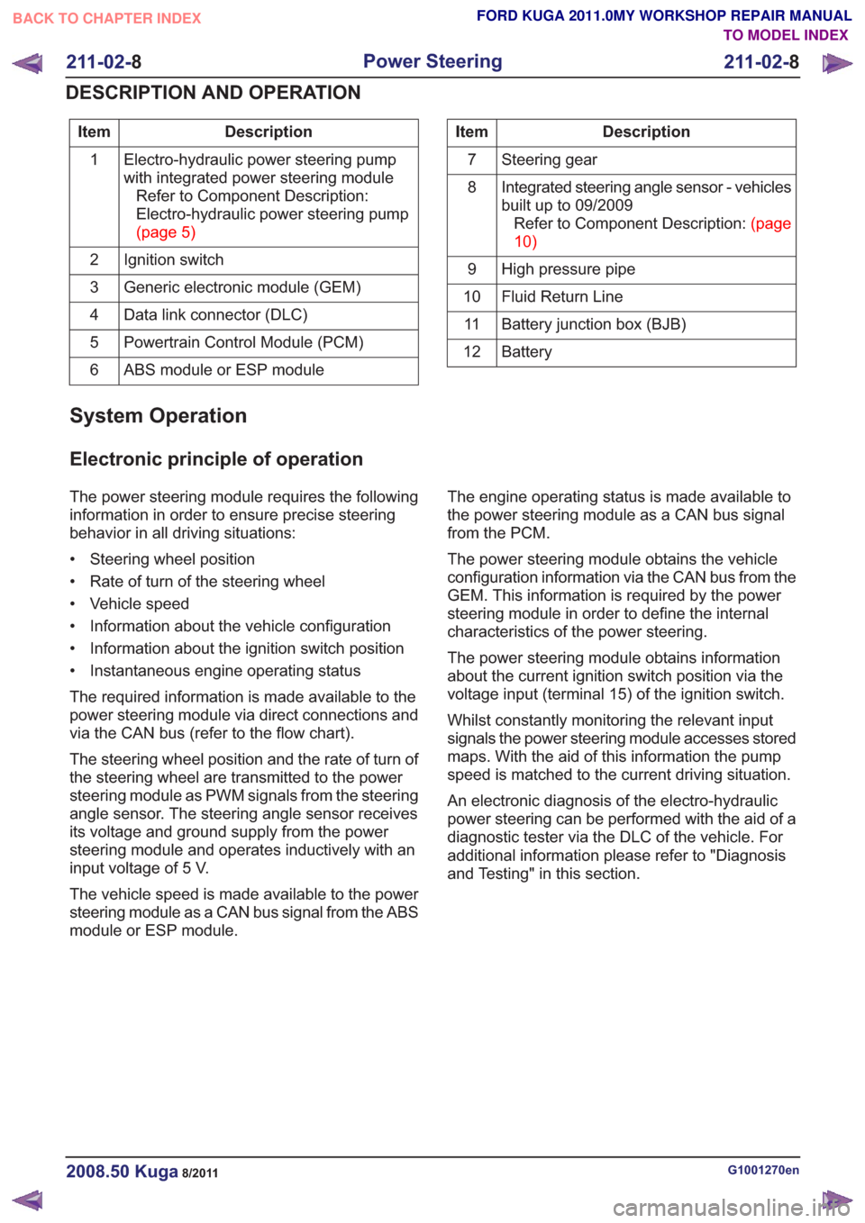
Description
Item
Electro-hydraulic power steering pump
with integrated power steering moduleRefer to Component Description:
Electro-hydraulic power steering pump
(page5)
1
Ignition switch
2
Generic electronic module (GEM)
3
Data link connector (DLC)
4
Powertrain Control Module (PCM)
5
ABS module or ESP module
6Description
Item
Steering gear
7
Integrated steering angle sensor - vehicles
built up to 09/2009RefertoComponentDescription:(page
10)
8
High pressure pipe
9
Fluid Return Line
10
Battery junction box (BJB)
11
Battery
12
System Operation
Electronic principle of operation
The power steering module requires the following
information in order to ensure precise steering
behavior in all driving situations:
• Steering wheel position
• Rate of turn of the steering wheel
• Vehicle speed
• Information about the vehicle configuration
• Information about the ignition switch position
• Instantaneous engine operating status
The required information is made available to the
power steering module via direct connections and
via the CAN bus (refer to the flow chart).
The steering wheel position and the rate of turn of
the steering wheel are transmitted to the power
steering module as PWM signals from the steering
angle sensor. The steering angle sensor receives
its voltage and ground supply from the power
steering module and operates inductively with an
input voltage of 5 V.
The vehicle speed is made available to the power
steering module as a CAN bus signal from the ABS
module or ESP module. The engine operating status is made available to
the power steering module as a CAN bus signal
from the PCM.
The power steering module obtains the vehicle
configuration information via the CAN bus from the
GEM. This information is required by the power
steering module in order to define the internal
characteristics of the power steering.
The power steering module obtains information
about the current ignition switch position via the
voltage input (terminal 15) of the ignition switch.
Whilst constantly monitoring the relevant input
signals the power steering module accesses stored
maps. With the aid of this information the pump
speed is matched to the current driving situation.
An electronic diagnosis of the electro-hydraulic
power steering can be performed with the aid of a
diagnostic tester via the DLC of the vehicle. For
additional information please refer to "Diagnosis
and Testing" in this section.
G1001270en2008.50 Kuga8/2011
211-02-
8
Power Steering
211-02- 8
DESCRIPTION AND OPERATION
TO MODEL INDEX
BACK TO CHAPTER INDEX
FORD KUGA 2011.0MY WORKSHOP REPAIR MANUAL
Page 1695 of 2057
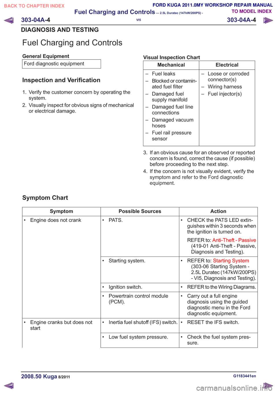
Fuel Charging and Controls
General EquipmentFord diagnostic equipment
Inspection and Verification
1. Verify the customer concern by operating the system.
2. Visually inspect for obvious signs of mechanical or electrical damage. Visual Inspection Chart
Electrical
Mechanical
– Loose or corrodedconnector(s)
– Wiring harness
– Fuel injector(s)
– Fuel leaks
– Blocked or contamin-
ated fuel filter
– Damaged fuel supply manifold
– Damaged fuel line connections
– Damaged vacuum hoses
– Fuel rail pressure sensor
3. If an obvious cause for an observed or reported concern is found, correct the cause (if possible)
before proceeding to the next step.
4. If the concern is not visually evident, verify the symptom and refer to the Ford diagnostic
equipment .
Symptom Chart
Action
Possible Sources
Symptom
• CHECK the PATS LED extin-guishes within 3 seconds when
the ignition is turned on.
REFER to: Anti-Theft - Passive
(419-01 Anti-Theft - Passive,
Diagnosis and Testing).
• PAT S .
• Engine does not crank
• REFER to:Starting System
(303-06 Starting System -
2.5L Duratec (147kW/200PS)
- VI5, Diagnosis and Testing).
• Starting system.
• REFER to the Wiring Diagrams.
• Ignition switch.
• Carry out a full enginediagnosis using the guided
diagnostic menu in the Ford
diagnostic equipment.
• Powertrain control module
(PCM).
• RESET the IFS switch.
• Inertia fuel shutoff (IFS) switch.
• Engine cranks but does not
start
• Check the fuel system pres-sure.
• Low fuel system pressure.
G1183441en2008.50 Kuga8/2011
303-04A-
4
Fuel Charging and Controls
— 2.5L Duratec (147kW/200PS) -
VI5
303-04A- 4
DIAGNOSIS AND TESTING
TO MODEL INDEX
BACK TO CHAPTER INDEX
FORD KUGA 2011.0MY WORKSHOP REPAIR MANUAL
Page 1748 of 2057
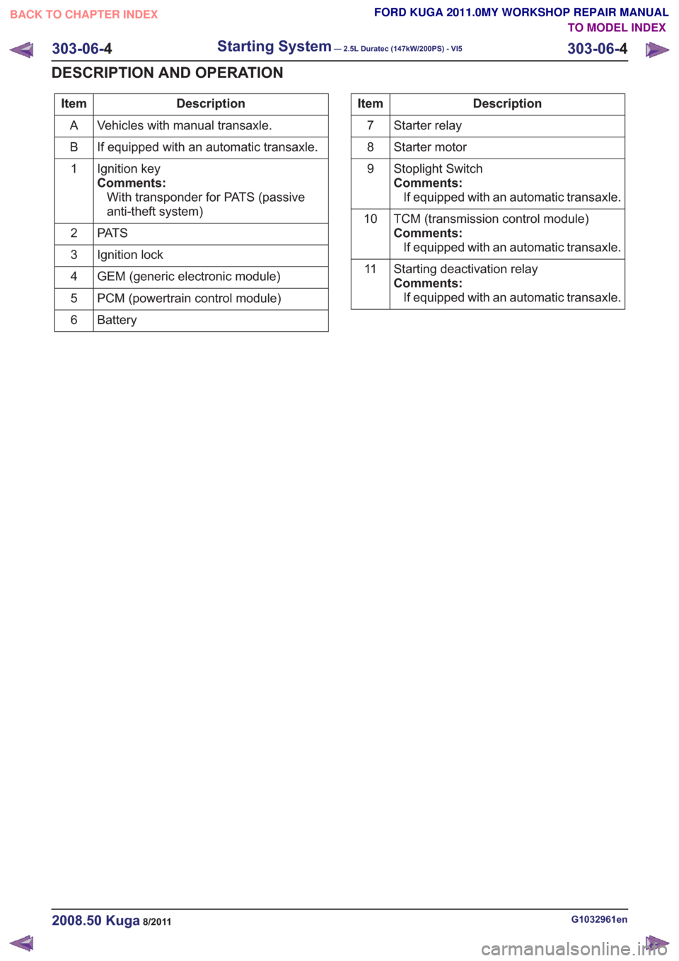
Description
Item
Vehicles with manual transaxle.
A
If equipped with an automatic transaxle.
B
Ignition key
Comments:With transponder for PATS (passive
anti-theft system)
1
PAT S
2
Ignition lock
3
GEM (generic electronic module)
4
PCM (powertrain control module)
5
Battery
6Description
Item
Starter relay
7
Starter motor
8
Stoplight Switch
Comments:If equipped with an automatic transaxle.
9
TCM (transmission control module)
Comments:If equipped with an automatic transaxle.
10
Starting deactivation relay
Comments:If equipped with an automatic transaxle.
11
G1032961en2008.50 Kuga8/2011
303-06-
4
Starting System— 2.5L Duratec (147kW/200PS) - VI5303-06-
4
DESCRIPTION AND OPERATION
TO MODEL INDEX
BACK TO CHAPTER INDEX
FORD KUGA 2011.0MY WORKSHOP REPAIR MANUAL