2011 FORD KUGA climate control
[x] Cancel search: climate controlPage 451 of 2057

SECTION 419-10 Multifunction Electronic Modules
VEHICLE APPLICATION:
2008.50 Kuga
PAGE
CONTENTS
DESCRIPTION AND OPERATION
419-10-2
Module Controlled Functions (Overview)...........................................................................
419-10-2
Generic electronics module (GEM)....................................................................................
419-10-2
Emergency function............................................................................................................
419-10-2
Service mode......................................................................................................................
419-10-4
Module Controlled Functions (System Operation and Component Description)................
419-10-4
System Diagram.................................................................................................................
419-10-6
System Operation...............................................................................................................
419-10-6
GEM. ...............................................................................................................................
419-10-6
Component Description......................................................................................................
419-10-6
Battery charging (Smart Charge)....................................................................................
419-10-7
Ignition overload protection.............................................................................................
419-10-7
Headlamp switch-off delay..............................................................................................
419-10-8
Turn signals....................................................................................................................
419-10-8
Interior lighting................................................................................................................
419-10-8
Heated windscreen.........................................................................................................
419-10-9
Heated rear window and heated external mirrors...........................................................
419-10-9
Ambient air temperature.................................................................................................
419-10-9
Brake fluid level...............................................................................................................
419-10-9
Automatic headlamps.....................................................................................................
419-10-9
Combined rain sensor/light sensor.................................................................................419-10-10Windshield wash/wipe system........................................................................................
419-10-10Anti-theft ..........................................................................................................................
419-10-10Electric booster Heater...................................................................................................
419-10-10Climate control................................................................................................................
DIAGNOSIS AND TESTING 419-10-11
Generic Electronic Module (GEM)......................................................................................
419-10-11
Description of operation......................................................................................................
419-10-12
Inspection and Checking....................................................................................................
REMOVAL AND INSTALLATION 419-10-14
Generic Electronic Module (GEM)......................................................................................
419-10-15
Lighting Control Module (LCM)........................................................................................... 419-10-1
Multifunction Electronic Modules
419-10-1
.
TO MODEL INDEX
BACK TO CHAPTER INDEX
FORD KUGA 2011.0MY WORKSHOP REPAIR MANUAL
Page 456 of 2057

Description
Item
HS CAN
1
DLC2
MS CAN
3
Instrument cluster (gateway)
4
Front windshield wiper motors
5
GEM6
Rear window wiper motors
7
Indicator/heated windshield
8
Indicator/heated rear window
9 Description
Item
Mini-liftgate latch motor
10
Liftgate latch motor
11
Electric booster Heater
12
Front wiper windscreen washer pump
13
Rear wiper windscreen washer pump
14
Headlamp
15
Courtesy Lighting
16
Alarm horn
17
System Operation
GEM.
The following functions are controlled or performed
by the GEM at a battery voltage of between 9 and
16 volts:
• Current distribution
• Battery charging (Smart Charge)
• Ignition overload protection
• Headlamp switch-off delay
• Turn signals
• Interior lighting
• Heated windscreen
• Heated rear window and heated external mirrors
• Ambient air temperature
• Brake fluid level
• Automatic headlamps
• Combined rain sensor/light sensor
• Windshield wash/wipe system
• Speed control – reads the speed control switches andtransmits signals on the CAN data bus
• central door locking – transmits signals on the CAN data bus
• Anti-theft
• Electric booster Heater
• Climate control
• Parking brake –(monitors the switch and transmits the signal
on the CAN data bus
• Communication via the medium-speed CAN data bus Component Description
Battery charging (Smart Charge)
In addition to the familiar functions, the Smart
Charge system also performs the following
functions:
•
Automatic deactivation of non-critical high power
electrical consumers when the battery voltage
is low in order to reduce the level of current
drawn.
• Automatic activation of non-critical high power electrical consumers when the battery voltage
is excessively high in order to protect
components which are sensitive to increased
voltages.
The battery charging current is optimized through
continuous calculation of the battery temperature
and monitoring of the alternator output voltage.
The alternator load is signaled to the PCM
(powertrain control module) in order to provide it
with an early indication when an electric component
is to be switched on or off, thereby also providing
information about imminent changes to the amount
of torque demanded by the alternator. By
evaluating this information the PCM is capable of
increasing the stability of the engine under idling.
The two remaining functions of the Smart Charge
system are controlled by the GEM. G1030788en
2008.50 Kuga 8/2011 419-10-6
Multifunction Electronic Modules
419-10-6
DESCRIPTION AND OPERATIONTO MODEL INDEX
BACK TO CHAPTER INDEX
FORD KUGA 2011.0MY WORKSHOP REPAIR MANUAL
Page 460 of 2057

Windshield wash/wipe system
Refer to:
Wipers and Washers (501-16 Wipers and
Washers, Description and Operation).
Anti-theft
Refer to: Anti-Theft - Active (419-01 Anti-Theft -
Active, Description and Operation).
Electric booster Heater
Refer to: Auxiliary Climate Control (412-02 Auxiliary
Climate Control, Description and Operation).
Climate control
Refer to: Climate Control (412-01 Climate Control,
Description and Operation). G1030788en
2008.50 Kuga 8/2011 419-10-10
Multifunction Electronic Modules
419-10-10
DESCRIPTION AND OPERATIONTO MODEL INDEX
BACK TO CHAPTER INDEX
FORD KUGA 2011.0MY WORKSHOP REPAIR MANUAL
Page 1406 of 2057

Brake Booster — 2.5L Duratec (147kW/200PS) - VI5, RHD4WD/RHD FWD(12 451 0)
Removal
NOTE: Removal steps in this procedure may
contain installation details.
1. Refer to: Brake System Health and Safety
Precautions (100-00 General Information,
Description and Operation).
2. Torque: 24
Nm
E69829
x4
1
2
3.Refer to: Air Conditioning (A/C) System
Recovery, Evacuation and Charging (412-00
Climate Control System - General Information,
General Procedures).
Refer to: Brake Master Cylinder - 2.5L Duratec
(147kW/200PS) - VI5 (206-06 Hydraulic Brake
Actuation, Removal and Installation).
Refer to: Lifting(100-02 Jacking and Lifting,
Description and Operation).
4.
E65299
5. Torque:
• Stage 1: 10
Nm
• Stage 2: 25Nm
E99866
x6
6.
G1185955en2008.50 Kuga8/2011
206-07- 2
Power Brake Actuation
206-07- 2
REMOVAL AND INSTALLATION
TO MODEL INDEX
BACK TO CHAPTER INDEX
FORD KUGA 2011.0MY WORKSHOP REPAIR MANUAL
Page 1790 of 2057

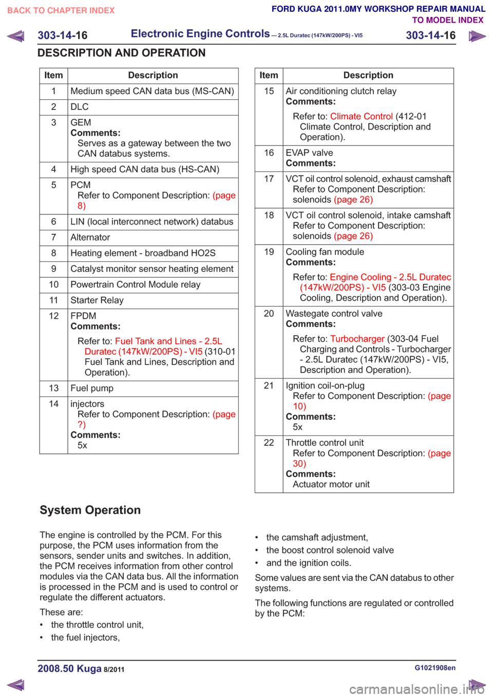
Description
Item
Medium speed CAN data bus (MS-CAN)
1
DLC
2
GEM
Comments:Serves as a gateway between the two
CAN databus systems.
3
High speed CAN data bus (HS-CAN)
4
PCMRefertoComponentDescription:(page
8)
5
LIN (local interconnect network) databus
6
Alternator
7
Heating element - broadband HO2S
8
Catalyst monitor sensor heating element
9
Powertrain Control Module relay
10
Starter Relay
11
FPDM
Comments:Refer to: Fuel Tank and Lines - 2.5L
Duratec (147kW/200PS) - VI5 (310-01
Fuel Tank and Lines, Description and
Operation).
12
Fuel pump
13
injectorsRefertoComponentDescription:(page
?)
Comments: 5x
14Description
Item
Air conditioning clutch relay
Comments:Refer to: Climate Control (412-01
Climate Control, Description and
Operation).
15
EVAP valve
Comments:
16
VCT oil control solenoid, exhaust camshaftRefer to Component Description:
solenoids(page26)
17
VCT oil control solenoid, intake camshaftRefer to Component Description:
solenoids(page26)
18
Cooling fan module
Comments:Refer to: Engine Cooling - 2.5L Duratec
(147kW/200PS) - VI5 (303-03 Engine
Cooling, Description and Operation).
19
Wastegate control valve
Comments:Refer to: Turbocharger (303-04 Fuel
Charging and Controls - Turbocharger
- 2.5L Duratec (147kW/200PS) - VI5,
Description and Operation).
20
Ignition coil-on-plugRefertoComponentDescription:(page
10)
Comments: 5x
21
Throttle control unitRefertoComponentDescription:(page
30)
Comments: Actuator motor unit
22
System Operation
The engine is controlled by the PCM. For this
purpose, the PCM uses information from the
sensors, sender units and switches. In addition,
the PCM receives information from other control
modules via the CAN data bus. All the information
is processed in the PCM and is used to control or
regulate the different actuators.
These are:
• the throttle control unit,
• the fuel injectors, • the camshaft adjustment,
• the boost control solenoid valve
• and the ignition coils.
Some values are sent via the CAN databus to other
systems.
The following functions are regulated or controlled
by the PCM:
G1021908en2008.50 Kuga8/2011
303-14-
16
Electronic Engine Controls— 2.5L Duratec (147kW/200PS) - VI5303-14-
16
DESCRIPTION AND OPERATION
TO MODEL INDEX
BACK TO CHAPTER INDEX
FORD KUGA 2011.0MY WORKSHOP REPAIR MANUAL
Page 2012 of 2057

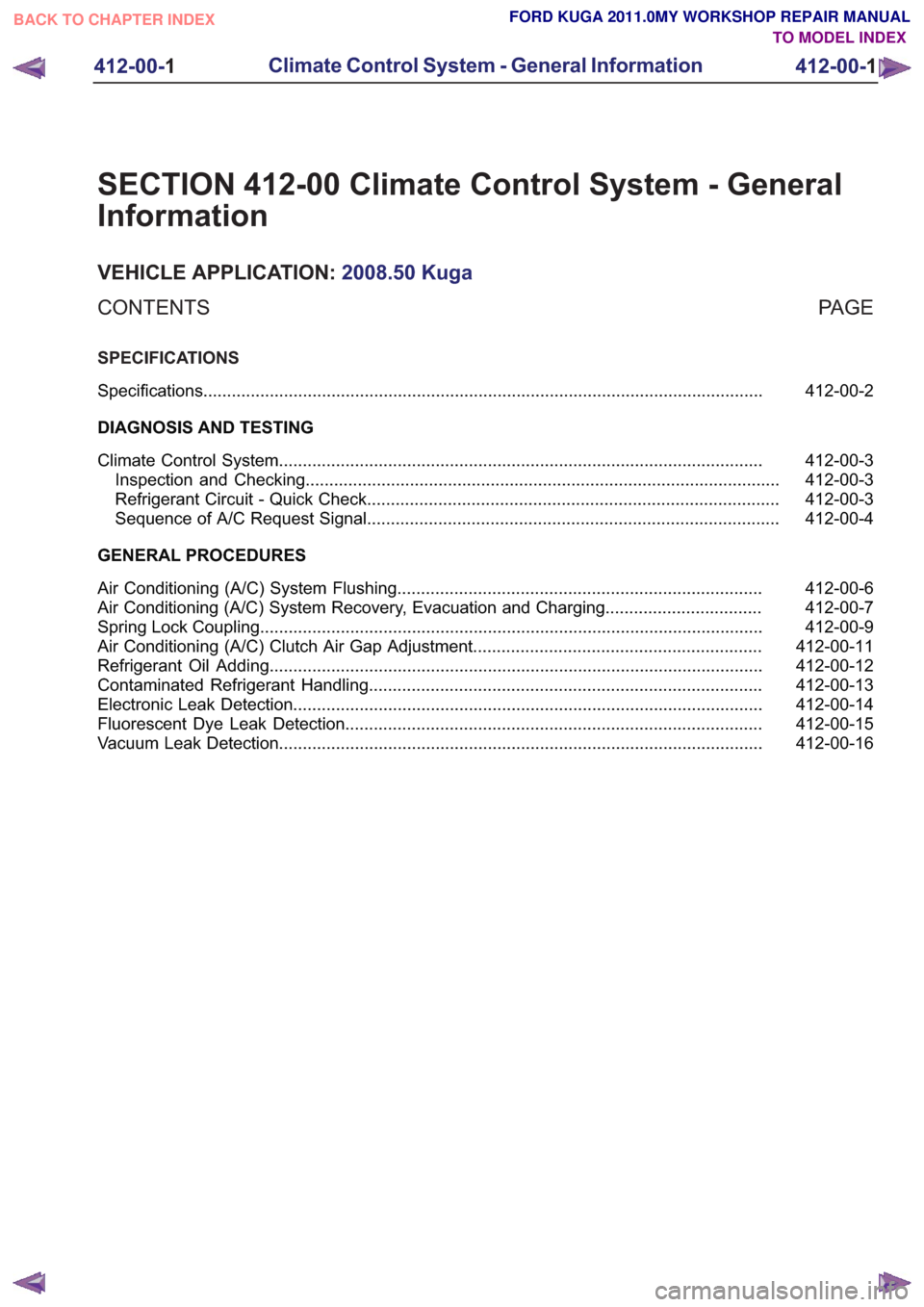
SECTION 412-00 Climate Control System - General
Information
VEHICLE APPLICATION:2008.50 Kuga
PA G E
CONTENTS
SPECIFICATIONS
412-00-2
Specifications ........................................................................\
..............................................
DIAGNOSIS AND TESTING 412-00-3
Climate Control System ........................................................................\
..............................
412-00-3
Inspection and Checking ........................................................................\
............................
412-00-3
Refrigerant Circuit - Quick Check ........................................................................\
...............
412-00-4
Sequence of A/C Request Signal ........................................................................\
...............
GENERAL PROCEDURES 412-00-6
Air Conditioning (A/C) System Flushing ........................................................................\
.....
412-00-7
Air Conditioning (A/C) System Recovery, Evacuation and Charging .................................
412-00-9
Spring Lock Coupling ........................................................................\
..................................
412-00-11
Air Conditioning (A/C) Clutch Air Gap Adjustment .............................................................
412-00-12
Refrigerant Oil Adding ........................................................................\
................................
412-00-13
Contaminated Refrigerant Handling ........................................................................\
...........
412-00-14
Electronic Leak Detection ........................................................................\
...........................
412-00-15
Fluorescent Dye Leak Detection ........................................................................\
................
412-00-16
Vacuum Leak Detection ........................................................................\
..............................
412-00-1
Climate Control System - General Information
412-00- 1
.
TO MODEL INDEX
BACK TO CHAPTER INDEX
FORD KUGA 2011.0MY WORKSHOP REPAIR MANUAL
Page 2013 of 2057

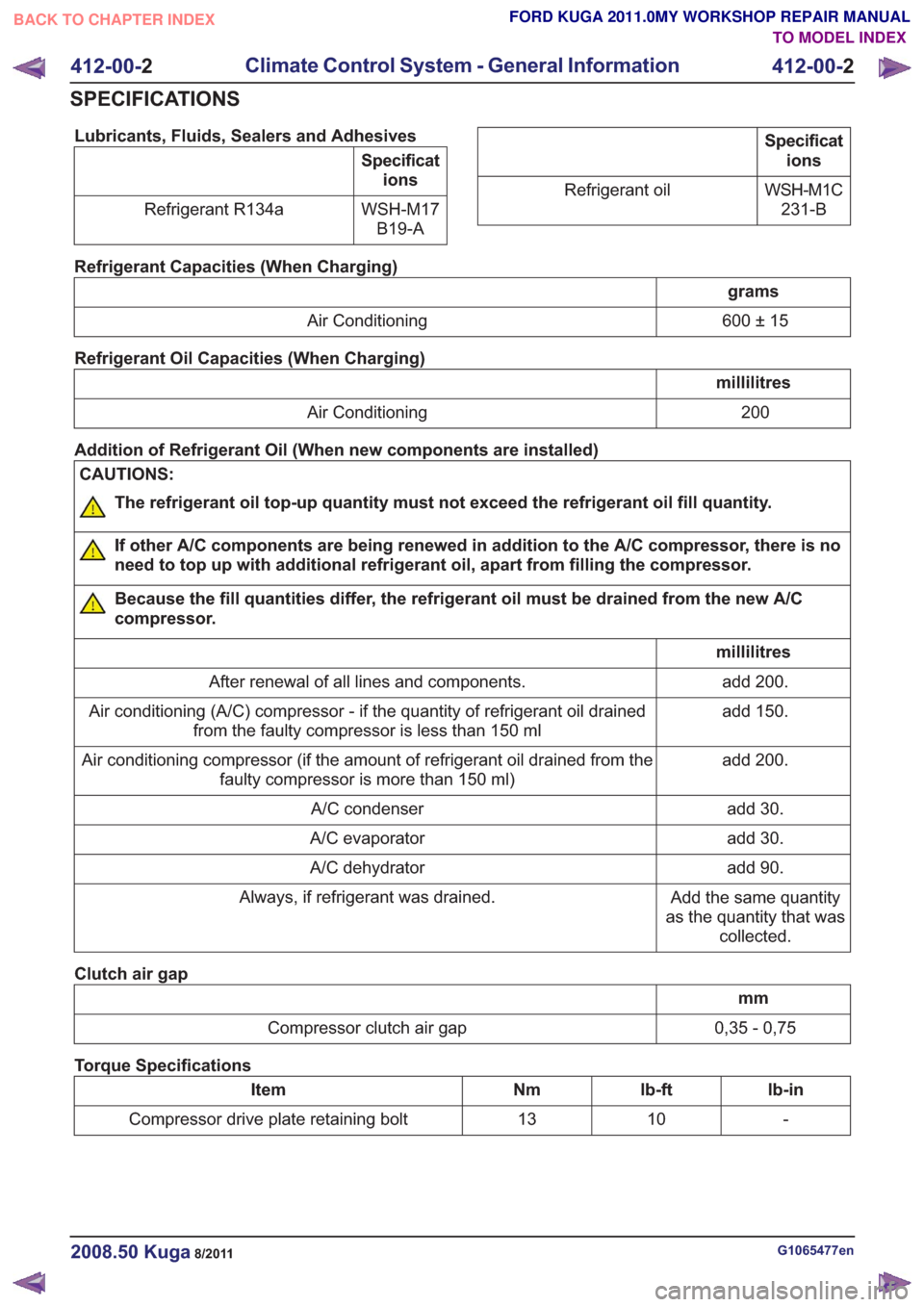
Lubricants, Fluids, Sealers and Adhesives
Specifications
WSH-M17 B19-A
Refrigerant R134a
Specificat
ions
WSH-M1C 231-B
Refrigerant oil
Refrigerant Capacities (When Charging)
grams
600 ± 15
Air Conditioning
Refrigerant Oil Capacities (When Charging)
millilitres 200
Air Conditioning
Addition of Refrigerant Oil (When new components are installed)
CAUTIONS:
The refrigerant oil top-up quantity must not exceed the refrigerant oil fill quantity.
If other A/C components are being renewed in addition to the A/C compressor, there is no
need to top up with additional refrigerant oil, apart from filling the compressor.
Because the fill quantities differ, the refrigerant oil must be drained from the new A/C
compressor.
millilitres add 200.
After renewal of all lines and components.
add 150.
Air conditioning (A/C) compressor - if the quantity of refrigerant oil drained
from the faulty compressor is less than 150 ml
add 200.
Air conditioning compressor (if the amount of refrigerant oil drained from the
faulty compressor is more than 150 ml)
add 30.
A/C condenser
add 30.
A/C evaporator
add 90.
A/C dehydrator
Add the same quantity
as the quantity that was collected.
Always, if refrigerant was drained.
Clutch air gap
mm
0,35 - 0,75
Compressor clutch air gap
Torque Specifications
lb-in
lb-ft
Nm
Item
-
10
13
Compressor drive plate retaining bolt
G1065477en2008.50 Kuga8/2011
412-00- 2
Climate Control System - General Information
412-00- 2
SPECIFICATIONS
TO MODEL INDEX
BACK TO CHAPTER INDEX
FORD KUGA 2011.0MY WORKSHOP REPAIR MANUAL
Page 2014 of 2057

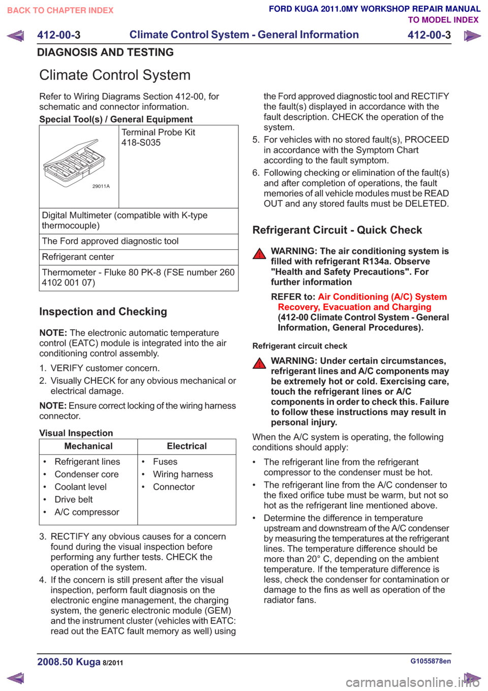
Climate Control System
Refer to Wiring Diagrams Section 412-00, for
schematic and connector information.
Special Tool(s) / General EquipmentTerminal Probe Kit
418-S035
29011A
Digital Multimeter (compatible with K-type
thermocouple)
The Ford approved diagnostic tool
Refrigerant center
Thermometer - Fluke 80 PK-8 (FSE number 260
4102 001 07)
Inspection and Checking
NOTE:The electronic automatic temperature
control (EATC) module is integrated into the air
conditioning control assembly.
1. VERIFY customer concern.
2. Visually CHECK for any obvious mechanical or electrical damage.
NOTE: Ensure correct locking of the wiring harness
connector.
Visual Inspection
Electrical
Mechanical
• Fuses
• Wiring harness
• Connector
• Refrigerant lines
• Condenser core
• Coolant level
• Drive belt
• A/C compressor
3. RECTIFY any obvious causes for a concern found during the visual inspection before
performing any further tests. CHECK the
operation of the system.
4. If the concern is still present after the visual inspection, perform fault diagnosis on the
electronic engine management, the charging
system, the generic electronic module (GEM)
and the instrument cluster (vehicles with EATC:
read out the EATC fault memory as well) using the Ford approved diagnostic tool and RECTIFY
the fault(s) displayed in accordance with the
fault description. CHECK the operation of the
system.
5. For vehicles with no stored fault(s), PROCEED in accordance with the Symptom Chart
according to the fault symptom.
6. Following checking or elimination of the fault(s) and after completion of operations, the fault
memories of all vehicle modules must be READ
OUT and any stored faults must be DELETED.
Refrigerant Circuit - Quick Check
WARNING: The air conditioning system is
filled with refrigerant R134a. Observe
"Health and Safety Precautions". For
further information
REFER to: Air Conditioning (A/C) System
Recovery, Evacuation and Charging
(412-00 Climate Control System - General
Information, General Procedures).
Refrigerant circuit check
WARNING: Under certain circumstances,
refrigerant lines and A/C components may
be extremely hot or cold. Exercising care,
touch the refrigerant lines or A/C
components in order to check this. Failure
to follow these instructions may result in
personal injury.
When the A/C system is operating, the following
conditions should apply:
• The refrigerant line from the refrigerant compressor to the condenser must be hot.
• The refrigerant line from the A/C condenser to the fixed orifice tube must be warm, but not so
hot as the refrigerant line mentioned above.
• Determine the difference in temperature upstream and downstream of the A/C condenser
by measuring the temperatures at the refrigerant
lines. The temperature difference should be
more than 20° C, depending on the ambient
temperature. If the temperature difference is
less, check the condenser for contamination or
damage to the fins as well as operation of the
radiator fans.
G1055878en2008.50 Kuga8/2011
412-00- 3
Climate Control System - General Information
412-00- 3
DIAGNOSIS AND TESTING
TO MODEL INDEX
BACK TO CHAPTER INDEX
FORD KUGA 2011.0MY WORKSHOP REPAIR MANUAL