2011 FORD KUGA Battery
[x] Cancel search: BatteryPage 1428 of 2057
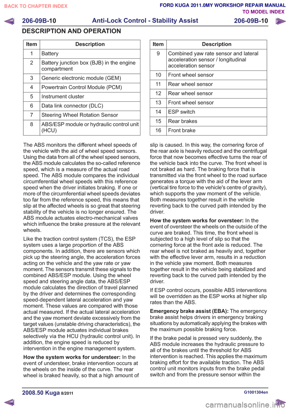
Description
Item
Battery
1
Battery junction box (BJB) in the engine
compartment
2
Generic electronic module (GEM)
3
Powertrain Control Module (PCM)
4
Instrument cluster
5
Data link connector (DLC)
6
Steering Wheel Rotation Sensor
7
ABS/ESP module or hydraulic control unit
(HCU)
8Description
Item
Combined yaw rate sensor and lateral
acceleration sensor / longitudinal
acceleration sensor
9
Front wheel sensor
10
Rear wheel sensor
11
Rear wheel sensor
12
Front wheel sensor
13
ESP switch
14
Rear brakes
15
Front brake
16
The ABS monitors the different wheel speeds of
the vehicle with the aid of wheel speed sensors.
Using the data from all of the wheel speed sensors,
the ABS module calculates the so-called reference
speed, which is a measure of the actual road
speed. The ABS module compares the individual
circumferential wheel speeds with this reference
speed when the driver initiates braking. If one or
more of the circumferential wheel speeds deviates
too far from the reference speed, this means that
slip at the affected wheels is so great that steering
stability of the vehicle is no longer ensured. The
ABS module actuates electro-mechanical valves
which influence the brake pressure at the relevant
wheels.
Like the traction control system (TCS), the ESP
system uses a large proportion of the ABS
components. In addition, there are sensors which
pick up the steering angle, the acceleration forces
acting on the vehicle and the yaw rate or yaw
moment. The sensors transmit these signals to the
combined ABS/ESP module. Using the wheel
speed and steering angle data, the ABS/ESP
module calculates the direction of travel planned
by the driver and determines the corresponding
speed-dependent lateral acceleration and yaw
moment. These values are compared with those
actual measured. If the actual lateral acceleration
and the yaw moment deviate excessively from the
target values (unstable driving characteristics), the
ABS/ESP module actuates individual brakes
selectively via the HCU (hydraulic control unit). In
addition, the engine speed is reduced by
intervention in the engine management system.
How the system works for understeer: In the
event of understeer, brake intervention occurs at
the wheels on the inside of the curve. The rear
wheel is braked heavily, so that a high amount of slip is caused. In this way, the cornering force of
the rear axle is heavily reduced and the centrifugal
force that now becomes effective turns the rear of
the vehicle back into the curve. The front wheel is
not braked as hard. The braking force that is
transmitted via the front wheel to the road surface
generates a torque with the aid of the lever arm
(vertical tire force to the vehicle's centre of gravity),
which supports the yaw moment of the vehicle.
Both measures together result in the vehicle
reverting back to the curved path intended by the
driver.
How the system works for oversteer:
In the
event of oversteer the wheels on the outside of the
curve are braked. This time, the front wheel is
subjected to a high level of slip so that the
cornering force at the front axle is reduced. The
rear wheel is not braked as heavily and, together
with the effective lever arm, results in a reduction
in the vehicle yaw moment. Both measures
together result in the vehicle being stabilized and
reverting back to the curved path intended by the
driver.
If ESP control occurs, possible ABS interventions
will be overridden as the ESP works at higher slip
rates than the ABS.
Emergency brake assist (EBA): The emergency
brake assist helps drivers in emergency braking
situations by automatically applying the brakes with
the maximum possible braking force.
If the brake pedal is pressed very suddenly, the
ABS module increases the hydraulic pressure to
all of the brakes until the threshold for ABS
intervention is reached. This applies the maximum
braking effort for the available traction. The ABS
control unit monitors inputs from the brake pedal
switch and from the pressure sensor within the
G1001304en2008.50 Kuga8/2011
206-09B- 10
Anti-Lock Control - Stability Assist
206-09B- 10
DESCRIPTION AND OPERATION
TO MODEL INDEX
BACK TO CHAPTER INDEX
FORD KUGA 2011.0MY WORKSHOP REPAIR MANUAL
Page 1434 of 2057
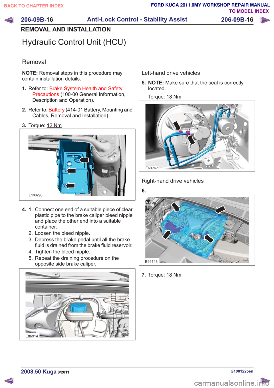
Hydraulic Control Unit (HCU)
Removal
NOTE:Removal steps in this procedure may
contain installation details.
1. Refer to: Brake System Health and Safety
Precautions (100-00 General Information,
Description and Operation).
2. Refer to: Battery(414-01 Battery, Mounting and
Cables, Removal and Installation).
3. Torque: 12
Nm
E100290
4. Connect one end of a suitable piece of clear
plastic pipe to the brake caliper bleed nipple
1.
and place the other end into a suitable
container.
2. Loosen the bleed nipple.
3. Depress the brake pedal until all the brake fluid is drained from the brake fluid reservoir.
4. Tighten the bleed nipple.
5. Repeat the draining procedure on the opposite side brake caliper.
E86914
Left-hand drive vehicles
5. NOTE: Make sure that the seal is correctly
located.
Torque: 18
Nm
E69767
Right-hand drive vehicles
6.
E66148
7. Torque: 18Nm
G1001225en2008.50 Kuga8/2011
206-09B- 16
Anti-Lock Control - Stability Assist
206-09B- 16
REMOVAL AND INSTALLATION
TO MODEL INDEX
BACK TO CHAPTER INDEX
FORD KUGA 2011.0MY WORKSHOP REPAIR MANUAL
Page 1443 of 2057
Steering System
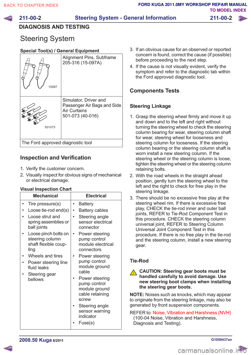
Special Tool(s) / General EquipmentAlignment Pins, Subframe
205-316 (15-097A)
15097
Simulator, Driver and
Passenger Air Bags and Side
Air Curtains
501-073 (40-016)
501073
The Ford approved diagnostic tool
Inspection and Verification
1. Verify the customer concern.
2. Visually inspect for obvious signs of mechanicalor electrical damage.
Visual Inspection Chart
Electrical
Mechanical
• Battery
• Battery cables
• Steering anglesensor electrical
connector
• Power steering pump control
module electrical
connectors
• Power steering pump control
module ground
cable
• Power steering pump control
module ground
cable retaining
screw
• Steering angle sensor warning
indicator
• Fuse(s)
• Tire pressure(s)
• Loose tie-rod end(s)
• Loose strut and
spring assemblies or
ball joints
• Loose pinch bolts on steering column
shaft flexible coup-
ling
• Wheels and tires
• Power steering line fluid leaks
• Steering gear bellows 3. If an obvious cause for an observed or reported
concern is found, correct the cause (if possible)
before proceeding to the next step.
4. If the cause is not visually evident, verify the symptom and refer to the diagnostic tab within
the Ford approved diagnostic tool.
Components Tests
Steering Linkage
1. Grasp the steering wheel firmly and move it upand down and to the left and right without
turning the steering wheel to check the steering
column bearing for wear, steering column shaft
for wear, steering wheel for looseness and
steering column for looseness. If the steering
column bearing or the steering column shaft is
worn install a new steering column. If the
steering wheel or the steering column is loose,
tighten the steering wheel or the steering column
retaining bolts.
2. With the road wheels in the straight ahead position, gently turn the steering wheel to the
left and the right to check for free play in the
steering linkage.
3. There should be no excessive free play at the steering wheel rim. If there is excessive free
play, CHECK the tie-rod inner and outer ball
joints, REFER to Tie-Rod Component Test in
this procedure. CHECK the steering column
universal joint, REFER to Steering Column
Universal Joint Component Test in this
procedure. If there is no free play in the tie-rod
and the steering column, install a new steering
gear.
Tie-Rod
CAUTION: Steering gear boots must be
handled carefully to avoid damage. Use
new steering boot clamps when installing
the steering gear boots.
NOTE: Noises such as knocks, which may appear
to originate from the steering linkage, may also be
generated by front suspension components.
REFER to: Noise, Vibration and Harshness (NVH)
(100-04 Noise, Vibration and Harshness,
Diagnosis and Testing).
G1059437en2008.50 Kuga8/2011
211-00- 2
Steering System - General Information
211-00- 2
DIAGNOSIS AND TESTING
TO MODEL INDEX
BACK TO CHAPTER INDEX
FORD KUGA 2011.0MY WORKSHOP REPAIR MANUAL
Page 1465 of 2057
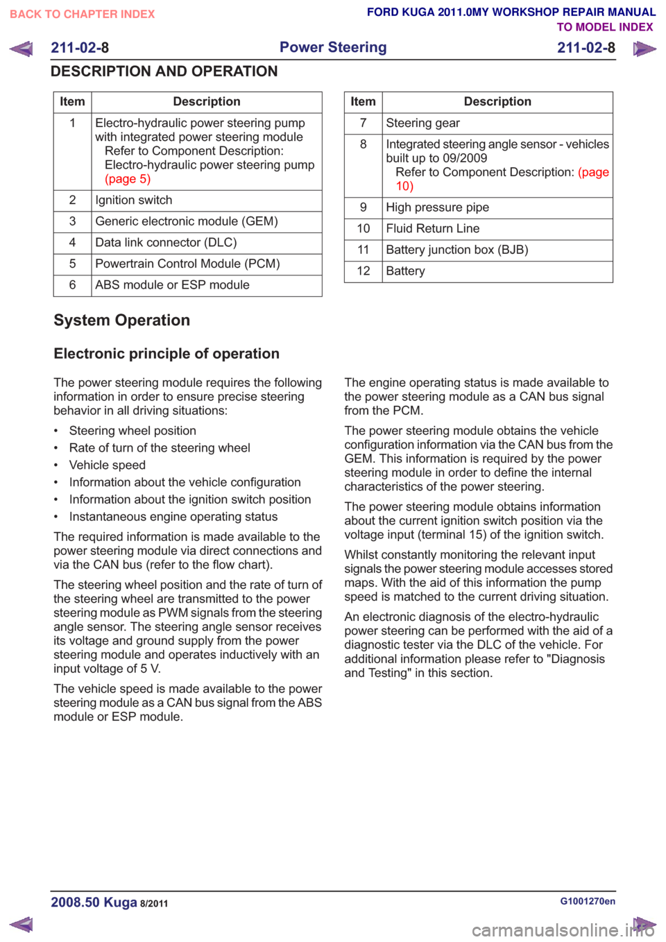
Description
Item
Electro-hydraulic power steering pump
with integrated power steering moduleRefer to Component Description:
Electro-hydraulic power steering pump
(page5)
1
Ignition switch
2
Generic electronic module (GEM)
3
Data link connector (DLC)
4
Powertrain Control Module (PCM)
5
ABS module or ESP module
6Description
Item
Steering gear
7
Integrated steering angle sensor - vehicles
built up to 09/2009RefertoComponentDescription:(page
10)
8
High pressure pipe
9
Fluid Return Line
10
Battery junction box (BJB)
11
Battery
12
System Operation
Electronic principle of operation
The power steering module requires the following
information in order to ensure precise steering
behavior in all driving situations:
• Steering wheel position
• Rate of turn of the steering wheel
• Vehicle speed
• Information about the vehicle configuration
• Information about the ignition switch position
• Instantaneous engine operating status
The required information is made available to the
power steering module via direct connections and
via the CAN bus (refer to the flow chart).
The steering wheel position and the rate of turn of
the steering wheel are transmitted to the power
steering module as PWM signals from the steering
angle sensor. The steering angle sensor receives
its voltage and ground supply from the power
steering module and operates inductively with an
input voltage of 5 V.
The vehicle speed is made available to the power
steering module as a CAN bus signal from the ABS
module or ESP module. The engine operating status is made available to
the power steering module as a CAN bus signal
from the PCM.
The power steering module obtains the vehicle
configuration information via the CAN bus from the
GEM. This information is required by the power
steering module in order to define the internal
characteristics of the power steering.
The power steering module obtains information
about the current ignition switch position via the
voltage input (terminal 15) of the ignition switch.
Whilst constantly monitoring the relevant input
signals the power steering module accesses stored
maps. With the aid of this information the pump
speed is matched to the current driving situation.
An electronic diagnosis of the electro-hydraulic
power steering can be performed with the aid of a
diagnostic tester via the DLC of the vehicle. For
additional information please refer to "Diagnosis
and Testing" in this section.
G1001270en2008.50 Kuga8/2011
211-02-
8
Power Steering
211-02- 8
DESCRIPTION AND OPERATION
TO MODEL INDEX
BACK TO CHAPTER INDEX
FORD KUGA 2011.0MY WORKSHOP REPAIR MANUAL
Page 1506 of 2057
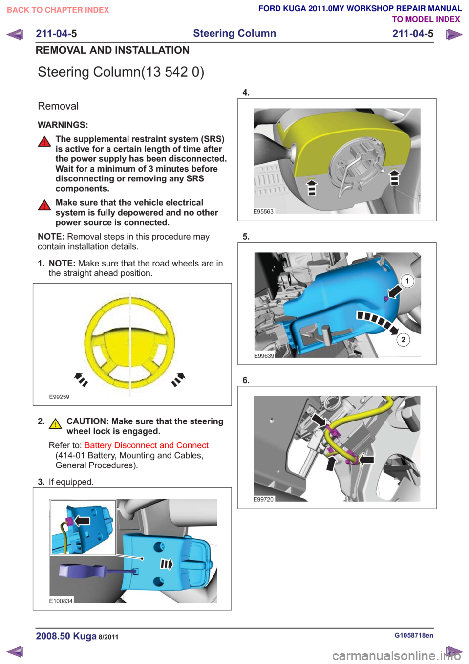
Steering Column(13 542 0)
Removal
WARNINGS:
The supplemental restraint system (SRS)
is active for a certain length of time after
the power supply has been disconnected.
Wait for a minimum of 3 minutes before
disconnecting or removing any SRS
components.
Make sure that the vehicle electrical
system is fully depowered and no other
power source is connected.
NOTE: Removal steps in this procedure may
contain installation details.
1. NOTE: Make sure that the road wheels are in
the straight ahead position.
E99259
2. CAUTION: Make sure that the steering wheel lock is engaged.
Refer to: Battery Disconnect and Connect
(414-01 Battery, Mounting and Cables,
General Procedures).
3. If equipped.
E100834
4.
E95563
5.
E99639
1
2
6.
E99720
G1058718en2008.50 Kuga8/2011
211-04- 5
Steering Column
211-04- 5
REMOVAL AND INSTALLATION
TO MODEL INDEX
BACK TO CHAPTER INDEX
FORD KUGA 2011.0MY WORKSHOP REPAIR MANUAL
Page 1520 of 2057
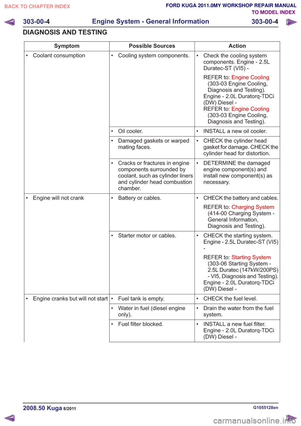
Action
Possible Sources
Symptom
• Check the cooling systemcomponents. Engine - 2.5L
Duratec-ST (VI5) -
REFER to: Engine Cooling
(303-03 Engine Cooling,
Diagnosis and Testing).
Engine - 2.0L Duratorq-TDCi
(DW) Diesel -
REFER to: Engine Cooling
(303-03 Engine Cooling,
Diagnosis and Testing).
• Cooling system components.
• Coolant consumption
• INSTALL a new oil cooler.
• Oil cooler.
• CHECK the cylinder headgasket for damage. CHECK the
cylinder head for distortion.
• Damaged gaskets or warped
mating faces.
• DETERMINE the damagedengine component(s) and
install new component(s) as
necessary.
• Cracks or fractures in engine
components surrounded by
coolant, such as cylinder liners
and cylinder head combustion
chamber.
• CHECK the battery and cables.REFER to: Charging System
(414-00 Charging System -
General Information,
Diagnosis and Testing).
• Battery or cables.
• Engine will not crank
• CHECK the starting system.Engine - 2.5L Duratec-ST (VI5)
-
REFER to: Starting System
(303-06 Starting System -
2.5L Duratec (147kW/200PS)
- VI5, Diagnosis and Testing).
Engine - 2.0L Duratorq-TDCi
(DW) Diesel -
• Starter motor or cables.
• CHECK the fuel level.
• Fuel tank is empty.
• Engine cranks but will not start
• Drain the water from the fuelsystem.
• Water in fuel (diesel engine
only).
• INSTALL a new fuel filter.Engine - 2.0L Duratorq-TDCi
(DW) Diesel -
• Fuel filter blocked.
G1055128en2008.50 Kuga8/2011
303-00-
4
Engine System - General Information
303-00- 4
DIAGNOSIS AND TESTING
TO MODEL INDEX
BACK TO CHAPTER INDEX
FORD KUGA 2011.0MY WORKSHOP REPAIR MANUAL
Page 1526 of 2057
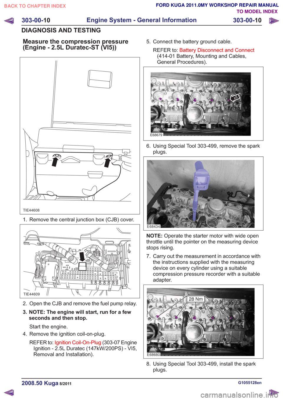
Measure the compression pressure
(Engine - 2.5L Duratec-ST (VI5))
TIE44608
1. Remove the central junction box (CJB) cover.
TIE44609
2. Open the CJB and remove the fuel pump relay.
3. NOTE: The engine will start, run for a fewseconds and then stop.
Start the engine.
4. Remove the ignition coil-on-plug.
REFER to: Ignition Coil-On-Plug (303-07 Engine
Ignition - 2.5L Duratec (147kW/200PS) - VI5,
Removal and Installation). 5. Connect the battery ground cable.
REFER to: Battery Disconnect and Connect
(414-01 Battery, Mounting and Cables,
General Procedures).
E68679
x5
6. Using Special Tool 303-499, remove the spark plugs.
E68434
NOTE: Operate the starter motor with wide open
throttle until the pointer on the measuring device
stops rising.
7. Carry out the measurement in accordance with the instructions supplied with the measuring
device on every cylinder using a suitable
compression pressure recorder with a suitable
adapter.
E68680
28 Nm
8. Using Special Tool 303-499, install the sparkplugs.
G1055128en2008.50 Kuga8/2011
303-00- 10
Engine System - General Information
303-00- 10
DIAGNOSIS AND TESTING
TO MODEL INDEX
BACK TO CHAPTER INDEX
FORD KUGA 2011.0MY WORKSHOP REPAIR MANUAL
Page 1553 of 2057
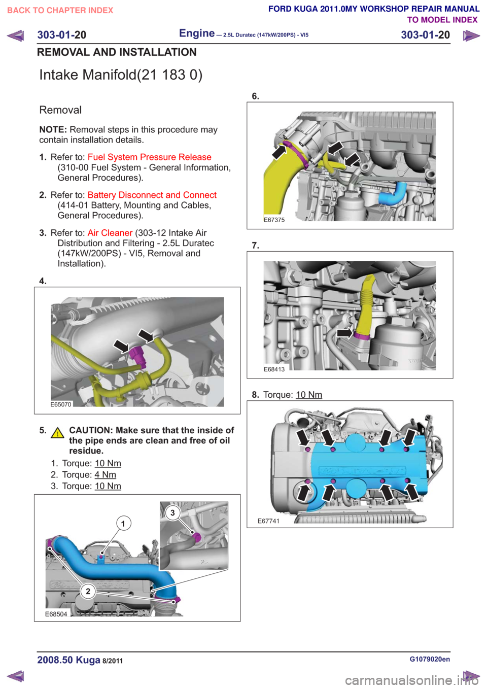
Intake Manifold(21 183 0)
Removal
NOTE:Removal steps in this procedure may
contain installation details.
1. Refer to: Fuel System Pressure Release
(310-00 Fuel System - General Information,
General Procedures).
2. Refer to: Battery Disconnect and Connect
(414-01 Battery, Mounting and Cables,
General Procedures).
3. Refer to: Air Cleaner (303-12 Intake Air
Distribution and Filtering - 2.5L Duratec
(147kW/200PS) - VI5, Removal and
Installation).
4.
E65070
5. CAUTION: Make sure that the inside of the pipe ends are clean and free of oil
residue.
1. Torque: 10Nm
2. Torque: 4Nm
3. Torque: 10Nm
2
1
3
E68504
6.
E67375
7.
E68413
8.Torque: 10Nm
E67741
G1079020en2008.50 Kuga8/2011
303-01- 20
Engine— 2.5L Duratec (147kW/200PS) - VI5303-01-
20
REMOVAL AND INSTALLATION
TO MODEL INDEX
BACK TO CHAPTER INDEX
FORD KUGA 2011.0MY WORKSHOP REPAIR MANUAL