2011 FORD KUGA turn signal
[x] Cancel search: turn signalPage 1428 of 2057
Description
Item
Battery
1
Battery junction box (BJB) in the engine
compartment
2
Generic electronic module (GEM)
3
Powertrain Control Module (PCM)
4
Instrument cluster
5
Data link connector (DLC)
6
Steering Wheel Rotation Sensor
7
ABS/ESP module or hydraulic control unit
(HCU)
8Description
Item
Combined yaw rate sensor and lateral
acceleration sensor / longitudinal
acceleration sensor
9
Front wheel sensor
10
Rear wheel sensor
11
Rear wheel sensor
12
Front wheel sensor
13
ESP switch
14
Rear brakes
15
Front brake
16
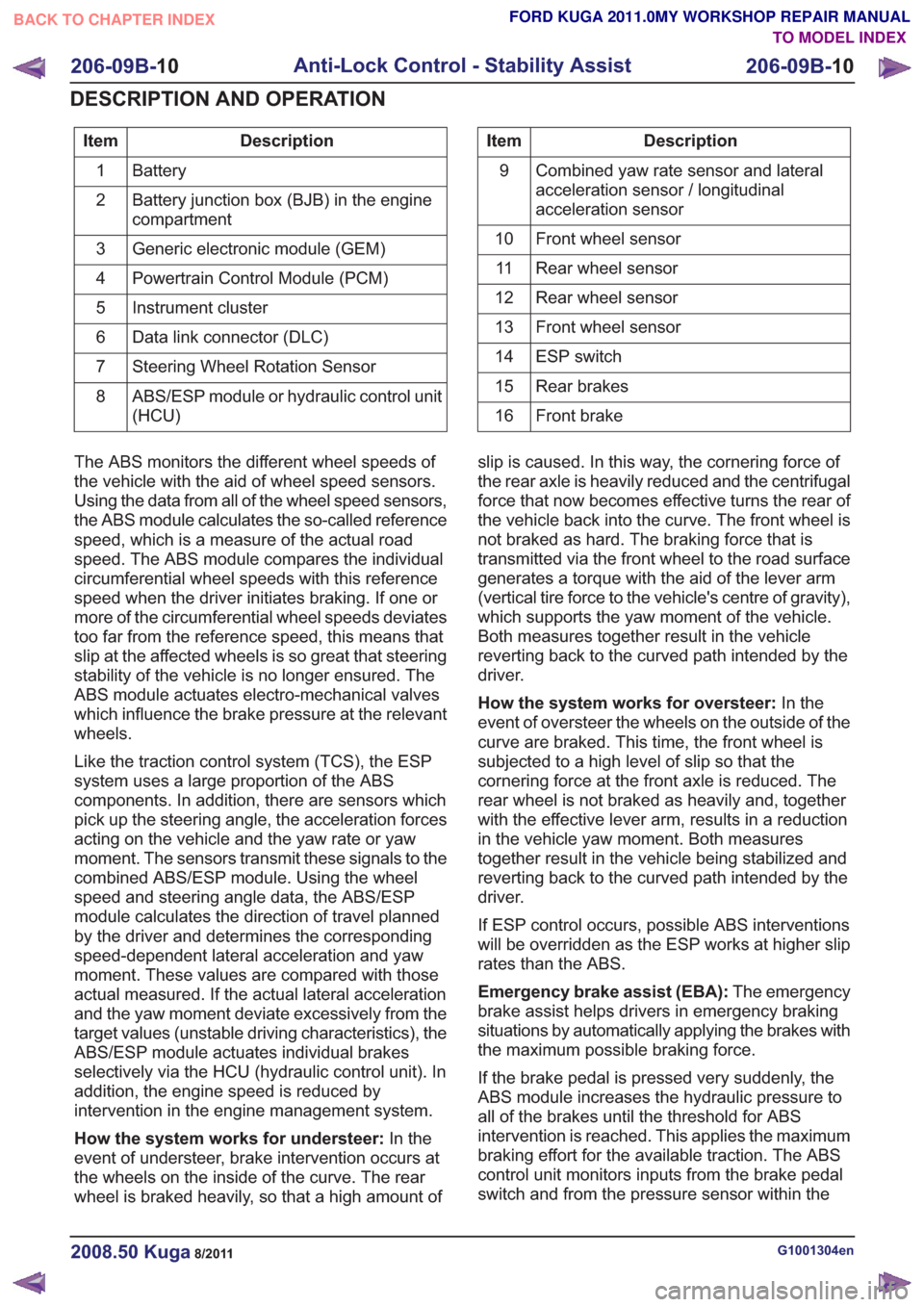
The ABS monitors the different wheel speeds of
the vehicle with the aid of wheel speed sensors.
Using the data from all of the wheel speed sensors,
the ABS module calculates the so-called reference
speed, which is a measure of the actual road
speed. The ABS module compares the individual
circumferential wheel speeds with this reference
speed when the driver initiates braking. If one or
more of the circumferential wheel speeds deviates
too far from the reference speed, this means that
slip at the affected wheels is so great that steering
stability of the vehicle is no longer ensured. The
ABS module actuates electro-mechanical valves
which influence the brake pressure at the relevant
wheels.
Like the traction control system (TCS), the ESP
system uses a large proportion of the ABS
components. In addition, there are sensors which
pick up the steering angle, the acceleration forces
acting on the vehicle and the yaw rate or yaw
moment. The sensors transmit these signals to the
combined ABS/ESP module. Using the wheel
speed and steering angle data, the ABS/ESP
module calculates the direction of travel planned
by the driver and determines the corresponding
speed-dependent lateral acceleration and yaw
moment. These values are compared with those
actual measured. If the actual lateral acceleration
and the yaw moment deviate excessively from the
target values (unstable driving characteristics), the
ABS/ESP module actuates individual brakes
selectively via the HCU (hydraulic control unit). In
addition, the engine speed is reduced by
intervention in the engine management system.
How the system works for understeer: In the
event of understeer, brake intervention occurs at
the wheels on the inside of the curve. The rear
wheel is braked heavily, so that a high amount of slip is caused. In this way, the cornering force of
the rear axle is heavily reduced and the centrifugal
force that now becomes effective turns the rear of
the vehicle back into the curve. The front wheel is
not braked as hard. The braking force that is
transmitted via the front wheel to the road surface
generates a torque with the aid of the lever arm
(vertical tire force to the vehicle's centre of gravity),
which supports the yaw moment of the vehicle.
Both measures together result in the vehicle
reverting back to the curved path intended by the
driver.
How the system works for oversteer:
In the
event of oversteer the wheels on the outside of the
curve are braked. This time, the front wheel is
subjected to a high level of slip so that the
cornering force at the front axle is reduced. The
rear wheel is not braked as heavily and, together
with the effective lever arm, results in a reduction
in the vehicle yaw moment. Both measures
together result in the vehicle being stabilized and
reverting back to the curved path intended by the
driver.
If ESP control occurs, possible ABS interventions
will be overridden as the ESP works at higher slip
rates than the ABS.
Emergency brake assist (EBA): The emergency
brake assist helps drivers in emergency braking
situations by automatically applying the brakes with
the maximum possible braking force.
If the brake pedal is pressed very suddenly, the
ABS module increases the hydraulic pressure to
all of the brakes until the threshold for ABS
intervention is reached. This applies the maximum
braking effort for the available traction. The ABS
control unit monitors inputs from the brake pedal
switch and from the pressure sensor within the
G1001304en2008.50 Kuga8/2011
206-09B- 10
Anti-Lock Control - Stability Assist
206-09B- 10
DESCRIPTION AND OPERATION
TO MODEL INDEX
BACK TO CHAPTER INDEX
FORD KUGA 2011.0MY WORKSHOP REPAIR MANUAL
Page 1430 of 2057
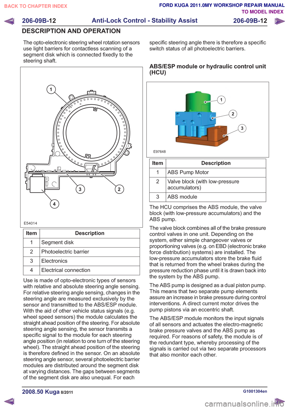
The opto-electronic steering wheel rotation sensors
use light barriers for contactless scanning of a
segment disk which is connected fixedly to the
steering shaft.
E54014
1
23
4
Description
Item
Segment disk
1
Photoelectric barrier
2
Electronics
3
Electrical connection
4
Use is made of opto-electronic types of sensors
with relative and absolute steering angle sensing.
For relative steering angle sensing, changes in the
steering angle are measured exclusively by the
sensor and transmitted to the ABS/ESP module.
With the aid of other vehicle status signals (e.g.
wheel speed sensors) the module calculates the
straight ahead position of the steering. For absolute
steering angle sensing, the sensor transmits a
specific signal to the module for each steering
angle position (in relation to one turn of the steering
wheel). The straight ahead position of the steering
is therefore defined in the sensor. On an absolute
steering angle sensor, several photoelectric barrier
modules are distributed around the segment disk
at varying distances. The gaps between segments
of the segment disk are also unequal. For each specific steering angle there is therefore a specific
switch status of all photoelectric barriers.
ABS/ESP module or hydraulic control unit
(HCU)
E97648
1
2
3
Description
Item
ABS Pump Motor
1
Valve block (with low-pressure
accumulators)
2
ABS module
3
The HCU comprises the ABS module, the valve
block (with low-pressure accumulators) and the
ABS pump.
The valve block combines all of the brake pressure
control valves in one unit. Depending on the
system, either simple changeover valves or
proportioning valves (e.g. on EBD (electronic brake
force distribution) systems) are installed. The
low-pressure accumulators store the brake fluid
that is returned from the wheel brakes during the
pressure reduction phase until it is drawn back into
the system by the ABS pump.
The ABS pump is designed as a dual piston pump.
This means that two separate pump elements
assure an increase in brake pressure during control
interventions. A direct current motor drives the
pump pistons via an eccentric shaft.
The ABS/ESP module monitors the input signals
of all sensors and actuates the electro-magnetic
brake pressure valves and the ABS pump as
required. For reasons of safety, the module is of
the redundant type, whereby processing of the
signals is carried out via two separate processors
that also monitor each other.
G1001304en2008.50 Kuga8/2011
206-09B- 12
Anti-Lock Control - Stability Assist
206-09B- 12
DESCRIPTION AND OPERATION
TO MODEL INDEX
BACK TO CHAPTER INDEX
FORD KUGA 2011.0MY WORKSHOP REPAIR MANUAL
Page 1465 of 2057
Description
Item
Electro-hydraulic power steering pump
with integrated power steering moduleRefer to Component Description:
Electro-hydraulic power steering pump
(page5)
1
Ignition switch
2
Generic electronic module (GEM)
3
Data link connector (DLC)
4
Powertrain Control Module (PCM)
5
ABS module or ESP module
6Description
Item
Steering gear
7
Integrated steering angle sensor - vehicles
built up to 09/2009RefertoComponentDescription:(page
10)
8
High pressure pipe
9
Fluid Return Line
10
Battery junction box (BJB)
11
Battery
12
System Operation
Electronic principle of operation
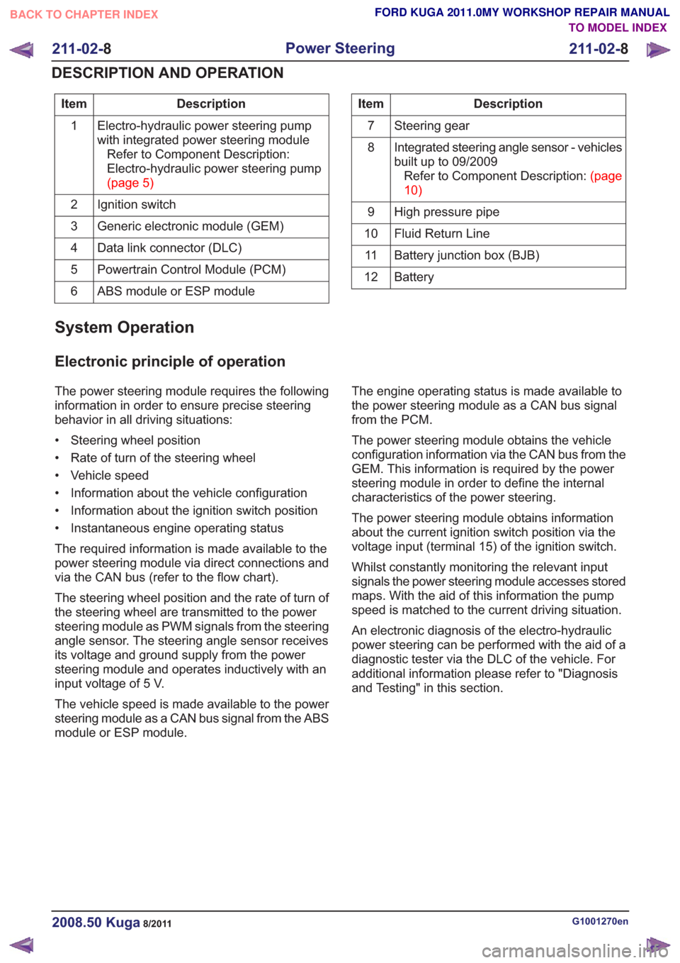
The power steering module requires the following
information in order to ensure precise steering
behavior in all driving situations:
• Steering wheel position
• Rate of turn of the steering wheel
• Vehicle speed
• Information about the vehicle configuration
• Information about the ignition switch position
• Instantaneous engine operating status
The required information is made available to the
power steering module via direct connections and
via the CAN bus (refer to the flow chart).
The steering wheel position and the rate of turn of
the steering wheel are transmitted to the power
steering module as PWM signals from the steering
angle sensor. The steering angle sensor receives
its voltage and ground supply from the power
steering module and operates inductively with an
input voltage of 5 V.
The vehicle speed is made available to the power
steering module as a CAN bus signal from the ABS
module or ESP module. The engine operating status is made available to
the power steering module as a CAN bus signal
from the PCM.
The power steering module obtains the vehicle
configuration information via the CAN bus from the
GEM. This information is required by the power
steering module in order to define the internal
characteristics of the power steering.
The power steering module obtains information
about the current ignition switch position via the
voltage input (terminal 15) of the ignition switch.
Whilst constantly monitoring the relevant input
signals the power steering module accesses stored
maps. With the aid of this information the pump
speed is matched to the current driving situation.
An electronic diagnosis of the electro-hydraulic
power steering can be performed with the aid of a
diagnostic tester via the DLC of the vehicle. For
additional information please refer to "Diagnosis
and Testing" in this section.
G1001270en2008.50 Kuga8/2011
211-02-
8
Power Steering
211-02- 8
DESCRIPTION AND OPERATION
TO MODEL INDEX
BACK TO CHAPTER INDEX
FORD KUGA 2011.0MY WORKSHOP REPAIR MANUAL
Page 1511 of 2057

Steering Column Switches – Overview
Switch unit, steering column
E98629
1
2
3
4
5
Description
Item
Left-hand switch, steering column
1
Switch unit carrier, steering column
2
Right-hand switch, steering column
3Description
Item
Steering wheel rotation sensor
Refer to: Anti-Lock Control - Stability
Assist (206-09 Anti-Lock Control -
Stability Assist, Description and
Operation).
4
Clockspring
5
Clockspring
The clockspring is designed to carry signals
between the RCM and the driver air bag module.
The clockspring is installed on the steering column,
and consists of fixed and moving parts connected
by a coiled Mylar tape with internal conducting
tracks. The Mylar tape is able to 'wind up' and
'unwind' as the steering wheel is rotated,
maintaining electrical contact at all times between
the RCM and the driver air bag module. During removal and installation or renewal of the
clockspring, pay attention to the following:
• Before installation of the clockspring, it must be
aligned according to the installation instructions.
• Make sure that the vehicle electrical system is fully depowered and no other power source is
connected.
• Secure the clockspring rotor with adhesive tape to the clockspring outer.
• The clockspring rotor must not be turned during removal or installation of the steering wheel or
the steering column switch unit.
G1030755en2008.50 Kuga8/2011
211-05- 3
Steering Column Switches
211-05- 3
DESCRIPTION AND OPERATION
TO MODEL INDEX
BACK TO CHAPTER INDEX
FORD KUGA 2011.0MY WORKSHOP REPAIR MANUAL
Page 1752 of 2057
Description
Item
Start/stop button
1
Keyless vehicle module
2
Electronic steering lock with mount -
passive key and PATS transmitter/receiver
unit
Comments:for emergency start function
3
Radio frequency receiver
Comments:Signal is only executed in GEM
4Description
Item
GEM
5
Stoplight Switch
6
TCM7
Starting deactivation relay
8
PCM
9
Starter relay
10
Starter motor
11
Battery
12
System Operation
Smart Start
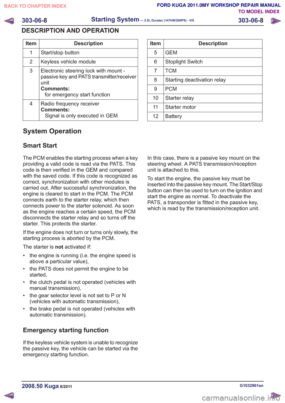
The PCM enables the starting process when a key
providing a valid code is read via the PATS. This
code is then verified in the GEM and compared
with the saved code. If this code is recognized as
correct, synchronization with other modules is
carried out. After successful synchronization, the
engine is cleared to start in the PCM. The PCM
connects earth to the starter relay, which then
connects power to the starter solenoid. As soon
as the engine reaches a certain speed, the PCM
disconnects the starter relay and so turns off the
starter. This protects the starter.
If the engine does not turn or turns only slowly, the
starting process is aborted by the PCM.
The starter is notactivated if:
• the engine is running (i.e. the engine speed is above a particular value),
• the PATS does not permit the engine to be started,
• the clutch pedal is not operated (vehicles with manual transmission),
• the gear selector level is not set to P or N (vehicles with automatic transmission),
• the brake pedal is not operated (vehicles with automatic transmission).
Emergency starting function
If the keyless vehicle system is unable to recognize
the passive key, the vehicle can be started via the
emergency starting function. In this case, there is a passive key mount on the
steering wheel. A PATS transmission/reception
unit is attached to this.
To start the engine, the passive key must be
inserted into the passive key mount. The Start/Stop
button can then be used to turn on the ignition and
start the engine as normal. To deactivate the
PATS, a transponder is fitted in the passive key,
which is read by the transmission/reception unit.
G1032961en2008.50 Kuga8/2011
303-06-
8
Starting System— 2.5L Duratec (147kW/200PS) - VI5303-06-
8
DESCRIPTION AND OPERATION
TO MODEL INDEX
BACK TO CHAPTER INDEX
FORD KUGA 2011.0MY WORKSHOP REPAIR MANUAL
Page 1784 of 2057
If one of the two APP sensors fails, then only a
proportion of the engine's power will be available
when accelerating. Top speed can nevertheless
be achieved.
If both of the APP sensors fail, the engine is
regulated to a defined speed following a plausibility
check after the BPP (brake pedal position) switch
and brake light switch have been actuated once.
The vehicle can then only be accelerated to a
defined speed.
In either case, a fault is saved in the error memory
of the PCM.
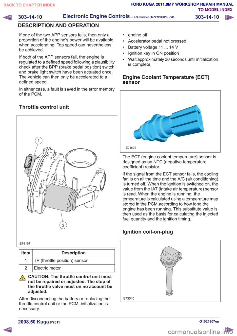
Throttle control unit
E74167
1
2
Description
Item
TP (throttle position) sensor
1
Electric motor
2
CAUTION: The throttle control unit must
not be repaired or adjusted. The stop of
the throttle valve must on no account be
adjusted.
After disconnecting the battery or replacing the
throttle control unit or the PCM, initialization is
necessary. • engine off
• Accelerator pedal not pressed
• Battery voltage 11 ... 14 V
• Ignition key in ON position
• Wait approximately 30 seconds until initialization
is complete.
Engine Coolant Temperature (ECT)
sensor
E94804
The ECT (engine coolant temperature) sensor is
designed as an NTC (negative temperature
coefficient) resistor.
If the signal from the ECT sensor fails, the cooling
fan is on all the time and the A/C (air conditioning)
is turned off. When the ignition is switched on, the
value from the IAT (intake air temperature) sensor
is read. When the engine is running, the
temperature is calculated using a temperature map
stored in the PCM according to how long the
engine has been running. This substitute value is
then used as the basis for calculating the injected
fuel quantity and the ignition timing.
Ignition coil-on-plug
E73540
G1021907en2008.50 Kuga8/2011
303-14- 10
Electronic Engine Controls— 2.5L Duratec (147kW/200PS) - VI5303-14-
10
DESCRIPTION AND OPERATION
TO MODEL INDEX
BACK TO CHAPTER INDEX
FORD KUGA 2011.0MY WORKSHOP REPAIR MANUAL
Page 1794 of 2057
than to a change in the throttle valve position. The
ignition timing also changes much more quickly.
To keep the ignition point as close as possible to
the knock limit and so optimize the efficiency of the
engine, two KS are installed in the engine, which
pick up the mechanical vibrations of the engine
and convert them into an electrical signal for the
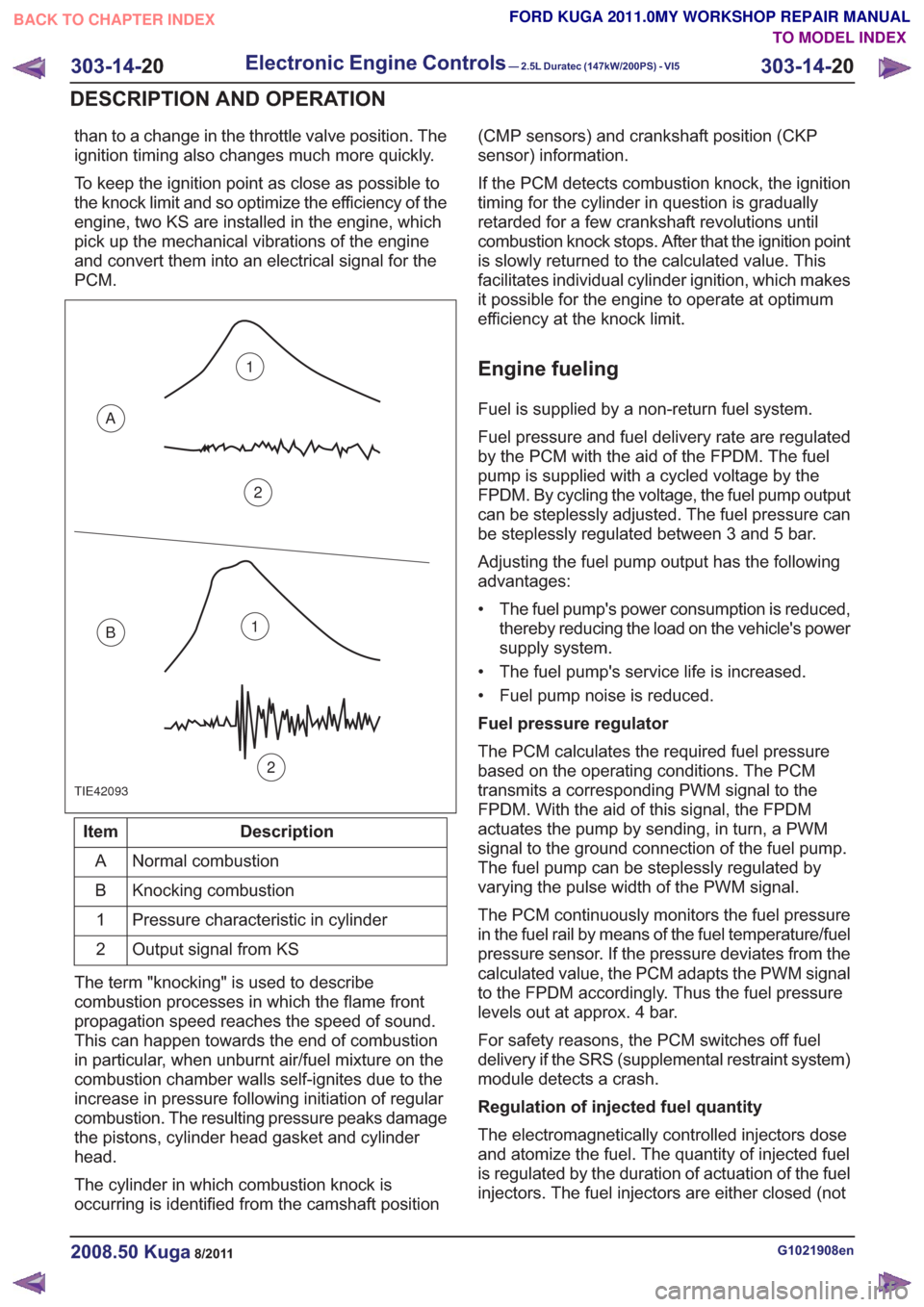
PCM.
TIE42093
1
2
A
B1
2
Description
Item
Normal combustion
A
Knocking combustion
B
Pressure characteristic in cylinder
1
Output signal from KS
2
The term "knocking" is used to describe
combustion processes in which the flame front
propagation speed reaches the speed of sound.
This can happen towards the end of combustion
in particular, when unburnt air/fuel mixture on the
combustion chamber walls self-ignites due to the
increase in pressure following initiation of regular
combustion. The resulting pressure peaks damage
the pistons, cylinder head gasket and cylinder
head.
The cylinder in which combustion knock is
occurring is identified from the camshaft position (CMP sensors) and crankshaft position (CKP
sensor) information.
If the PCM detects combustion knock, the ignition
timing for the cylinder in question is gradually
retarded for a few crankshaft revolutions until
combustion knock stops. After that the ignition point
is slowly returned to the calculated value. This
facilitates individual cylinder ignition, which makes
it possible for the engine to operate at optimum
efficiency at the knock limit.
Engine fueling
Fuel is supplied by a non-return fuel system.
Fuel pressure and fuel delivery rate are regulated
by the PCM with the aid of the FPDM. The fuel
pump is supplied with a cycled voltage by the
FPDM. By cycling the voltage, the fuel pump output
can be steplessly adjusted. The fuel pressure can
be steplessly regulated between 3 and 5 bar.
Adjusting the fuel pump output has the following
advantages:
• The fuel pump's power consumption is reduced,
thereby reducing the load on the vehicle's power
supply system.
• The fuel pump's service life is increased.
• Fuel pump noise is reduced.
Fuel pressure regulator
The PCM calculates the required fuel pressure
based on the operating conditions. The PCM
transmits a corresponding PWM signal to the
FPDM. With the aid of this signal, the FPDM
actuates the pump by sending, in turn, a PWM
signal to the ground connection of the fuel pump.
The fuel pump can be steplessly regulated by
varying the pulse width of the PWM signal.
The PCM continuously monitors the fuel pressure
in the fuel rail by means of the fuel temperature/fuel
pressure sensor. If the pressure deviates from the
calculated value, the PCM adapts the PWM signal
to the FPDM accordingly. Thus the fuel pressure
levels out at approx. 4 bar.
For safety reasons, the PCM switches off fuel
delivery if the SRS (supplemental restraint system)
module detects a crash.
Regulation of injected fuel quantity
The electromagnetically controlled injectors dose
and atomize the fuel. The quantity of injected fuel
is regulated by the duration of actuation of the fuel
injectors. The fuel injectors are either closed (not
G1021908en2008.50 Kuga8/2011
303-14- 20
Electronic Engine Controls— 2.5L Duratec (147kW/200PS) - VI5303-14-
20
DESCRIPTION AND OPERATION
TO MODEL INDEX
BACK TO CHAPTER INDEX
FORD KUGA 2011.0MY WORKSHOP REPAIR MANUAL
Page 1796 of 2057
current value is reached. The PCM then
permanently connects the heating element to earth.
The catalyst monitor sensor is used by the PCM
to measure the oxygen content in the exhaust gas
in the TWC. If all the conditions for catalyst
diagnostics are met, based on this information the
PCM can check that the TWC is working
satisfactorily. The information is also used to
improve the air/fuel mixture adjustment.
The catalyst monitor sensor is similar in function
to an HO2S. The signal transmitted by the catalyst
monitor sensor changes sharply if the oxygen
content in the exhaust gas changes. For this
reason, catalyst monitor sensors are also called
"jump lambda sensors".
Fuel tank purging
The EVAP purge valve is only actuated by the PCM
if the coolant temperature is at least 60°C.
Actuation is done ground side by means of a PWM
signal. This makes it possible to have the full range
of opening widths, from fully closed to fully open.
The PCM determines from the operating conditions
when and how wide to open the EVAP tank purge
valve. If the EVAP purge valve is opened, the
engine sucks in ambient air through the activated
charcoal in the evaporative emission canister as
a result of the vacuum in the intake manifold. In
this way the adsorbed hydrocarbons are led to the
combustion chamber of the engine.
The EVAP tank purge valve is not actuated and
system cleaning is interrupted if the engine
switches to idle and/or a closed-loop control
process is initiated.
Power (battery voltage) is supplied via the
Powertrain Control Module relay in the BJB. The
solenoid coil resistance is between 17 and 24 ohms
at 20°C.
Engine speed control
The APP sensor provides the PCM with information
about the driver's request for acceleration.
The throttle control unit receives a corresponding
input signal from the PCM. An electric motor then
moves the throttle valve shaft by means of a set
of gears. The position of the throttle is continuously
recorded by the TP sensor. Information on throttle
position is processed and monitored by the PCM.
The TP sensor comprises two potentiometers.
These work in opposite ways to each other. In one
potentiometer, the resistance increases when the
throttle is opened, in the other it decreases. Thisallows the operation of the potentiometers to be
checked. The signal from the TP sensor is
amplified in the lower range (idle to a quarter open)
by the PCM to enable more precise control of the
throttle in this range. This is necessary because
the engine is very sensitive to changes in throttle
angle in this throttle opening range.
With the throttle valve position kept constant, the
ignition angle and the injected fuel quantity are
then varied to meet the torque demands.
Depending on the operating state of the engine, a
change in the position of the throttle flap may not
be necessary when the APP sensor changes.
If a fault develops in the throttle control unit, a
standby function is executed. This standby function
allows a slight opening of the throttle flap, so that
enough air passes through to allow limited engine
operation. For this purpose, there is a throttle flap
adjustment screw on the throttle housing. The
return spring closes the throttle flap until the stop
of the toothed segment touches the stop screw. In
this way a defined throttle flap gap is formed for
limp home mode.
The stop screw has a spring loaded pin, which
holds the throttle flap open for limp home mode.
In normal operating mode, this spring loaded pin
is pushed in by the force of the electric motor when
the throttle flap must be closed past the limp home
position (e.g. for idle speed control or overrun
shutoff).
Oil monitoring
The engine does not have an oil pressure
switch.
The oil level and oil quality are calculated.
Calculating the engine oil level
The oil level is determined by continuous
measurement of the capacitance (i.e. the ability to
store an electrical charge) between the two
capacitive elements of the engine oil
level/temperature/quality sensor. The different oil
levels cause the capacitance between the elements
to change. The data are recorded by the PCM and
converted into an oil level value. Temporary
fluctuations in oil level are automatically filtered out
by the PCM.
Calculating oil quality
The PCM calculates the oil quality from the oil level
measurement and the oil temperature measured
by the sensor, plus the engine speed and the
average fuel consumption. The driver is informed
about when an oil change is due.
G1021908en2008.50 Kuga8/2011
303-14- 22
Electronic Engine Controls— 2.5L Duratec (147kW/200PS) - VI5303-14-
22
DESCRIPTION AND OPERATION
TO MODEL INDEX
BACK TO CHAPTER INDEX
FORD KUGA 2011.0MY WORKSHOP REPAIR MANUAL