2011 FORD KUGA front
[x] Cancel search: frontPage 402 of 2057

36.
On both sides.
Refer to: B-Pillar Trim Panel (501-05 Interior
Trim and Ornamentation, Removal and
Installation).
37. On both sides.
Refer to: C-Pillar Trim Panel (501-05 Interior
Trim and Ornamentation, Removal and
Installation).
38. On both sides.
Refer to: D-Pillar Trim Panel (501-05 Interior
Trim and Ornamentation, Removal and
Installation). 39.
Refer to: Loadspace Trim Panel LH (501-05
Interior Trim and Ornamentation, Removal
and Installation).
Refer to: Loadspace Trim Panel RH (501-05
Interior Trim and Ornamentation, Removal
and Installation).
40. Remove the rear lamps.
41. On both sides.
Refer to: Front Seat (501-10 Seating, Removal
and Installation).
42. Refer to: Rear Seat Backrest (501-10 Seating,
Removal and Installation).
43. Refer to: Rear Seat Cushion (501-10 Seating,
Removal and Installation).
44. G1065595en
2008.50 Kuga 8/2011 418-02-13
Wiring Harnesses
418-02-13
REMOVAL AND INSTALLATIONTO MODEL INDEX
BACK TO CHAPTER INDEX
FORD KUGA 2011.0MY WORKSHOP REPAIR MANUAL
Page 426 of 2057

Engine Compartment Wiring Harness
Removal
NOTE:
Removal steps in this procedure may
contain installation details.
1. 2.
Refer to: Headlamp Assembly (417-01 Exterior
Lighting, Removal and Installation).
3. Refer to: Wheel and Tire (204-04 Wheels and
Tires, Removal and Installation).
4. Refer to: Fender Splash Shield (501-02 Front
End Body Panels, Removal and Installation).
5. Refer to: Front Bumper Cover (501-19 Bumpers,
Removal and Installation).
6. Torque: 10 Nm
7.
Torque: 10 Nm
G1065599en
2008.50 Kuga 8/2011 418-02-37
Wiring Harnesses
418-02-37
REMOVAL AND INSTALLATIONTO MODEL INDEX
BACK TO CHAPTER INDEX
FORD KUGA 2011.0MY WORKSHOP REPAIR MANUALE102365
Page 443 of 2057

Anti-Theft Alarm Horn with Integral Battery
Removal
1.
Refer to: Cowl Panel Grille (501-02 Front End
Body Panels, Removal and Installation).
2. 3.
Installation
1.
To install, reverse the removal procedure. G1065602en
2008.50 Kuga 8/2011 419-01A-11
Anti-Theft - Active
419-01A-11
REMOVAL AND INSTALLATIONTO MODEL INDEX
BACK TO CHAPTER INDEX
FORD KUGA 2011.0MY WORKSHOP REPAIR MANUALE114592 E114593
Page 456 of 2057

Description
Item
HS CAN
1
DLC2
MS CAN
3
Instrument cluster (gateway)
4
Front windshield wiper motors
5
GEM6
Rear window wiper motors
7
Indicator/heated windshield
8
Indicator/heated rear window
9 Description
Item
Mini-liftgate latch motor
10
Liftgate latch motor
11
Electric booster Heater
12
Front wiper windscreen washer pump
13
Rear wiper windscreen washer pump
14
Headlamp
15
Courtesy Lighting
16
Alarm horn
17
System Operation
GEM.
The following functions are controlled or performed
by the GEM at a battery voltage of between 9 and
16 volts:
• Current distribution
• Battery charging (Smart Charge)
• Ignition overload protection
• Headlamp switch-off delay
• Turn signals
• Interior lighting
• Heated windscreen
• Heated rear window and heated external mirrors
• Ambient air temperature
• Brake fluid level
• Automatic headlamps
• Combined rain sensor/light sensor
• Windshield wash/wipe system
• Speed control – reads the speed control switches andtransmits signals on the CAN data bus
• central door locking – transmits signals on the CAN data bus
• Anti-theft
• Electric booster Heater
• Climate control
• Parking brake –(monitors the switch and transmits the signal
on the CAN data bus
• Communication via the medium-speed CAN data bus Component Description
Battery charging (Smart Charge)
In addition to the familiar functions, the Smart
Charge system also performs the following
functions:
•
Automatic deactivation of non-critical high power
electrical consumers when the battery voltage
is low in order to reduce the level of current
drawn.
• Automatic activation of non-critical high power electrical consumers when the battery voltage
is excessively high in order to protect
components which are sensitive to increased
voltages.
The battery charging current is optimized through
continuous calculation of the battery temperature
and monitoring of the alternator output voltage.
The alternator load is signaled to the PCM
(powertrain control module) in order to provide it
with an early indication when an electric component
is to be switched on or off, thereby also providing
information about imminent changes to the amount
of torque demanded by the alternator. By
evaluating this information the PCM is capable of
increasing the stability of the engine under idling.
The two remaining functions of the Smart Charge
system are controlled by the GEM. G1030788en
2008.50 Kuga 8/2011 419-10-6
Multifunction Electronic Modules
419-10-6
DESCRIPTION AND OPERATIONTO MODEL INDEX
BACK TO CHAPTER INDEX
FORD KUGA 2011.0MY WORKSHOP REPAIR MANUAL
Page 458 of 2057

Turn signals
Description
Item
External mirror housing
1
Turn signals
2
The GEM switches the direction indicators and the
direction indicator side repeaters on.
The GEM sends a signal to the instrument cluster
via the CAN bus to switch on the relevant turn
indicator and the acoustic signal.
The signals from the hazard flasher switch and
from the multifunction switch are transmitted to the
GEM via a wiring connection.
The turn signals and the warning lamp flash at a
specified frequency and, in the case of failure of a
turn signal, the frequency is doubled.
The turn signal lamps also have a one-touch lane
change function. If the multifunction lever is
pressed just slightly then the relevant turn signal
lamp is actuated 3 times by the GEM.
Interior lighting
Depending on the vehicle specification, the interior
lighting includes:
• Left and right-hand footwell lamps
• Overhead lights at front and rear
Depending on the vehicle specification, the
switchable interior lighting includes:
• Map lights
• Mirror lights in sun visors
• Glove compartment lamp
• Luggage compartment lamp
The front and rear overhead lights are switched on
by the GEM. The interior lighting is switched on if one of the
following conditions is satisfied:
One of the vehicle's doors is opened.
The ignition key is in the "0" or "I" position and the
vehicle is unlocked.
The ignition key is turned from the "II" to the "I" or
"0" position.
The interior lighting is switched off when all of the
doors are closed and one of the following
conditions is satisfied:
• 25 seconds have elapsed since the last door
was closed.
• The ignition key is turned from the "0" or "I" to the "II" position.
• The ignition key is in the "0" or "I" position while the vehicle is locked.
The dimmer function is not used if the interior
lighting is switched off via the battery protection
function.
Heated windscreen
The heated windshield is switched on by the GEM
under the following conditions:
• The heated windshield switch is operated, the ignition switch is in position "II" and the charge
warning lamp is switched off.
• The "Defrost" function of the two-zone air conditioning has been activated, the ignition
switch is in the position "II" and the charge
warning lamp is off.
• The battery voltage has exceeded 16 V for more
than 20 seconds (power management strategy).
Manual requests for switching off the heated
windshield by pressing the switch are ignored
at this time.
• The engine was started at an outside air temperature below 4°C and an engine
temperature below 65°. Manual requests for
switching off the heated windshield by pressing
the switch are accepted.
NOTE: If the battery voltage returns to the normal
range, the disabling of the heated windshield is
switched off. It is then switched off.
The heated windshield is switched off by the GEM
under the following conditions: G1030788en
2008.50 Kuga 8/2011 419-10-8
Multifunction Electronic Modules
419-10-8
DESCRIPTION AND OPERATIONTO MODEL INDEX
BACK TO CHAPTER INDEX
FORD KUGA 2011.0MY WORKSHOP REPAIR MANUAL12E98941
Page 462 of 2057

Output signals
SWITCH the wiper switch to the "intermittent""
position to test the output signals. PRESSING the
heated rear window switch activates the output
signals in the following order:
a.
Left-hand turn signal
b. Right-hand turn signal
c. Main beam
d. Dipped beam
e. Windshield wiper stage I
f. Windshield wiper stage II
g. Heated rear windshield
h. Heater blower motor
i. Headlamp washer system (vehicles with HID headlamps)
j. Electric booster heater (if fitted)
k. Autolamps (position lamps only if fitted)
l. Alarm horn (vehicles with alarm system)
m. Rear window wiper
n. Heated front window relay
When the heated rear window switch is pressed
again, the test of the relevant signal is terminated.
When the heated rear window switch is pressed
once more, the test for the next signal in the list is
started.
End service mode
The GEM automatically ends service mode 20
seconds after the last input or at a driving speed
of over 7km/h. However, service mode can be
manually ended at any time by proceeding as
follows:
• PRESS and HOLD the switch of the heated rear
window
• SWITCH OFF the ignition.
• RELEASE the switch of the heated rear window
3 signals sound and the turn signal lamps illuminate
to indicate that service mode has ended.
Reset service mode
If, after completion of service mode, some functions
do not operate or do not operate properly, check
the following functions:
• Instrument cluster illumination, side marker lamps (side lights) and licence plate lamp in
automatic headlamps mode
• Rear wiper
• Headlamp washer assembly
• Electric booster heater • Alarm horn
• Heated windshield
If one or more of the listed functions is not OK, it's
possible that the cause of the fault is due to not
exiting service mode properly. To reactivate the
functions correctly, perform the following steps:
1. Switch off the ignition.
2. SWITCH OFF the switch for the windscreen
wash/wipe system
3. OPERATE the switch of the heated rear window
and HOLD IT THERE
4. SWITCH ON the ignition.
5. RELEASE the heated rear window switch (an acoustic signal will sound if activation has been
performed correctly)
6. SWITCH the windscreen wash/wipe switch to the "Intermittent wipe" position
7. OPERATE the heated rear window switch 6 times (the main beam headlamps switch on and
off automatically)
8. SWITCH OFF the switch for the windscreen wash/wipe system
9. OPERATE the switch of the heated rear window
and HOLD IT THERE
10. Switch off the ignition.
11. RELEASE the heated rear window switch (three
acoustic signals will sound if activation has been
performed correctly)
After completion of the work, check all the
functions.
Inspection and Checking
NOTE: The generic electronic module (GEM) is
integrated into the central junction box (CJB).
1. VERIFY customer concern.
2. Visually CHECK for any obvious mechanical or electrical damage.
NOTE: Ensure correct locking of the wiring harness
connector.
Visual Inspection Electrical
Fuses
Wiring harness Connectors G1055084en
2008.50 Kuga 8/2011 419-10-12
Multifunction Electronic Modules
419-10-12
DIAGNOSIS AND TESTINGTO MODEL INDEX
BACK TO CHAPTER INDEX
FORD KUGA 2011.0MY WORKSHOP REPAIR MANUAL
Page 1158 of 2057

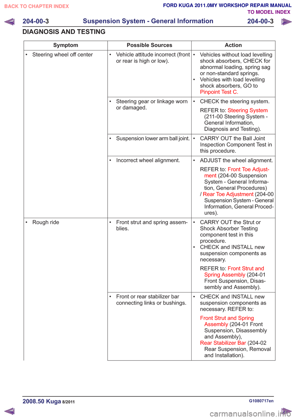
Action
Possible Sources
Symptom
• Vehicles without load levellingshock absorbers, CHECK for
abnormal loading, spring sag
or non-standard springs.
• Vehicles with load levelling shock absorbers, GO to
Pinpoint Test C.
• Vehicle attitude incorrect (front
or rear is high or low).
• Steering wheel off center
• CHECK the steering system.REFER to: Steering System
(211-00 Steering System -
General Information,
Diagnosis and Testing).
• Steering gear or linkage worn
or damaged.
• CARRY OUT the Ball JointInspection Component Test in
this procedure.
• Suspension lower arm ball joint.
• ADJUST the wheel alignment.REFER to: Front Toe Adjust-
ment (204-00 Suspension
System - General Informa-
tion, General Procedures)
/ Rear Toe Adjustment (204-00
Suspension System - General
Information, General Proced-
ures).
• Incorrect wheel alignment.
• CARRY OUT the Strut orShock Absorber Testing
component test in this
procedure.
• CHECK and INSTALL new suspension components as
necessary.
REFER to: Front Strut and
Spring Assembly (204-01
Front Suspension, Disas-
sembly and Assembly).
• Front strut and spring assem-
blies.
• Rough ride
• CHECK and INSTALL newsuspension components as
necessary. REFER to:
Front Strut and Spring Assembly (204-01 Front
Suspension, Disassembly
and Assembly),
Rear Stabilizer Bar (204-02
Rear Suspension, Removal
and Installation).
• Front or rear stabilizer bar
connecting links or bushings.
G1080717en2008.50 Kuga8/2011
204-00- 3
Suspension System - General Information
204-00- 3
DIAGNOSIS AND TESTING
TO MODEL INDEX
BACK TO CHAPTER INDEX
FORD KUGA 2011.0MY WORKSHOP REPAIR MANUAL
Page 1159 of 2057

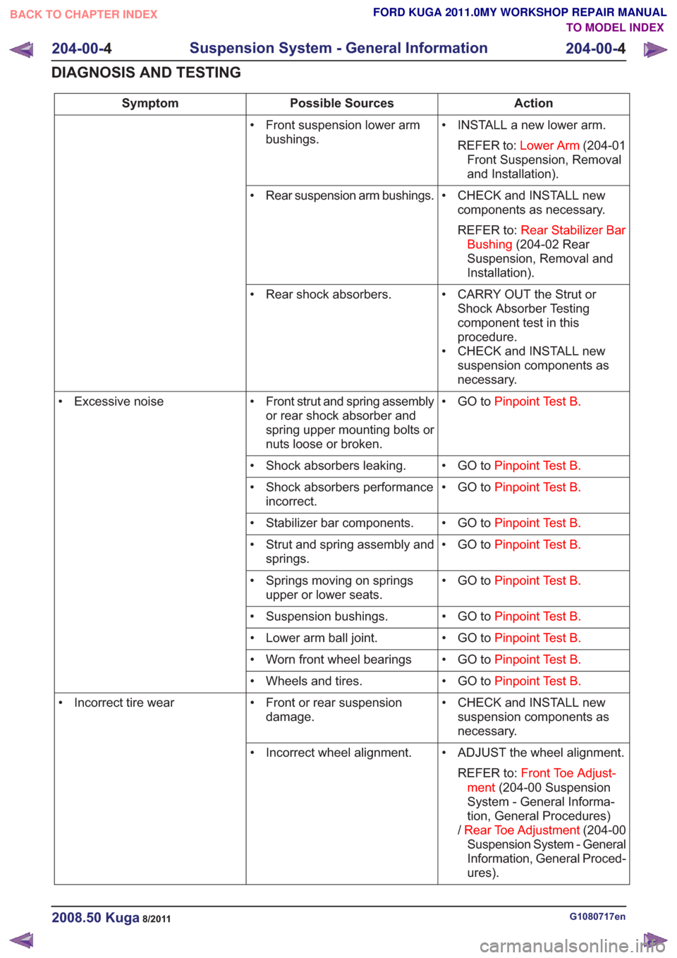
Action
Possible Sources
Symptom
• INSTALL a new lower arm.REFER to: Lower Arm (204-01
Front Suspension, Removal
and Installation).
• Front suspension lower arm
bushings.
• CHECK and INSTALL newcomponents as necessary.
REFER to: Rear Stabilizer Bar
Bushing (204-02 Rear
Suspension, Removal and
Installation).
• Rear suspension arm bushings.
• CARRY OUT the Strut orShock Absorber Testing
component test in this
procedure.
• CHECK and INSTALL new suspension components as
necessary.
• Rear shock absorbers.
• GO toPinpoint Test B.
• Front strut and spring assembly
or rear shock absorber and
spring upper mounting bolts or
nuts loose or broken.
• Excessive noise
• GO toPinpoint Test B.
• Shock absorbers leaking.
• GO toPinpoint Test B.
• Shock absorbers performance
incorrect.
• GO toPinpoint Test B.
• Stabilizer bar components.
• GO toPinpoint Test B.
• Strut and spring assembly and
springs.
• GO toPinpoint Test B.
• Springs moving on springs
upper or lower seats.
• GO toPinpoint Test B.
• Suspension bushings.
• GO toPinpoint Test B.
• Lower arm ball joint.
• GO toPinpoint Test B.
• Worn front wheel bearings
• GO toPinpoint Test B.
• Wheels and tires.
• CHECK and INSTALL newsuspension components as
necessary.
• Front or rear suspension
damage.
• Incorrect tire wear
• ADJUST the wheel alignment.REFER to: Front Toe Adjust-
ment (204-00 Suspension
System - General Informa-
tion, General Procedures)
/ Rear Toe Adjustment (204-00
Suspension System - General
Information, General Proced-
ures).
• Incorrect wheel alignment.
G1080717en2008.50 Kuga8/2011
204-00-
4
Suspension System - General Information
204-00- 4
DIAGNOSIS AND TESTING
TO MODEL INDEX
BACK TO CHAPTER INDEX
FORD KUGA 2011.0MY WORKSHOP REPAIR MANUAL