2011 FORD KUGA Starting
[x] Cancel search: StartingPage 1836 of 2057

• Selector lever position and selector leverposition display
• Fluid leakage
• Transmission fluid level check
• Transmission fluid quality check
• Modification/retrofitting
• Mechanical damage to the transmission
When inspecting connectors, remember that the
plugs may only be disconnected when they are not
energized.
The transaxle electronics may be destroyed by
static charge. To prevent damage, it must be
ensured that the technician complies with the
corresponding safeguards.
NOTE: Refer to the service literature for an exact
description of these safeguards.
Towing the vehicle
E66463
In general, vehicles with the AW55 transaxle can
be towed. Vehicles must never be towed
backwards.
As a result of the reduced lubrication of the
transaxle during towing, the following must be
remembered:
• The selector lever must be in the 'N' position.
• The maximum towing speed must not exceed 50 km/h.
• The maximum towing distance must not exceed 50 kilometers.
Push-starting the Vehicle
No torque is transmitted when towing or pushing
the vehicle. For this reason, vehicles with an
automatic transaxle cannot and must not be
tow-started or push-started.
Jump-starting the Vehicle
CAUTION: When jump-starting the vehicle
using a jumper lead there may be voltage
peaks. These may destroy the transaxle
electronics.
NOTE: When jump-starting the vehicle, the external
battery must remain connected for several minutes.
The voltage peaks dissipate after a few minutes.
Only then may the external battery be disconnected
without the risk of damage.
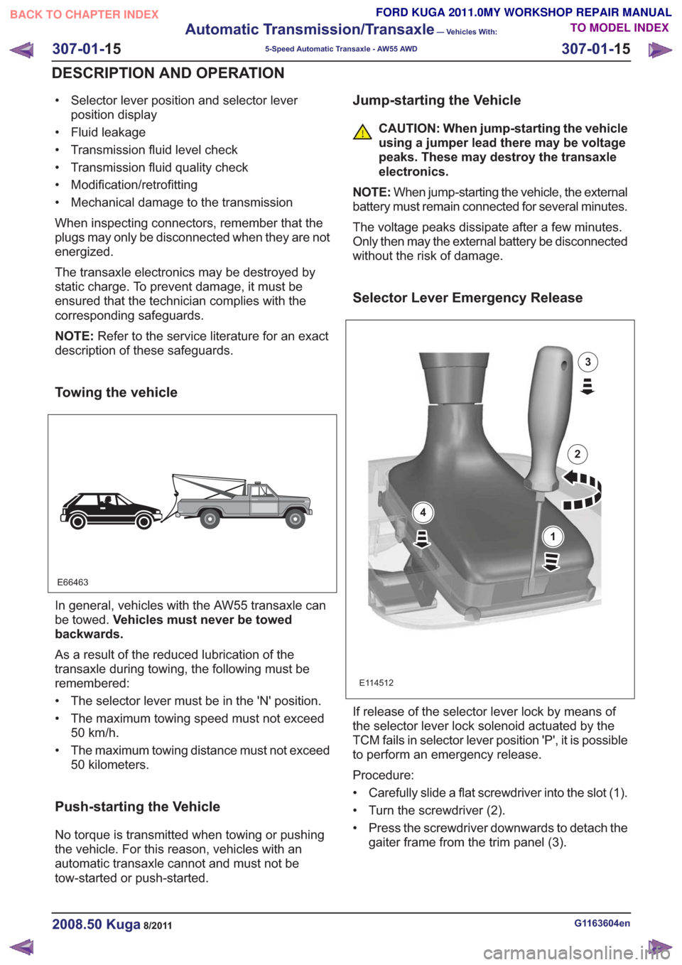
Selector Lever Emergency Release
E114512
1
2
3
4
If release of the selector lever lock by means of
the selector lever lock solenoid actuated by the
TCM fails in selector lever position 'P', it is possible
to perform an emergency release.
Procedure:
• Carefully slide a flat screwdriver into the slot (1).
• Turn the screwdriver (2).
• Press the screwdriver downwards to detach the gaiter frame from the trim panel (3).
G1163604en2008.50 Kuga8/2011
307-01- 15
Automatic Transmission/Transaxle
— Vehicles With:
5-Speed Automatic Transaxle - AW55 AWD
307-01- 15
DESCRIPTION AND OPERATION
TO MODEL INDEX
BACK TO CHAPTER INDEX
FORD KUGA 2011.0MY WORKSHOP REPAIR MANUAL
Page 1850 of 2057

To exactly determine the activation points of the
gear shifts and torque converter lockup on the
basis of the type of driving mode chosen, the TCM
receives the following information:
• Selected transmission range (TR sensor)
• Selected driving mode (normal/sport/select-shift)
• Transmission input shaft speed (TSS sensor)
• Transmission output shaft speed (OSS sensor)
• Transmission fluid temperature (TFT sensor)
• The engine speed and the torque as well as thethrottle plate opening - from the PCM via the
CAN databus
• Actuation of accelerator – from the PCM via the CAN databus
• The coolant temperature – from the PCM via the CAN databus
• Road speed – from the ABS module via the CAN databus
• Actuation of brake pedal – from the PCM via the CAN databus
Gearshift control
Adaptation
The TCM monitors every shift operation in all
driving conditions to make even and smooth gear
shifts possible. This is done by the control module,
which either lowers or increases the hydraulic line
pressure during gearshifts.
The changed pressure values are stored in the
control module memory after the engine is switched
off and retrieved during engine starting. This
improves the shift comfort and extends the service
life.
Full adaptability occurs when the following criteria
are met:
• Throttle plate opening is constant.
• Transmission fluid temperature between 65 °Cand 110 °C.
Shifting from 'P' to another transmission
range
To be able to move the selector lever from 'P' into
another transmission range, the ignition must be
switched on and the brake pedal pressed (stoplamp
switch on). The TCM detects the position of the
brake pedal via the CAN data bus and the engaged
transmission range from the TR sensor. Based on this information, the TCM transmits a
signal to the select-shift switch module. This
activates the brake shift interlock actuator in the
selector lever assembly.
When the brake shift interlock actuator is activated,
the locking pin is retracted so that another
transmission range can be selected.
The brake shift interlock actuator is deactivated
when the ignition is switched off. It is mechanically
locked when the gear selector lever is in 'P'.
Automatic transmission, selector lever in
position "D".
The TCM adapts the shift points to match the
driving conditions. Normally the TCM is in adaptive
mode and gear changes take place adapted to the
driving conditions. If special driving conditions are
detected, the TCM switches to predefined
characteristics.
When driving with normal acceleration, the TCM
uses a preset shift program which is optimized for
economical driving.
This shift program is suitable for "normal" driving
and delivers early upward changes and torque
converter lockup. Furthermore, the transmission
fluid pressure is adapted to make smooth
engagement of the gears possible.
Sport mode, selector lever in position "S"
The transmission switches from automatic
operation into sport mode. In this mode the TCM
switches to another set of characteristic curves.
These characteristic curves for control of the gear
changes are adapted to sporting calculations (e.g.
gear change at higher engine speed).
In the sport mode shift program the shift points are
set so that good performance is offered. Changing
down occurs at lower engine speeds.
Manual gear changes (select-shift mode) can be
made in sport mode by moving the selector lever
in the (+) or (-) direction.
Changing gear in select-shift mode
If you move the selector lever to 'S', the automatic
transaxle remains hydraulically in 'D' position. If
you move the gear selector lever forwards (-), the
G1163605en2008.50 Kuga8/2011
307-01-
29
Automatic Transmission/Transaxle
— Vehicles With:
5-Speed Automatic Transaxle - AW55 AWD
307-01- 29
DESCRIPTION AND OPERATION
TO MODEL INDEX
BACK TO CHAPTER INDEX
FORD KUGA 2011.0MY WORKSHOP REPAIR MANUAL
Page 1865 of 2057

Description
Item
ABS5
Cruise control
6
Select-shift switch module
7
PCM
8
Selector lever lock
9
PWM solenoid valve – shift pressure (SLS)
10
PWM solenoid valve for main line pressure
(SLT)
11
PWM- solenoid valve – TCC (SLU)
12Description
Item
Shift solenoid S1 (open when dormant)
13
Shift solenoid S2 (closed when dormant)
14
Shift solenoid S3 (closed when dormant)
15
Shift solenoid S4 (open when dormant)
16
Shift solenoid S5 (closed when dormant)
17
The TSS sensor
18
The OSS sensor
19
The TFT sensor
20
TR sensor in TCM
21
Input signals
Hard wired
• Item 18: ISS (input shaft speed) sensor
– Supplies information on the transmissioninput shaft speed. Used for calculations, for
instance the shift process, checking the
torque converter lockup and for diagnosis of
the hydraulic/mechanical operations in the
transmission.
• Item 19: OSS sensor – Supplies information on the transmissionoutput shaft speed. Used for calculations, for
instance the vehicle speed and for diagnosis
of the hydraulic/mechanical operations in the
transmission.
• Item 20: TFT sensor – Supplies information on the transmission fluidtemperature. This information is used to
adjust the shift times and the fluid pressure.
• Item 21: TR sensor – Supplies the TCM with the information on thechosen transmission range. Starting is only
possible when the selector lever is in the P
or N position. The sensor is a permanent
magnet which creates a magnetic field over
the different Hall sensors and in this way
creates a specific voltage for each shift
operation.
Via the LIN data bus
• Item 7: Selector lever module (select-shift module)
– Indicates that the selector lever is locked inposition P and supplies information on the
sport mode status. Also transmits a control
signal during select-shift gear changes and
supplies information on the fault status in the selector lever module, so that the fault codes
in the module can be stored as required.
Via the CAN data bus
• Item 4: PCM – Stop light switch ON/OFF, is used by theTCC.
– Coolant temperature, used for diagnosis of the transmission temperature sensor and for
activating the catalytic converter.
– Engine speed >400 rpm = engine running. Used for starting the transmission fluid
pressure and diagnosis functions.
– Engine rpm. Used for checking the torque converter slip and the pressure build-up,
which have an effect on the shift comfort.
– Kickdown. If the accelerator pedal is pressed down and the throttle plate is wide open, the
PCM transmits a kickdown signal to the TCM.
– Current engine speed, used to check the line pressure of the transmission.
– Throttle plate opening, used to calculate the gear changes. During sport mode and
kickdown.
– Accelerator pedal position, used to calculate the shift threshold timings.
• Item 5: ABS module – Supplies information on the vehicle speedand also on the difference in speed between
the left-hand and right-hand wheels. Prevents
changing up if the speed difference is greater
than 40 km/h, to protect the differential in the
transmission.
• Item 6: Vehicle speed control system – Is used to calculate the acceleration,depending on the position of the resume and
set buttons.
G1163605en2008.50 Kuga8/2011
307-01- 44
Automatic Transmission/Transaxle
— Vehicles With:
5-Speed Automatic Transaxle - AW55 AWD
307-01- 44
DESCRIPTION AND OPERATION
TO MODEL INDEX
BACK TO CHAPTER INDEX
FORD KUGA 2011.0MY WORKSHOP REPAIR MANUAL
Page 2025 of 2057

Electronic Leak Detection
1.Refer to: Air Conditioning (A/C) System Health
and Safety Precautions (100-00 General
Information, Description and Operation).
2. WARNINGS:
Before starting leak detection, make
sure that the area where it is to be done
is well ventilated. If the surrounding air
is contaminated with refrigerant gas, the
leak detector will indicate this gas all
the time. Odors from other chemicals
such as antifreeze, diesel fuel, disc
brake cleaner, or other cleaning
solvents can cause the same problem.
Prevent air movement while performing
leak detection.
The refrigerant identification equipment
must be used before attaching the
manifold gauge set. Otherwise the
manifold gauge set may become
contaminated. Contaminated refrigerant
must be disposed of as special waste.
Follow the manufacturer's instructions
when working with the service unit.
NOTE: At 24°C with the engine switched off,
both manifold gauges should show 4.1 to 5.5
bar.
Attach the manifold gauge set to the service
gauge port valves.
3. For the leak test, close the manual valves on
the gauge set.
4. If little or no pressure is indicated, charge the
system with approx. 300g of refrigerant. Refer
to: Air Conditioning System - Evacuate and
Refill.
5. Use the R-134a Automatic Calibration Halogen
Leak Detector to leak test the refrigerant system.
Follow the instructions included with leak
detector for handling and operation techniques.
6. If any leak is found, extract the refrigerant under
suction. Refer to: Air Conditioning System -
Evacuate and Refill.
G549836en2008.50 Kuga8/2011
412-00- 14
Climate Control System - General Information
412-00- 14
GENERAL PROCEDURES
TO MODEL INDEX
BACK TO CHAPTER INDEX
FORD KUGA 2011.0MY WORKSHOP REPAIR MANUAL