2011 FORD KUGA High pressure
[x] Cancel search: High pressurePage 1799 of 2057
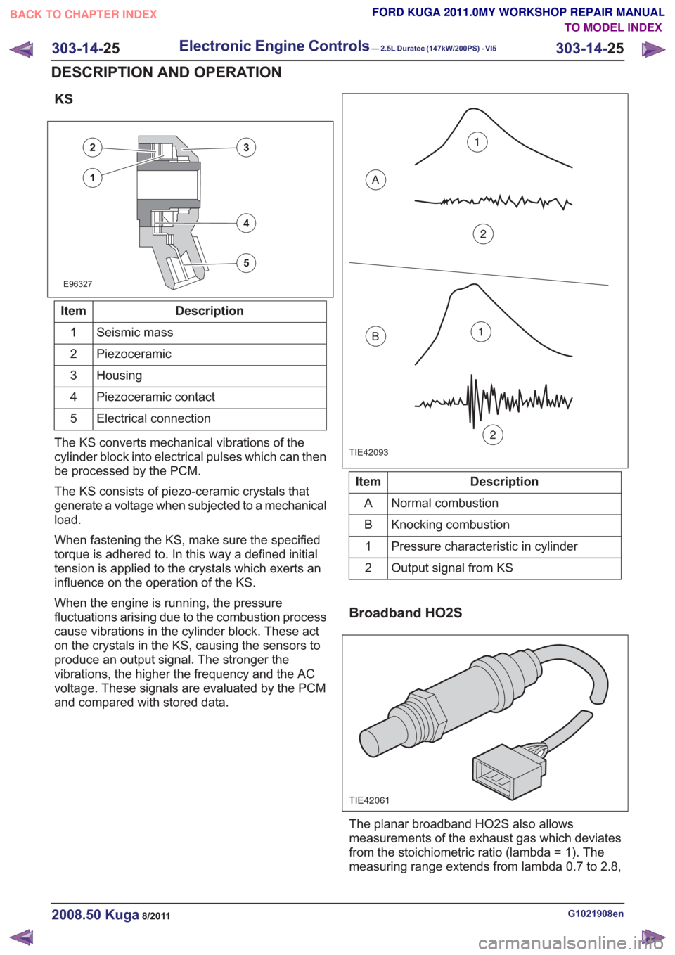
KS
E96327
23
5
4
1
Description
Item
Seismic mass
1
Piezoceramic
2
Housing
3
Piezoceramic contact
4
Electrical connection
5
The KS converts mechanical vibrations of the
cylinder block into electrical pulses which can then
be processed by the PCM.
The KS consists of piezo-ceramic crystals that
generate a voltage when subjected to a mechanical
load.
When fastening the KS, make sure the specified
torque is adhered to. In this way a defined initial
tension is applied to the crystals which exerts an
influence on the operation of the KS.
When the engine is running, the pressure
fluctuations arising due to the combustion process
cause vibrations in the cylinder block. These act
on the crystals in the KS, causing the sensors to
produce an output signal. The stronger the
vibrations, the higher the frequency and the AC
voltage. These signals are evaluated by the PCM
and compared with stored data.
TIE42093
1
2
A
B1
2
Description
Item
Normal combustion
A
Knocking combustion
B
Pressure characteristic in cylinder
1
Output signal from KS
2
Broadband HO2S
TIE42061
The planar broadband HO2S also allows
measurements of the exhaust gas which deviates
from the stoichiometric ratio (lambda = 1). The
measuring range extends from lambda 0.7 to 2.8,
G1021908en2008.50 Kuga8/2011
303-14- 25
Electronic Engine Controls— 2.5L Duratec (147kW/200PS) - VI5303-14-
25
DESCRIPTION AND OPERATION
TO MODEL INDEX
BACK TO CHAPTER INDEX
FORD KUGA 2011.0MY WORKSHOP REPAIR MANUAL
Page 1802 of 2057
voltage signal to the PCM corresponding to the
aspirated air mass.
This analogue voltage signal is between 0.5V and
5V. Low mass of intake air produces a low voltage
signal. A high mass of intake air produces a
correspondingly high voltage signal.
The MAF sensor is also capable of detecting the
backflow of the intake air. A sensor element is
heated electrically on the integrated chip and then
cooled by the air flowing through. The regulating
switch supplies the heating current in such a way
that it attains a constant excess temperature in
comparison to the intake air. The mass air flow and
the direction of flow can be derived from this
heating current (given in the form of a signal
voltage). Below a certain voltage value there is a
return flow. The direction is flow is registered by
two sensors pointing in different directions. The
measurement does not require a great deal of
software processing effort, even with a strongly
pulsating mass air flow.MAPT
E96146
The MAPT sensor combines two sensors in one
housing. These are the MAP sensor and the IAT
sensor. They take the form of a piezoelectric
resistor and an NTC resistor.
The MAP sensor receives a reference voltage of
5V from the PCM. The output signal from the MAP
sensor element is an analog voltage signal which
changes proportionately to the prevailing pressure
in the intake manifold.
The IAT sensor records the temperature of the
intake air downstream of the intercooler.
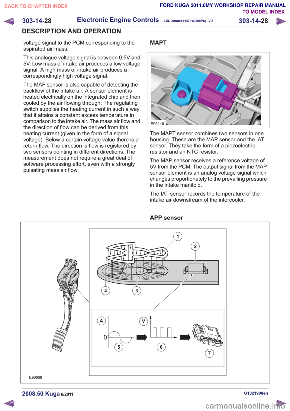
APP sensor
00
E96668
1
2
43
AV
56
7
G1021908en2008.50 Kuga8/2011
303-14-28
Electronic Engine Controls— 2.5L Duratec (147kW/200PS) - VI5303-14-
28
DESCRIPTION AND OPERATION
TO MODEL INDEX
BACK TO CHAPTER INDEX
FORD KUGA 2011.0MY WORKSHOP REPAIR MANUAL
Page 1804 of 2057
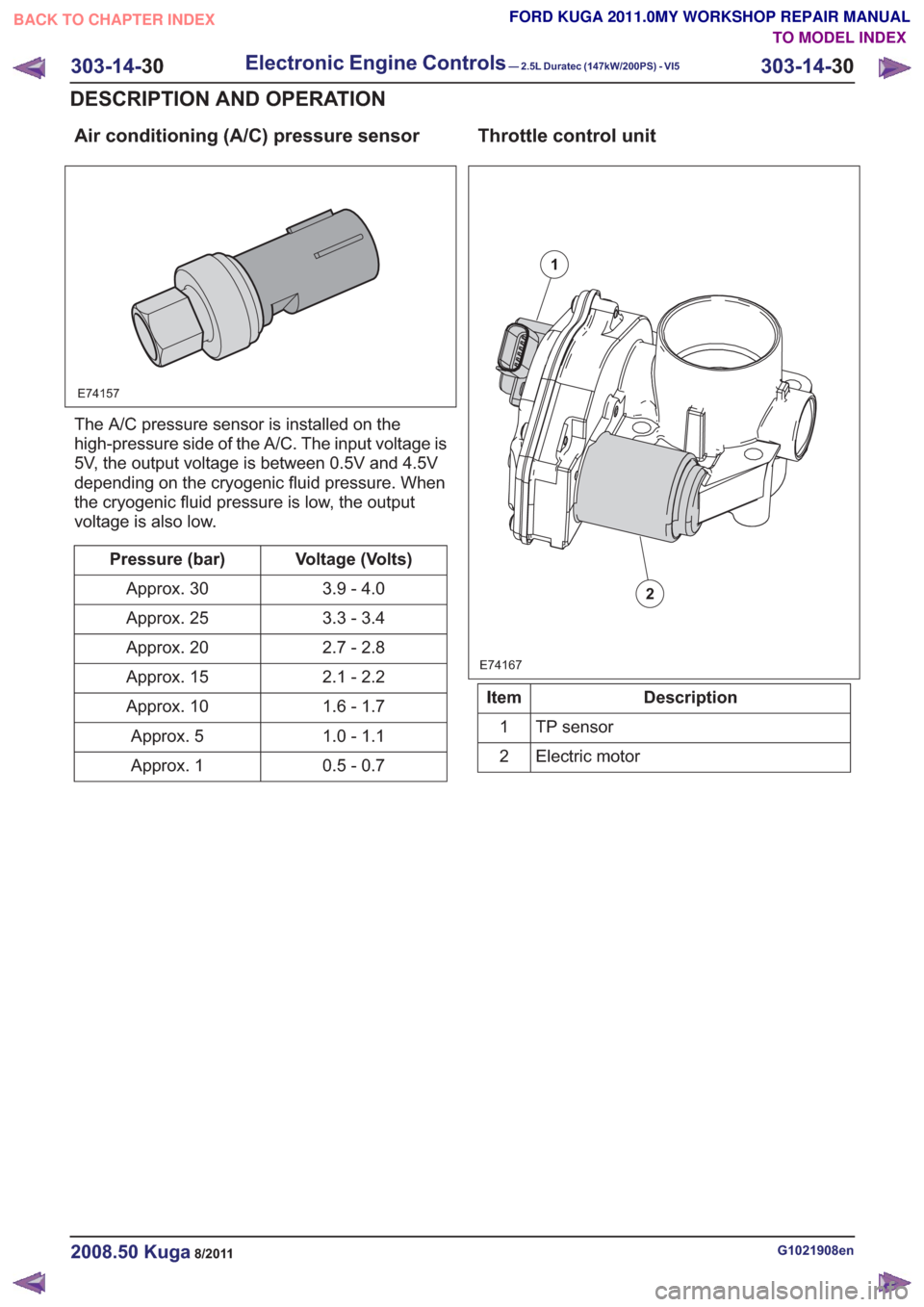
Air conditioning (A/C) pressure sensor
E74157
The A/C pressure sensor is installed on the
high-pressure side of the A/C. The input voltage is
5V, the output voltage is between 0.5V and 4.5V
depending on the cryogenic fluid pressure. When
the cryogenic fluid pressure is low, the output
voltage is also low.
Voltage (Volts)
Pressure (bar)
3.9 - 4.0
Approx. 30
3.3 - 3.4
Approx. 25
2.7 - 2.8
Approx. 20
2.1 - 2.2
Approx. 15
1.6 - 1.7
Approx. 10
1.0 - 1.1
Approx. 5
0.5 - 0.7
Approx. 1
Throttle control unit
E74167
1
2
Description
Item
TP sensor
1
Electric motor
2
G1021908en2008.50 Kuga8/2011
303-14- 30
Electronic Engine Controls— 2.5L Duratec (147kW/200PS) - VI5303-14-
30
DESCRIPTION AND OPERATION
TO MODEL INDEX
BACK TO CHAPTER INDEX
FORD KUGA 2011.0MY WORKSHOP REPAIR MANUAL
Page 1807 of 2057
Description
Item
Coil-on-plug ignition coil
1
Spark plug connector
2
Low-voltage connection
3
Laminated soft-iron core
4Description
Item
Primary winding
5
Secondary winding
6
Spark plug
7
High-voltage connection via spring contact
8
In an ignition system with coil-on-plug ignition coils,
each cylinder is actuated individually and only once
per cycle (working stroke). The coil-on-plug ignition
coils are mounted directly on the spark plugs,
therefore no ignition cables are required between
the ignition coils and the spark plugs.
Each individual ignition coil is actuated on the
low-voltage side by the PCM. The power
end-stages are incorporated into the coil-on-plug
ignition coils. Only the actuating current for these
power end-stages is controlled by the PCM.
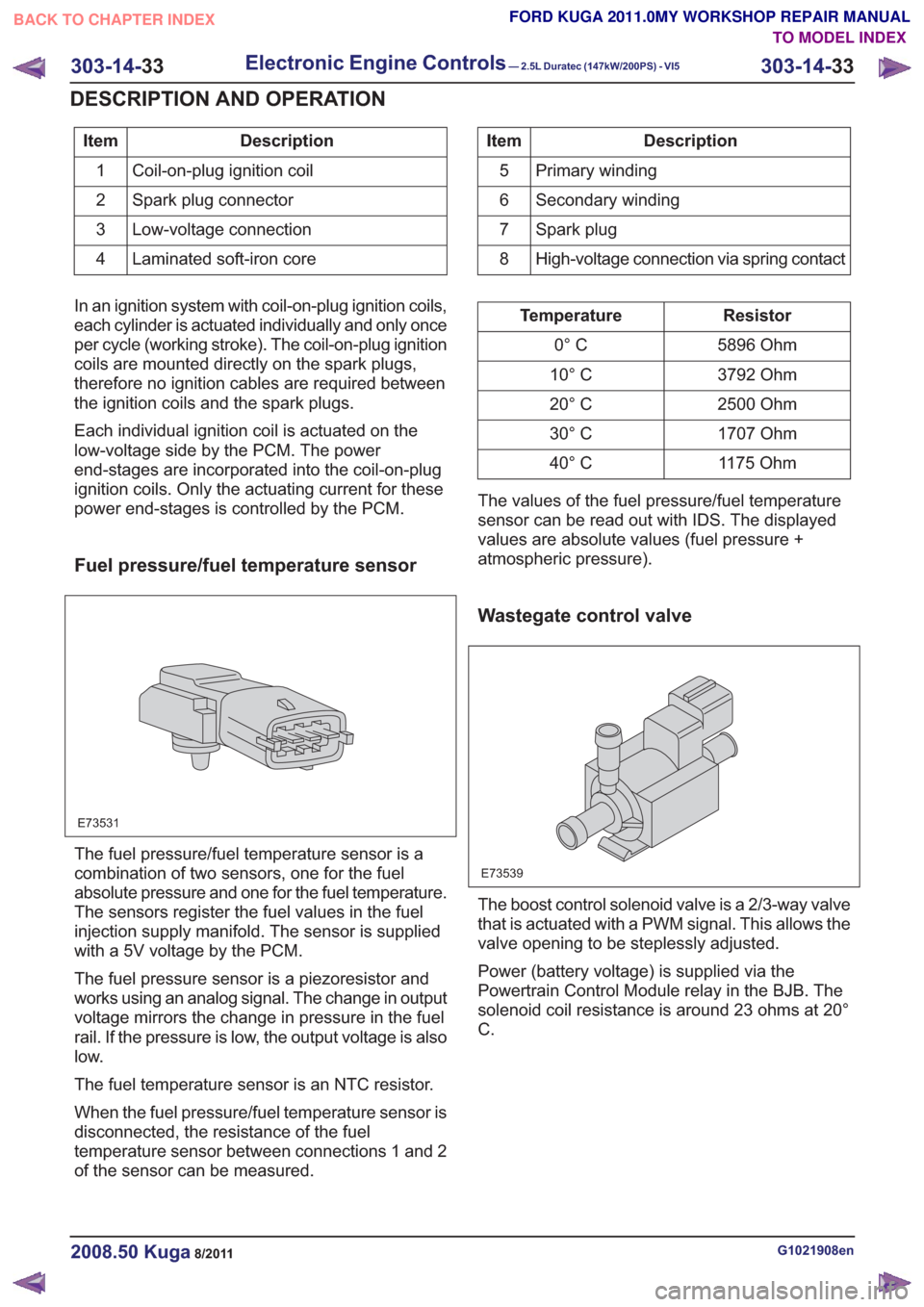
Fuel pressure/fuel temperature sensor
E73531
The fuel pressure/fuel temperature sensor is a
combination of two sensors, one for the fuel
absolute pressure and one for the fuel temperature.
The sensors register the fuel values in the fuel
injection supply manifold. The sensor is supplied
with a 5V voltage by the PCM.
The fuel pressure sensor is a piezoresistor and
works using an analog signal. The change in output
voltage mirrors the change in pressure in the fuel
rail. If the pressure is low, the output voltage is also
low.
The fuel temperature sensor is an NTC resistor.
When the fuel pressure/fuel temperature sensor is
disconnected, the resistance of the fuel
temperature sensor between connections 1 and 2
of the sensor can be measured.
Resistor
Temperature
5896 Ohm
0° C
3792 Ohm
10° C
2500 Ohm
20° C
1707 Ohm
30° C
1175 Ohm
40° C
The values of the fuel pressure/fuel temperature
sensor can be read out with IDS. The displayed
values are absolute values (fuel pressure +
atmospheric pressure).
Wastegate control valve
E73539
The boost control solenoid valve is a 2/3-way valve
that is actuated with a PWM signal. This allows the
valve opening to be steplessly adjusted.
Power (battery voltage) is supplied via the
Powertrain Control Module relay in the BJB. The
solenoid coil resistance is around 23 ohms at 20°
C.
G1021908en2008.50 Kuga8/2011
303-14- 33
Electronic Engine Controls— 2.5L Duratec (147kW/200PS) - VI5303-14-
33
DESCRIPTION AND OPERATION
TO MODEL INDEX
BACK TO CHAPTER INDEX
FORD KUGA 2011.0MY WORKSHOP REPAIR MANUAL
Page 1850 of 2057
To exactly determine the activation points of the
gear shifts and torque converter lockup on the
basis of the type of driving mode chosen, the TCM
receives the following information:
• Selected transmission range (TR sensor)
• Selected driving mode (normal/sport/select-shift)
• Transmission input shaft speed (TSS sensor)
• Transmission output shaft speed (OSS sensor)
• Transmission fluid temperature (TFT sensor)
• The engine speed and the torque as well as thethrottle plate opening - from the PCM via the
CAN databus
• Actuation of accelerator – from the PCM via the CAN databus
• The coolant temperature – from the PCM via the CAN databus
• Road speed – from the ABS module via the CAN databus
• Actuation of brake pedal – from the PCM via the CAN databus
Gearshift control
Adaptation
The TCM monitors every shift operation in all
driving conditions to make even and smooth gear
shifts possible. This is done by the control module,
which either lowers or increases the hydraulic line
pressure during gearshifts.
The changed pressure values are stored in the
control module memory after the engine is switched
off and retrieved during engine starting. This
improves the shift comfort and extends the service
life.
Full adaptability occurs when the following criteria
are met:
• Throttle plate opening is constant.
• Transmission fluid temperature between 65 °Cand 110 °C.
Shifting from 'P' to another transmission
range
To be able to move the selector lever from 'P' into
another transmission range, the ignition must be
switched on and the brake pedal pressed (stoplamp
switch on). The TCM detects the position of the
brake pedal via the CAN data bus and the engaged
transmission range from the TR sensor. Based on this information, the TCM transmits a
signal to the select-shift switch module. This
activates the brake shift interlock actuator in the
selector lever assembly.
When the brake shift interlock actuator is activated,
the locking pin is retracted so that another
transmission range can be selected.
The brake shift interlock actuator is deactivated
when the ignition is switched off. It is mechanically
locked when the gear selector lever is in 'P'.
Automatic transmission, selector lever in
position "D".
The TCM adapts the shift points to match the
driving conditions. Normally the TCM is in adaptive
mode and gear changes take place adapted to the
driving conditions. If special driving conditions are
detected, the TCM switches to predefined
characteristics.
When driving with normal acceleration, the TCM
uses a preset shift program which is optimized for
economical driving.
This shift program is suitable for "normal" driving
and delivers early upward changes and torque
converter lockup. Furthermore, the transmission
fluid pressure is adapted to make smooth
engagement of the gears possible.
Sport mode, selector lever in position "S"
The transmission switches from automatic
operation into sport mode. In this mode the TCM
switches to another set of characteristic curves.
These characteristic curves for control of the gear
changes are adapted to sporting calculations (e.g.
gear change at higher engine speed).
In the sport mode shift program the shift points are
set so that good performance is offered. Changing
down occurs at lower engine speeds.
Manual gear changes (select-shift mode) can be
made in sport mode by moving the selector lever
in the (+) or (-) direction.
Changing gear in select-shift mode
If you move the selector lever to 'S', the automatic
transaxle remains hydraulically in 'D' position. If
you move the gear selector lever forwards (-), the
G1163605en2008.50 Kuga8/2011
307-01-
29
Automatic Transmission/Transaxle
— Vehicles With:
5-Speed Automatic Transaxle - AW55 AWD
307-01- 29
DESCRIPTION AND OPERATION
TO MODEL INDEX
BACK TO CHAPTER INDEX
FORD KUGA 2011.0MY WORKSHOP REPAIR MANUAL
Page 1872 of 2057
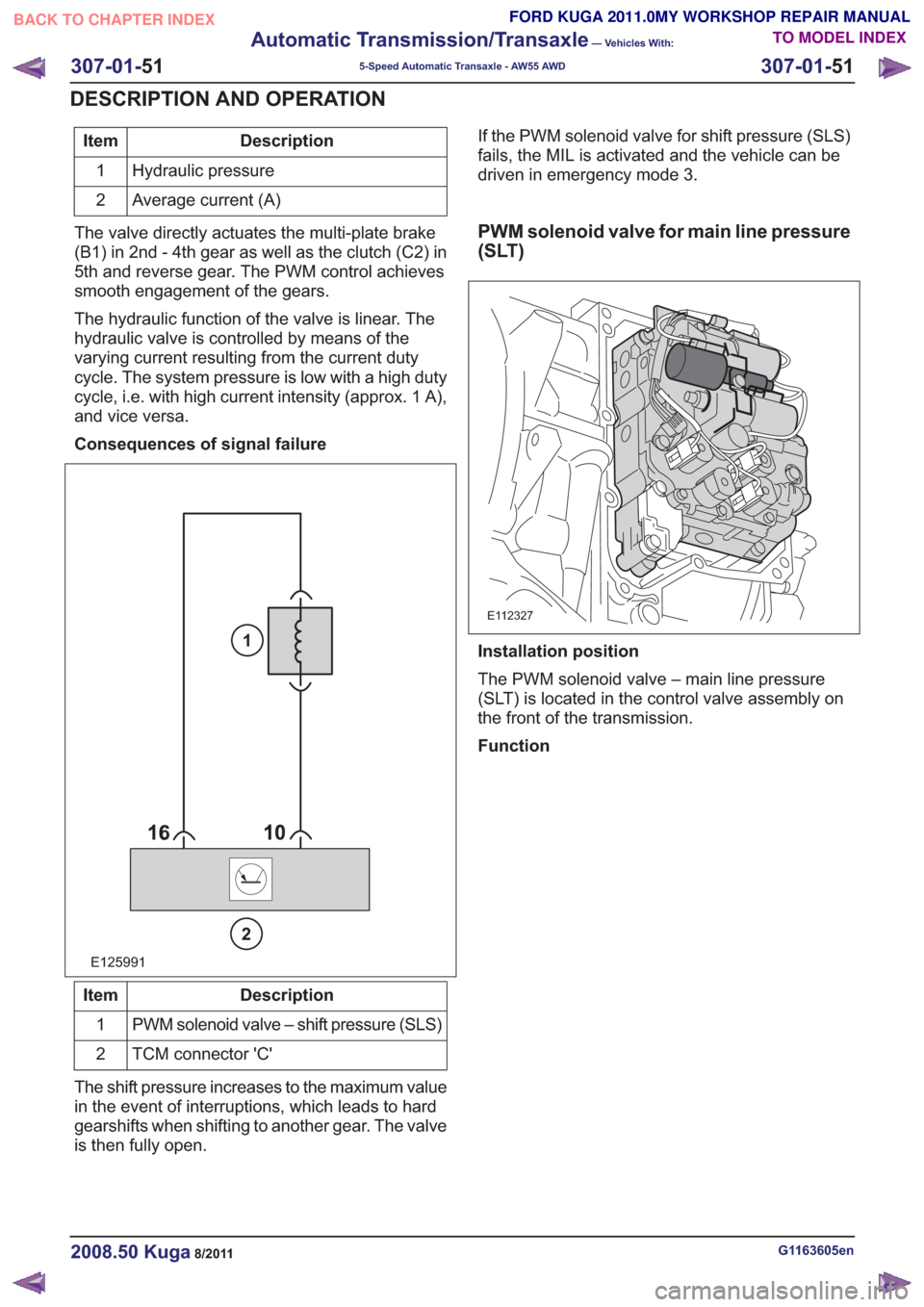
Description
Item
Hydraulic pressure
1
Average current (A)
2
The valve directly actuates the multi-plate brake
(B1) in 2nd - 4th gear as well as the clutch (C2) in
5th and reverse gear. The PWM control achieves
smooth engagement of the gears.
The hydraulic function of the valve is linear. The
hydraulic valve is controlled by means of the
varying current resulting from the current duty
cycle. The system pressure is low with a high duty
cycle, i.e. with high current intensity (approx. 1 A),
and vice versa.
Consequences of signal failure
E125991
2
1
Description
Item
PWM solenoid valve – shift pressure (SLS)
1
TCM connector 'C'
2
The shift pressure increases to the maximum value
in the event of interruptions, which leads to hard
gearshifts when shifting to another gear. The valve
is then fully open. If the PWM solenoid valve for shift pressure (SLS)
fails, the MIL is activated and the vehicle can be
driven in emergency mode 3.
PWM solenoid valve for main line pressure
(SLT)
E112327
Installation position
The PWM solenoid valve – main line pressure
(SLT) is located in the control valve assembly on
the front of the transmission.
Function
G1163605en2008.50 Kuga8/2011
307-01-
51
Automatic Transmission/Transaxle
— Vehicles With:
5-Speed Automatic Transaxle - AW55 AWD
307-01- 51
DESCRIPTION AND OPERATION
TO MODEL INDEX
BACK TO CHAPTER INDEX
FORD KUGA 2011.0MY WORKSHOP REPAIR MANUAL
Page 2018 of 2057
Air Conditioning (A/C) System Recovery, Evacuation and Charging
General EquipmentAir Conditioning Service Unit
Automatic Calibration Halogen Leak Detector
Electronic Leak Detector
Refrigerant Identification Equipment
UV Leak Detector
1. Refer to: Air Conditioning (A/C) System Health
and Safety Precautions (100-00 General
Information, Description and Operation).
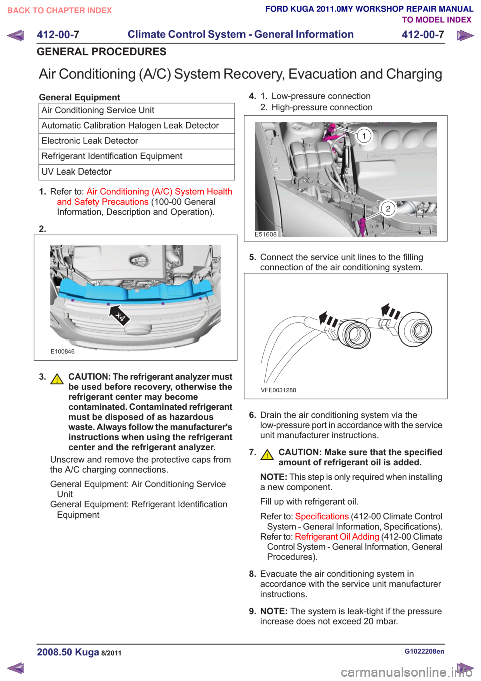
2.
E100846
x4
3. CAUTION: The refrigerant analyzer must be used before recovery, otherwise the
refrigerant center may become
contaminated. Contaminated refrigerant
must be disposed of as hazardous
waste. Always follow the manufacturer's
instructions when using the refrigerant
center and the refrigerant analyzer.
Unscrew and remove the protective caps from
the A/C charging connections.
General Equipment: Air Conditioning Service Unit
General Equipment: Refrigerant Identification Equipment 4.
Low-pressure connection
1.
2. High-pressure connection
2
E51608
1
5. Connect the service unit lines to the filling
connection of the air conditioning system.
VFE0031288
6.Drain the air conditioning system via the
low-pressure port in accordance with the service
unit manufacturer instructions.
7. CAUTION: Make sure that the specified amount of refrigerant oil is added.
NOTE:This step is only required when installing
a new component.
Fill up with refrigerant oil.
Refer to: Specifications (412-00 Climate Control
System - General Information, Specifications).
Refer to: Refrigerant Oil Adding (412-00 Climate
Control System - General Information, General
Procedures).
8. Evacuate the air conditioning system in
accordance with the service unit manufacturer
instructions.
9. NOTE: The system is leak-tight if the pressure
increase does not exceed 20 mbar.
G1022208en2008.50 Kuga8/2011
412-00- 7
Climate Control System - General Information
412-00- 7
GENERAL PROCEDURES
TO MODEL INDEX
BACK TO CHAPTER INDEX
FORD KUGA 2011.0MY WORKSHOP REPAIR MANUAL
Page 2019 of 2057
Perform the leak test, by closing the hand valves
on the gauge set, switching off the service unit
vacuum pump and observing the low pressure
gauge.
10. N O T E : This step is only necessary if the
pressure increase exceeds 20 mbar.
Locate and rectify any leaks in the A/C
refrigerant circuit using a leak tester.
General Equipment: UV Leak Detector
General Equipment: Electronic Leak Detector
General Equipment: Automatic Calibration Halogen Leak Detector
11 . Add refrigerant oil to the air conditioning system.
Refer to: Specifications (412-00 Climate Control
System - General Information, Specifications).
Refer to: Refrigerant Oil Adding (412-00 Climate
Control System - General Information, General
Procedures).
12. Fill the air conditioning system with liquid
through the high-pressure connection.
Refer to: Specifications (412-00 Climate Control
System - General Information, Specifications).
13. Open the shut-off valve on the high-pressure
side.
1.
2. Switch the service unit to "Fill" mode and fill
the system with the specified quantity of
liquid refrigerant (R134a).
14. Fill the air conditioning system with gas through
the low-pressure connection.
Refer to: Specifications (412-00 Climate Control
System - General Information, Specifications).
15. Open the shut-off valve on the low-pressure
side.
1.
2. Switch the service unit to "Fill" mode and fill
the system with the specified quantity of
gaseous refrigerant.
3. Add the remaining amount of refrigerant with the air conditioning switched on. To do so
run the engine at about 1200-1500 rev/min.
Set the air conditioning system to full cooling
power and fresh air mode. Set the blower
motor to the highest setting. Fill with the
remainder of the specified fill capacity.
16. Disconnect the service unit. 17.
Close the shut-off valve.
1.
2. Switch off the service unit.
3. Disconnect the service unit lines from the
filling connections of the air conditioning
system.
4. Screw the protective caps onto the charging connections.
18. Install all components in reverse order.
G1022208en2008.50 Kuga8/2011
412-00- 8
Climate Control System - General Information
412-00- 8
GENERAL PROCEDURES
TO MODEL INDEX
BACK TO CHAPTER INDEX
FORD KUGA 2011.0MY WORKSHOP REPAIR MANUAL