Page 1546 of 2057
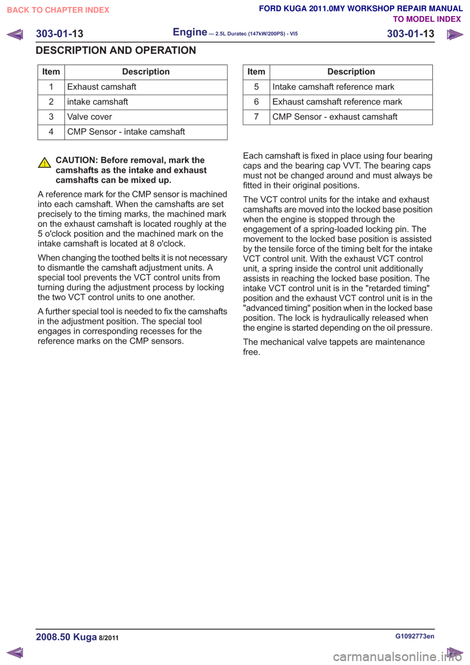
Description
Item
Exhaust camshaft
1
intake camshaft
2
Valve cover
3
CMP Sensor - intake camshaft
4Description
Item
Intake camshaft reference mark
5
Exhaust camshaft reference mark
6
CMP Sensor - exhaust camshaft
7
CAUTION: Before removal, mark the
camshafts as the intake and exhaust
camshafts can be mixed up.
A reference mark for the CMP sensor is machined
into each camshaft. When the camshafts are set
precisely to the timing marks, the machined mark
on the exhaust camshaft is located roughly at the
5 o'clock position and the machined mark on the
intake camshaft is located at 8 o'clock.
When changing the toothed belts it is not necessary
to dismantle the camshaft adjustment units. A
special tool prevents the VCT control units from
turning during the adjustment process by locking
the two VCT control units to one another.
A further special tool is needed to fix the camshafts
in the adjustment position. The special tool
engages in corresponding recesses for the
reference marks on the CMP sensors. Each camshaft is fixed in place using four bearing
caps and the bearing cap VVT. The bearing caps
must not be changed around and must always be
fitted in their original positions.
The VCT control units for the intake and exhaust
camshafts are moved into the locked base position
when the engine is stopped through the
engagement of a spring-loaded locking pin. The
movement to the locked base position is assisted
by the tensile force of the timing belt for the intake
VCT control unit. With the exhaust VCT control
unit, a spring inside the control unit additionally
assists in reaching the locked base position. The
intake VCT control unit is in the "retarded timing"
position and the exhaust VCT control unit is in the
"advanced timing" position when in the locked base
position. The lock is hydraulically released when
the engine is started depending on the oil pressure.
The mechanical valve tappets are maintenance
free.
G1092773en2008.50 Kuga8/2011
303-01-
13
Engine— 2.5L Duratec (147kW/200PS) - VI5303-01-
13
DESCRIPTION AND OPERATION
TO MODEL INDEX
BACK TO CHAPTER INDEX
FORD KUGA 2011.0MY WORKSHOP REPAIR MANUAL
Page 1551 of 2057
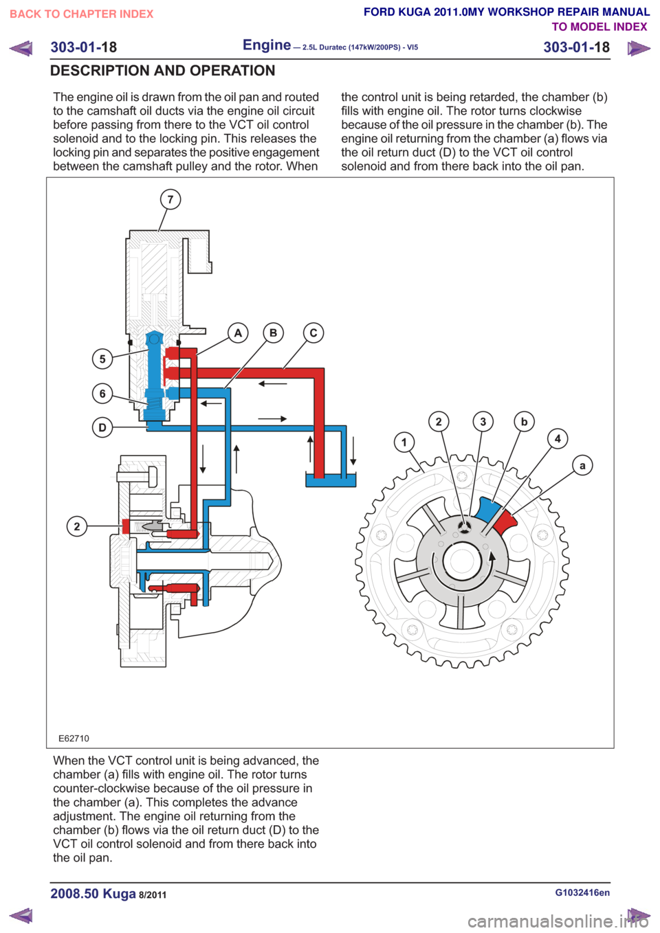
The engine oil is drawn from the oil pan and routed
to the camshaft oil ducts via the engine oil circuit
before passing from there to the VCT oil control
solenoid and to the locking pin. This releases the
locking pin and separates the positive engagement
between the camshaft pulley and the rotor. Whenthe control unit is being retarded, the chamber (b)
fills with engine oil. The rotor turns clockwise
because of the oil pressure in the chamber (b). The
engine oil returning from the chamber (a) flows via
the oil return duct (D) to the VCT oil control
solenoid and from there back into the oil pan.
E62710
When the VCT control unit is being advanced, the
chamber (a) fills with engine oil. The rotor turns
counter-clockwise because of the oil pressure in
the chamber (a). This completes the advance
adjustment. The engine oil returning from the
chamber (b) flows via the oil return duct (D) to the
VCT oil control solenoid and from there back into
the oil pan.
G1032416en2008.50 Kuga8/2011
303-01-
18
Engine— 2.5L Duratec (147kW/200PS) - VI5303-01-
18
DESCRIPTION AND OPERATION
TO MODEL INDEX
BACK TO CHAPTER INDEX
FORD KUGA 2011.0MY WORKSHOP REPAIR MANUAL
Page 1582 of 2057
Exhaust Manifold(21 187 0)
Removal
1.Refer to: Turbocharger (303-04 Fuel Charging
and Controls - Turbocharger - 2.5L Duratec
(147kW/200PS) - VI5, Removal and
Installation).
Installation
1. Refer to: Turbocharger (303-04 Fuel Charging
and Controls - Turbocharger - 2.5L Duratec
(147kW/200PS) - VI5, Removal and
Installation).
G1079021en2008.50 Kuga8/2011
303-01- 49
Engine— 2.5L Duratec (147kW/200PS) - VI5303-01-
49
REMOVAL AND INSTALLATION
TO MODEL INDEX
BACK TO CHAPTER INDEX
FORD KUGA 2011.0MY WORKSHOP REPAIR MANUAL
Page 1659 of 2057
26.Torque: 48Nm1.
2. Torque: 9
Nm
E114610
27.Torque: 25
E114609
28.
E114728
29.Torque: 25Nm
E114606
30. CAUTION: Gearshift cables must not be
kinked or bent.
Refer to: Selector Lever Cable Adjustment -
Vehicles With: 5-Speed Automatic Transaxle
- AW55 AWD (307-05 Automatic
Transmission/Transaxle External Controls -
Vehicles With: 5-Speed Automatic Transaxle
- AW55 AWD/6-Speed Automatic Transaxle
- 6DCT450, General Procedures).
G1191241en2008.50 Kuga8/2011
303-01- 126
Engine— 2.5L Duratec (147kW/200PS) - VI5303-01-
126
INSTALLATION
TO MODEL INDEX
BACK TO CHAPTER INDEX
FORD KUGA 2011.0MY WORKSHOP REPAIR MANUAL
1
1
2
Nm
E114436
x2
Page 1674 of 2057
Engine Cooling — 2.5L Duratec (147kW/200PS) - VI5 – Overview
Auxiliary coolant pump
An electrically operated auxiliary coolant pump is
installed on vehicles with a trailer coupling and/or
additional heating. The auxiliary coolant pump
ensures that the coolant is circulated when the
coolant pump (which is driven by the engine) is not
running.
The additional heating uses the auxiliary coolant
pump to circulate hot coolant through the heat
exchanger and the engine.
On vehicles with a trailer coupling the auxiliary
coolant pump is switched on for 6 minutes by the
PCM (powertrain control module) if the coolant
temperature exceeds 106°C when the engine is
switched off. This prevents the coolant circuit from
overheating. This could happen particularly if the
engine is switched off after towing a heavy trailer
up a steep hill before there has been sufficient time
for cooling.
G1088220en2008.50 Kuga8/2011
303-03-3
Engine Cooling
303-03- 3
DESCRIPTION AND OPERATION
TO MODEL INDEX
BACK TO CHAPTER INDEX
FORD KUGA 2011.0MY WORKSHOP REPAIR MANUAL
Page 1675 of 2057
Engine Cooling
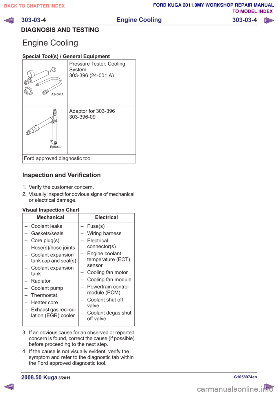
Special Tool(s) / General EquipmentPressure Tester, Cooling
System
303-396 (24-001 A)
IA24001A
Adaptor for 303-396
303-396-09
E55030
Ford approved diagnostic tool
Inspection and Verification
1. Verify the customer concern.
2. Visually inspect for obvious signs of mechanicalor electrical damage.
Visual Inspection Chart
Electrical
Mechanical
– Fuse(s)
– Wiring harness
– Electricalconnector(s)
– Engine coolant temperature (ECT)
sensor
– Cooling fan motor
– Cooling fan module
– Powertrain control module (PCM)
– Coolant shut off valve
– Coolant degas shut off valve
– Coolant leaks
– Gaskets/seals
– Core plug(s)
– Hose(s)/hose joints
– Coolant expansion
tank cap and seal(s)
– Coolant expansion tank
– Radiator
– Coolant pump
– Thermostat
– Heater core
– Exhaust gas recircu- lation (EGR) cooler
3. If an obvious cause for an observed or reported concern is found, correct the cause (if possible)
before proceeding to the next step.
4. If the cause is not visually evident, verify the symptom and refer to the diagnostic tab within
the Ford approved diagnostic tool.
G1058974en2008.50 Kuga8/2011
303-03- 4
Engine Cooling
303-03- 4
DIAGNOSIS AND TESTING
TO MODEL INDEX
BACK TO CHAPTER INDEX
FORD KUGA 2011.0MY WORKSHOP REPAIR MANUAL
Page 1695 of 2057
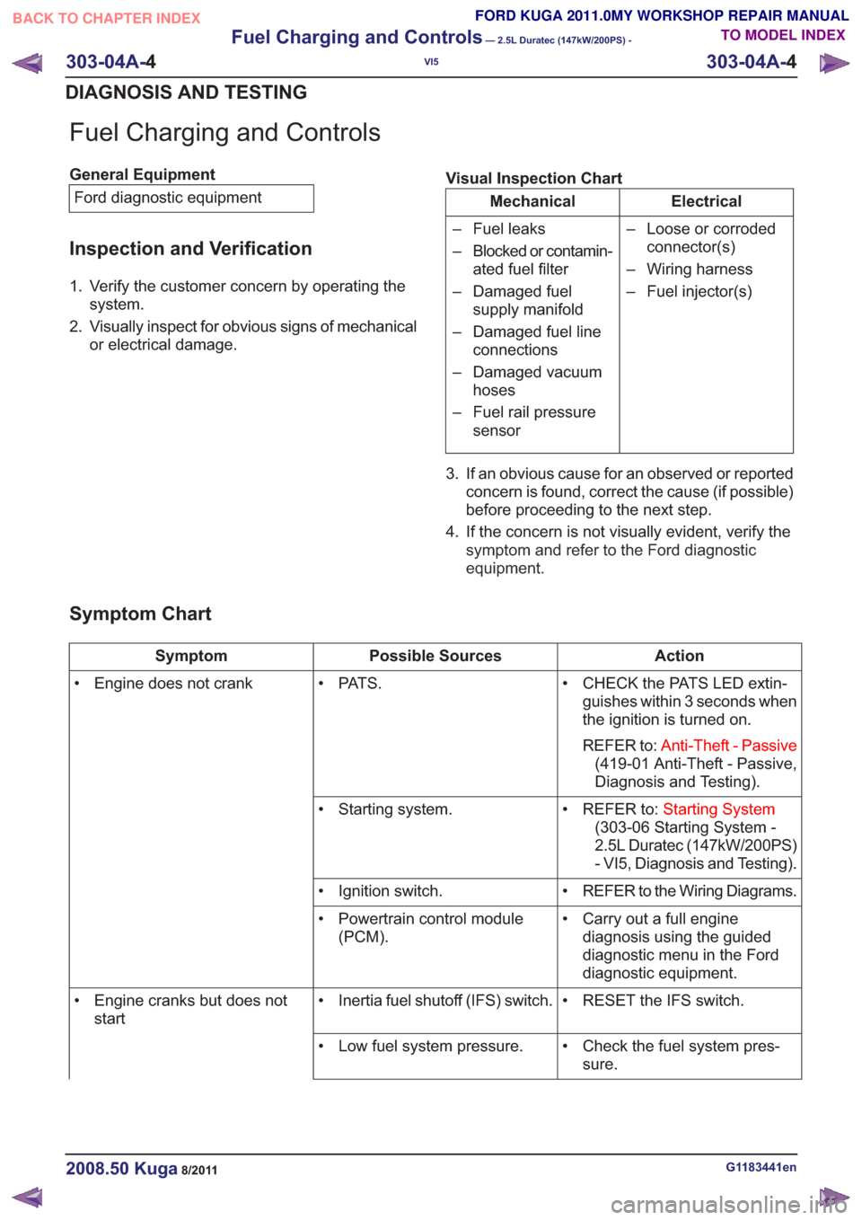
Fuel Charging and Controls
General EquipmentFord diagnostic equipment
Inspection and Verification
1. Verify the customer concern by operating the system.
2. Visually inspect for obvious signs of mechanical or electrical damage. Visual Inspection Chart
Electrical
Mechanical
– Loose or corrodedconnector(s)
– Wiring harness
– Fuel injector(s)
– Fuel leaks
– Blocked or contamin-
ated fuel filter
– Damaged fuel supply manifold
– Damaged fuel line connections
– Damaged vacuum hoses
– Fuel rail pressure sensor
3. If an obvious cause for an observed or reported concern is found, correct the cause (if possible)
before proceeding to the next step.
4. If the concern is not visually evident, verify the symptom and refer to the Ford diagnostic
equipment .
Symptom Chart
Action
Possible Sources
Symptom
• CHECK the PATS LED extin-guishes within 3 seconds when
the ignition is turned on.
REFER to: Anti-Theft - Passive
(419-01 Anti-Theft - Passive,
Diagnosis and Testing).
• PAT S .
• Engine does not crank
• REFER to:Starting System
(303-06 Starting System -
2.5L Duratec (147kW/200PS)
- VI5, Diagnosis and Testing).
• Starting system.
• REFER to the Wiring Diagrams.
• Ignition switch.
• Carry out a full enginediagnosis using the guided
diagnostic menu in the Ford
diagnostic equipment.
• Powertrain control module
(PCM).
• RESET the IFS switch.
• Inertia fuel shutoff (IFS) switch.
• Engine cranks but does not
start
• Check the fuel system pres-sure.
• Low fuel system pressure.
G1183441en2008.50 Kuga8/2011
303-04A-
4
Fuel Charging and Controls
— 2.5L Duratec (147kW/200PS) -
VI5
303-04A- 4
DIAGNOSIS AND TESTING
TO MODEL INDEX
BACK TO CHAPTER INDEX
FORD KUGA 2011.0MY WORKSHOP REPAIR MANUAL
Page 1696 of 2057
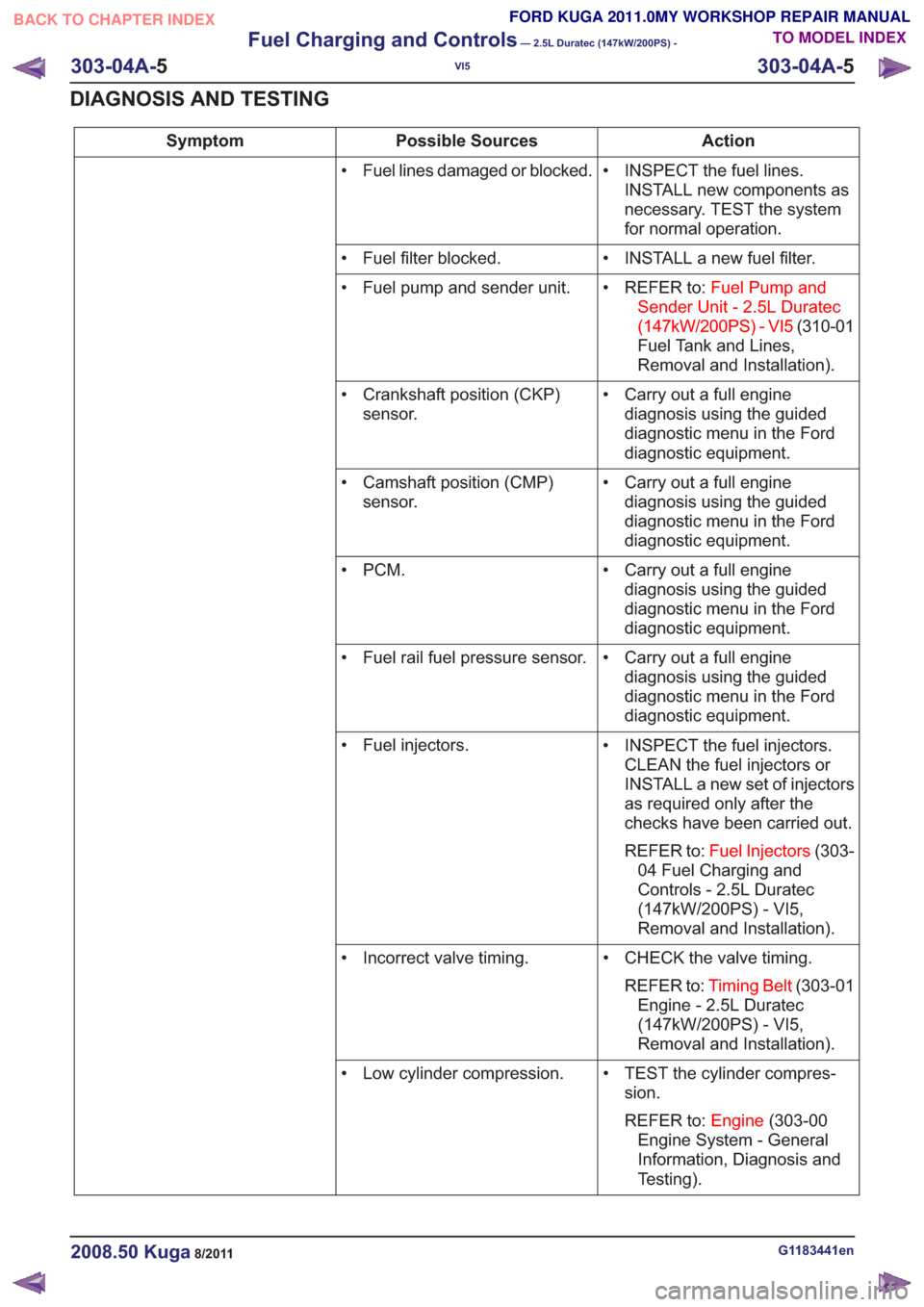
Action
Possible Sources
Symptom
• INSPECT the fuel lines.INSTALL new components as
necessary. TEST the system
for normal operation.
• Fuel lines damaged or blocked.
• INSTALL a new fuel filter.
• Fuel filter blocked.
• REFER to:Fuel Pump and
Sender Unit - 2.5L Duratec
(147kW/200PS) - VI5 (310-01
Fuel Tank and Lines,
Removal and Installation).
• Fuel pump and sender unit.
• Carry out a full enginediagnosis using the guided
diagnostic menu in the Ford
diagnostic equipment.
• Crankshaft position (CKP)
sensor.
• Carry out a full enginediagnosis using the guided
diagnostic menu in the Ford
diagnostic equipment.
• Camshaft position (CMP)
sensor.
• Carry out a full enginediagnosis using the guided
diagnostic menu in the Ford
diagnostic equipment.
•PCM.
• Carry out a full enginediagnosis using the guided
diagnostic menu in the Ford
diagnostic equipment.
• Fuel rail fuel pressure sensor.
• INSPECT the fuel injectors.CLEAN the fuel injectors or
INSTALL a new set of injectors
as required only after the
checks have been carried out.
REFER to: Fuel Injectors (303-
04 Fuel Charging and
Controls - 2.5L Duratec
(147kW/200PS) - VI5,
Removal and Installation).
• Fuel injectors.
• CHECK the valve timing.REFER to: Timing Belt (303-01
Engine - 2.5L Duratec
(147kW/200PS) - VI5,
Removal and Installation).
• Incorrect valve timing.
• TEST the cylinder compres-sion.
REFER to: Engine(303-00
Engine System - General
Information, Diagnosis and
Testing).
• Low cylinder compression.
G1183441en2008.50 Kuga8/2011
303-04A-
5
Fuel Charging and Controls
— 2.5L Duratec (147kW/200PS) -
VI5
303-04A- 5
DIAGNOSIS AND TESTING
TO MODEL INDEX
BACK TO CHAPTER INDEX
FORD KUGA 2011.0MY WORKSHOP REPAIR MANUAL