2011 FORD KUGA steering
[x] Cancel search: steeringPage 389 of 2057

Programmable Module Installation
Activation
5.
Install the most up-to-date software version in
IDS.
6. If, before replacing a module, it was not possible
to read out the vehicle-specific data using the
integrated diagnostic system (IDS) (the module
to be replaced does not respond) then, during
programming of the new module, the
vehicle-specific data must be entered manually
via a selection list in IDS or via a code which
can be obtained from the Technical Hotline.
7. In order to program, select the "Install
programmable module" submenu in the "Module
programming" menu tool box and then follow
the instructions.
8. The following modules must be programmed
after replacement:
•
• Anti-lock braking system module (ABS)
• Audio system module (ACM)
• CD player (CDP)
• Driver's door control unit (D-DCU)
• Passenger's door control unit (P-DCU)
• Rear left door control unit (RL-DCU)
• Rear right door control unit (RR-DCU)
• Electrical power steering (EPS)
• Generic Display Module (GDM) (vehicles
with DVD navigation system with
touchscreen)
• Generic electronic module (GEM)
• Headlamp control module (HCM) (vehicles with gas discharge headlamps)
• Instrument cluster (IC)
• Navigation system (NAV) (vehicles with navigation system)
• Parking aid module(PAM)
• Powertrain control module (PCM)
• Restraint control module (RCM)
• Rear entertainment system module (RETM) (vehicles with rear seat entertainment
system)
9. In order to configure the PCM, select the
"Programmable parameters" submenu in the
"Module programming" menu tool box and then
follow the instructions.
10. For vehicles with anti-lock braking system and
electronic stability program, these must also be configured using IDS following replacement of
the lateral acceleration sensor, yaw rate sensor
or pressure sensor. Configuration is performed
in the "Programmable parameters" menu tool
box.
G1158258en
2008.50 Kuga 8/2011 418-01-3
Module Configuration
418-01-3
GENERAL PROCEDURESTO MODEL INDEX
BACK TO CHAPTER INDEX
FORD KUGA 2011.0MY WORKSHOP REPAIR MANUAL
Page 446 of 2057

Anti-Theft - Passive – Overview
Programming the key
After exchanging the keyless vehicle module
(KVM), all available keys must be reprogrammed
using the Ford diagnostic unit. Both the passive
key and the emergency key must be
reprogrammed.
In addition, the KVM must be initialized with the
following modules using the Ford diagnostic unit:
• PCM
• Steering Lock Unit
If a new key has to be added, only this key must
be programmed using the Ford diagnostic unit.
If a key is to be deleted, all keys must first be
deleted and the remaining keys reprogrammed.
Up to 8 keys can be programmed.
Transceiver of passive anti-theft system
(emergency start function)
Between the emergency key holder and the
passive anti-theft system transceiver, there is a
copper ring that ensures the resonant frequency
of the transceiver. If this copper ring is not in the
correct position, the function of the emergency key
cannot be guaranteed.
G1065783en
2008.50 Kuga 8/2011 419-01B-3
Anti-Theft - Passive
419-01B-3
DESCRIPTION AND OPERATIONTO MODEL INDEX
BACK TO CHAPTER INDEX
FORD KUGA 2011.0MY WORKSHOP REPAIR MANUAL
Page 1158 of 2057
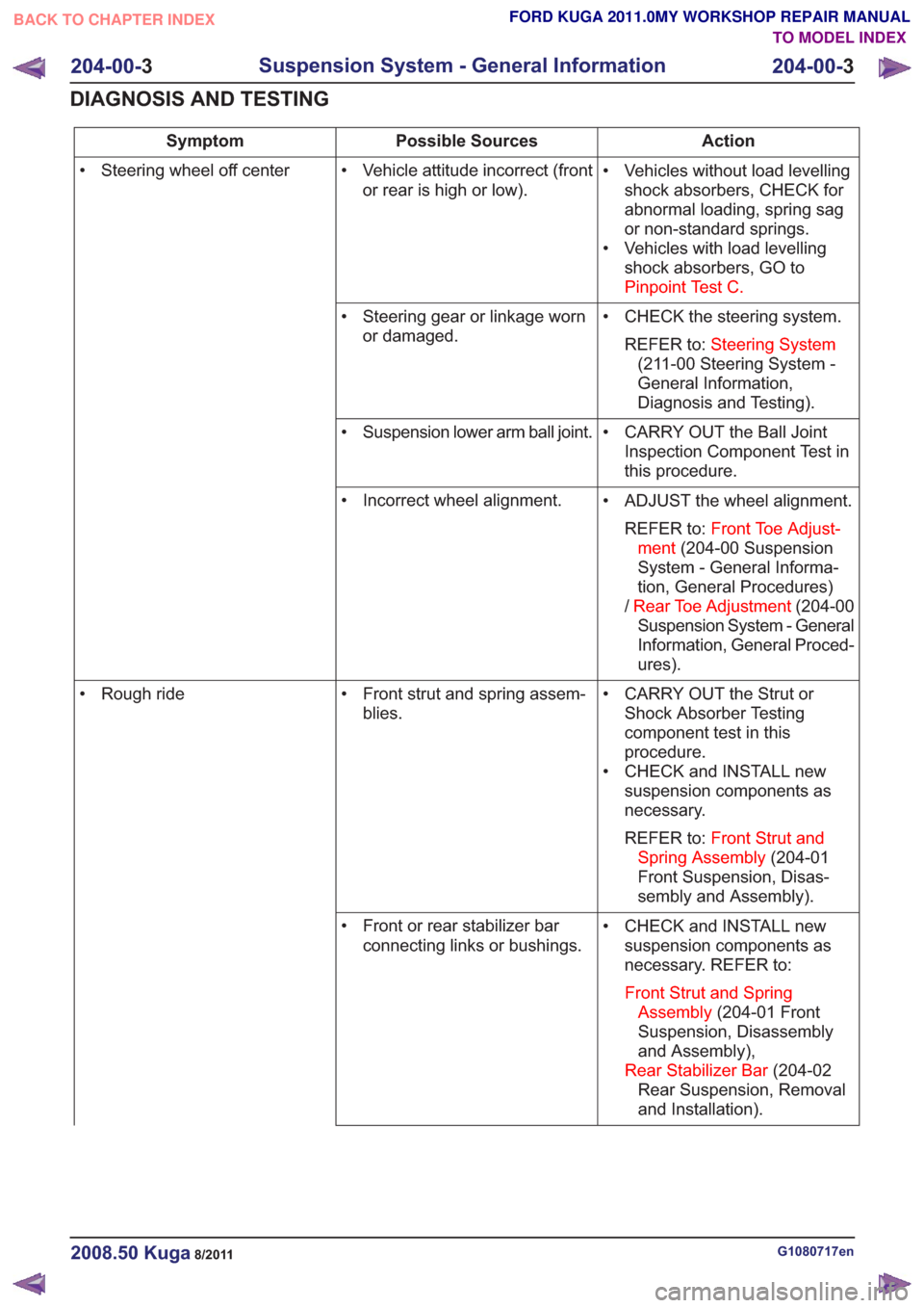
Action
Possible Sources
Symptom
• Vehicles without load levellingshock absorbers, CHECK for
abnormal loading, spring sag
or non-standard springs.
• Vehicles with load levelling shock absorbers, GO to
Pinpoint Test C.
• Vehicle attitude incorrect (front
or rear is high or low).
• Steering wheel off center
• CHECK the steering system.REFER to: Steering System
(211-00 Steering System -
General Information,
Diagnosis and Testing).
• Steering gear or linkage worn
or damaged.
• CARRY OUT the Ball JointInspection Component Test in
this procedure.
• Suspension lower arm ball joint.
• ADJUST the wheel alignment.REFER to: Front Toe Adjust-
ment (204-00 Suspension
System - General Informa-
tion, General Procedures)
/ Rear Toe Adjustment (204-00
Suspension System - General
Information, General Proced-
ures).
• Incorrect wheel alignment.
• CARRY OUT the Strut orShock Absorber Testing
component test in this
procedure.
• CHECK and INSTALL new suspension components as
necessary.
REFER to: Front Strut and
Spring Assembly (204-01
Front Suspension, Disas-
sembly and Assembly).
• Front strut and spring assem-
blies.
• Rough ride
• CHECK and INSTALL newsuspension components as
necessary. REFER to:
Front Strut and Spring Assembly (204-01 Front
Suspension, Disassembly
and Assembly),
Rear Stabilizer Bar (204-02
Rear Suspension, Removal
and Installation).
• Front or rear stabilizer bar
connecting links or bushings.
G1080717en2008.50 Kuga8/2011
204-00- 3
Suspension System - General Information
204-00- 3
DIAGNOSIS AND TESTING
TO MODEL INDEX
BACK TO CHAPTER INDEX
FORD KUGA 2011.0MY WORKSHOP REPAIR MANUAL
Page 1160 of 2057
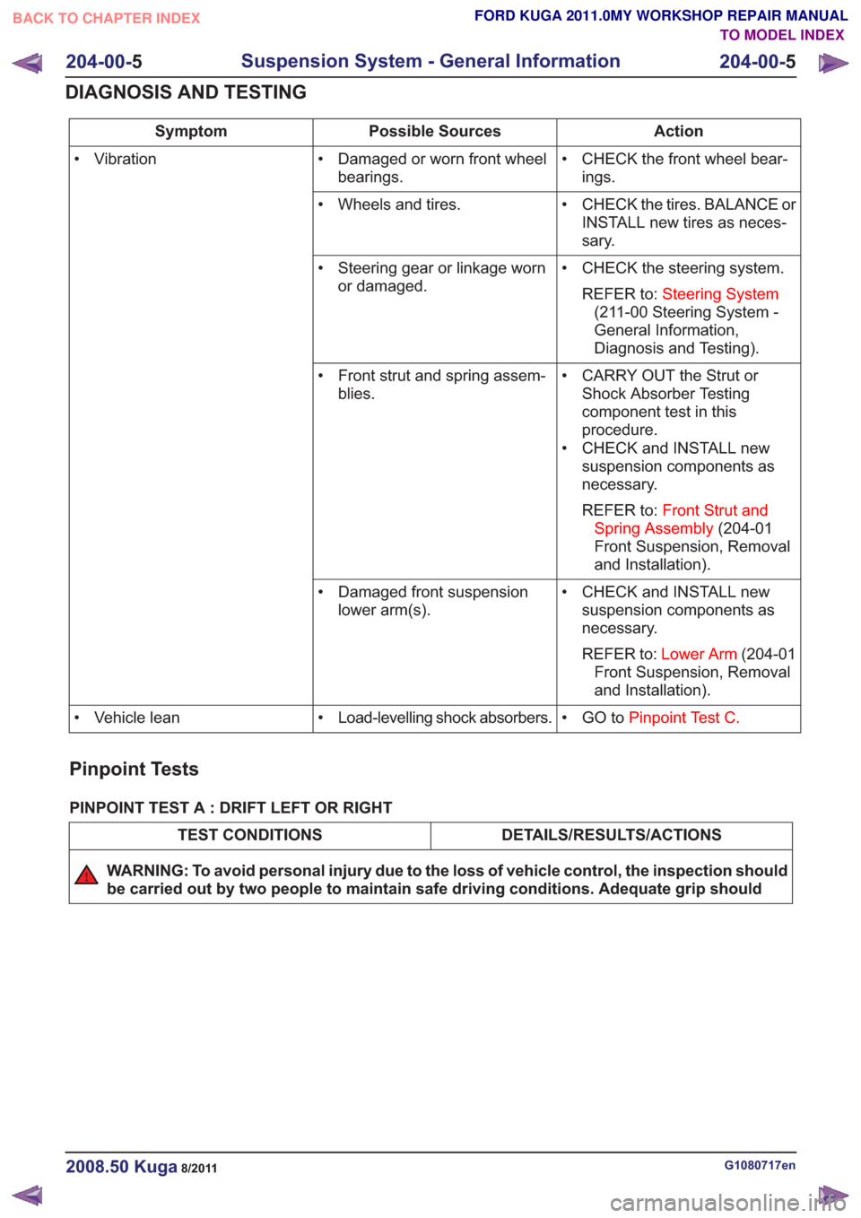
Action
Possible Sources
Symptom
• CHECK the front wheel bear-ings.
• Damaged or worn front wheel
bearings.
• Vibration
• CHECK the tires. BALANCE orINSTALL new tires as neces-
sary.
• Wheels and tires.
• CHECK the steering system.REFER to: Steering System
(211-00 Steering System -
General Information,
Diagnosis and Testing).
• Steering gear or linkage worn
or damaged.
• CARRY OUT the Strut orShock Absorber Testing
component test in this
procedure.
• CHECK and INSTALL new suspension components as
necessary.
REFER to: Front Strut and
Spring Assembly (204-01
Front Suspension, Removal
and Installation).
• Front strut and spring assem-
blies.
• CHECK and INSTALL newsuspension components as
necessary.
REFER to: Lower Arm (204-01
Front Suspension, Removal
and Installation).
• Damaged front suspension
lower arm(s).
• GO toPinpoint Test C.
• Load-levelling shock absorbers.
• Vehicle lean
Pinpoint Tests
PINPOINT TEST A : DRIFT LEFT OR RIGHT
DETAILS/RESULTS/ACTIONS
TEST CONDITIONS
WARNING: To avoid personal injury due to the loss of vehicle control, the inspection should
be carried out by two people to maintain safe driving conditions. Adequate grip should
G1080717en2008.50 Kuga8/2011
204-00- 5
Suspension System - General Information
204-00- 5
DIAGNOSIS AND TESTING
TO MODEL INDEX
BACK TO CHAPTER INDEX
FORD KUGA 2011.0MY WORKSHOP REPAIR MANUAL
Page 1161 of 2057
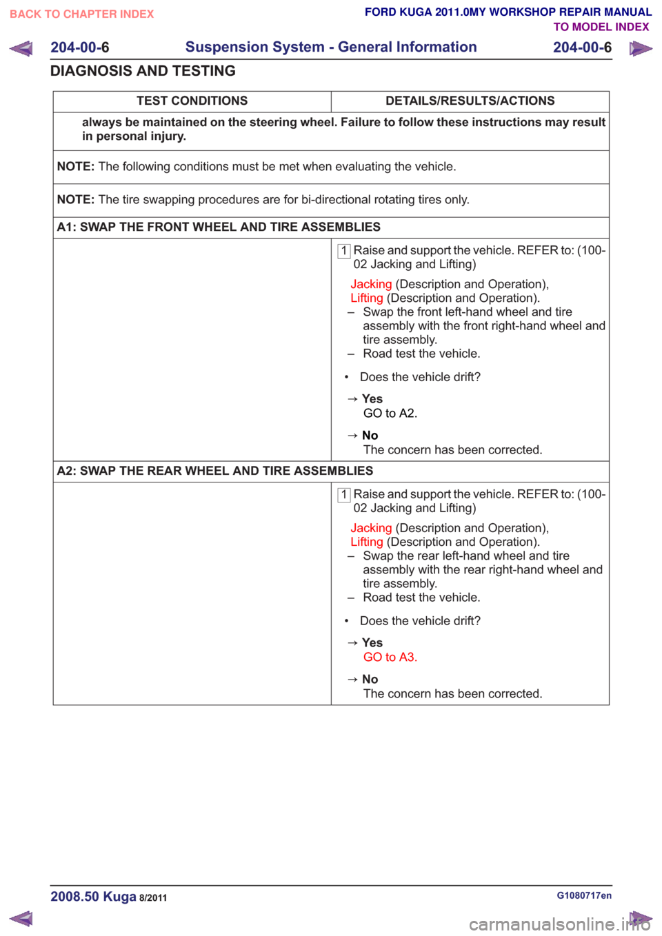
DETAILS/RESULTS/ACTIONS
TEST CONDITIONS
always be maintained on the steering wheel. Failure to follow these instructions may result
in personal injury.
NOTE: The following conditions must be met when evaluating the vehicle.
NOTE: The tire swapping procedures are for bi-directional rotating tires only.
A1: SWAP THE FRONT WHEEL AND TIRE ASSEMBLIES
1 Raise and support the vehicle. REFER to: (100-
02 Jacking and Lifting)
Jacking (Description and Operation),
Lifting (Description and Operation).
– Swap the front left-hand wheel and tire assembly with the front right-hand wheel and
tire assembly.
– Road test the vehicle.
• Does the vehicle drift?
zYe s GO to A2.
zNoThe concern has been corrected.
A2: SWAP THE REAR WHEEL AND TIRE ASSEMBLIES
1 Raise and support the vehicle. REFER to: (100-
02 Jacking and Lifting)
Jacking (Description and Operation),
Lifting (Description and Operation).
– Swap the rear left-hand wheel and tire assembly with the rear right-hand wheel and
tire assembly.
– Road test the vehicle.
• Does the vehicle drift?
zYe s GO to A3.
zNoThe concern has been corrected.
G1080717en2008.50 Kuga8/2011
204-00- 6
Suspension System - General Information
204-00- 6
DIAGNOSIS AND TESTING
TO MODEL INDEX
BACK TO CHAPTER INDEX
FORD KUGA 2011.0MY WORKSHOP REPAIR MANUAL
Page 1170 of 2057
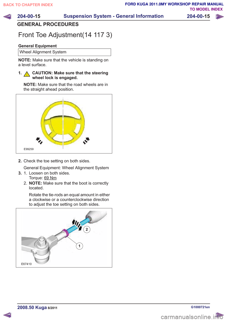
Front Toe Adjustment(14 117 3)
General EquipmentWheel Alignment System
NOTE: Make sure that the vehicle is standing on
a level surface.
1. CAUTION: Make sure that the steering wheel lock is engaged.
NOTE: Make sure that the road wheels are in
the straight ahead position.
E99259
2. Check the toe setting on both sides.
General Equipment: Wheel Alignment System
3. Loosen on both sides.
Torque: 69
Nm
1.
2.NOTE: Make sure that the boot is correctly
located.
Rotate the tie-rods an equal amount in either
a clockwise or a counterclockwise direction
to adjust the toe setting on both sides.
2
E67410
1
2
G1000721en2008.50 Kuga8/2011
204-00- 15
Suspension System - General Information
204-00- 15
GENERAL PROCEDURES
TO MODEL INDEX
BACK TO CHAPTER INDEX
FORD KUGA 2011.0MY WORKSHOP REPAIR MANUAL
Page 1236 of 2057
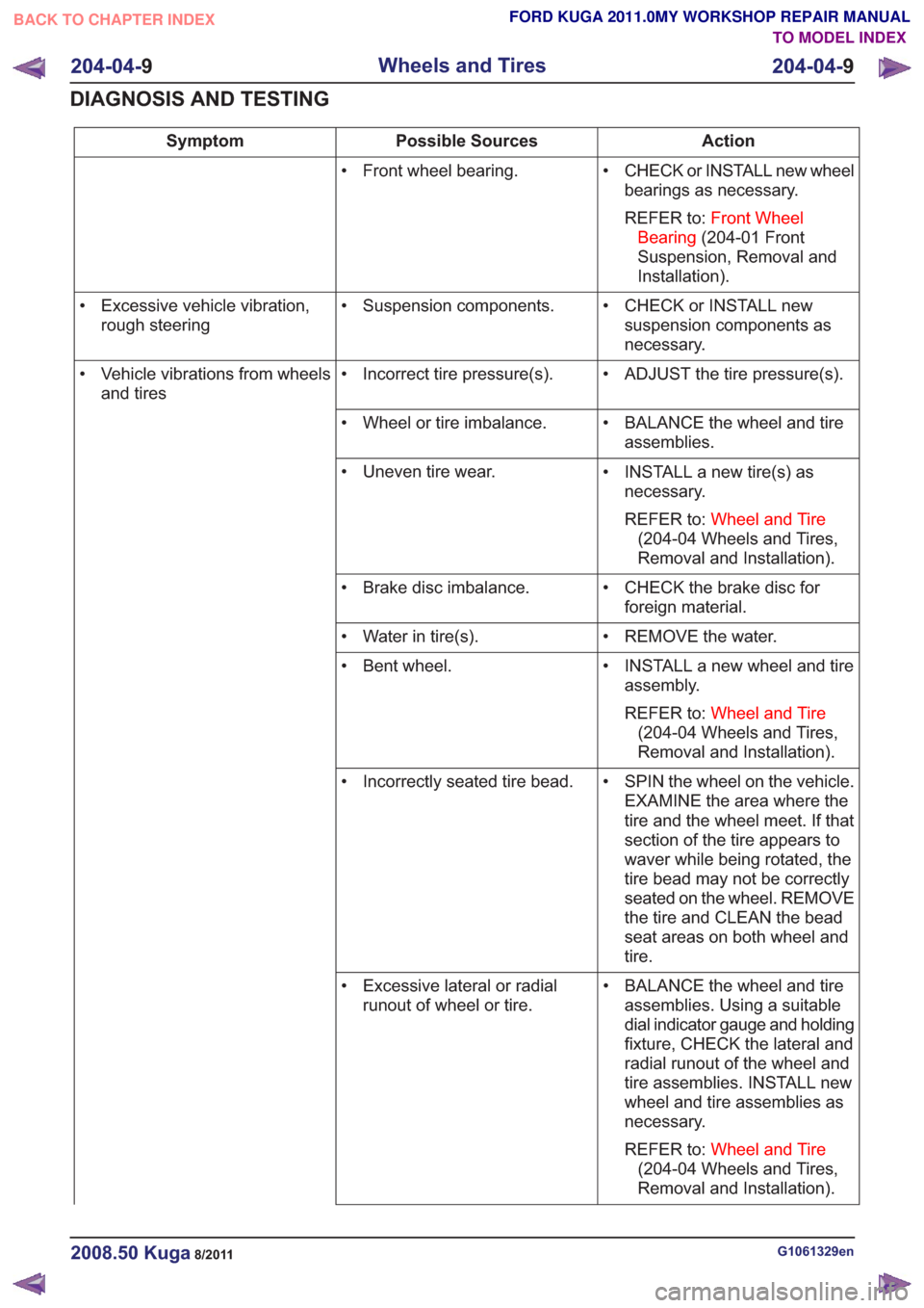
Action
Possible Sources
Symptom
• CHECK or INSTALL new wheelbearings as necessary.
REFER to: Front Wheel
Bearing (204-01 Front
Suspension, Removal and
Installation).
• Front wheel bearing.
• CHECK or INSTALL newsuspension components as
necessary.
• Suspension components.
• Excessive vehicle vibration,
rough steering
• ADJUST the tire pressure(s).
• Incorrect tire pressure(s).
• Vehicle vibrations from wheels
and tires
• BALANCE the wheel and tireassemblies.
• Wheel or tire imbalance.
• INSTALL a new tire(s) asnecessary.
REFER to: Wheel and Tire
(204-04 Wheels and Tires,
Removal and Installation).
• Uneven tire wear.
• CHECK the brake disc forforeign material.
• Brake disc imbalance.
• REMOVE the water.
• Water in tire(s).
• INSTALL a new wheel and tireassembly.
REFER to: Wheel and Tire
(204-04 Wheels and Tires,
Removal and Installation).
• Bent wheel.
• SPIN the wheel on the vehicle.EXAMINE the area where the
tire and the wheel meet. If that
section of the tire appears to
waver while being rotated, the
tire bead may not be correctly
seated on the wheel. REMOVE
the tire and CLEAN the bead
seat areas on both wheel and
tire.
• Incorrectly seated tire bead.
• BALANCE the wheel and tireassemblies. Using a suitable
dial indicator gauge and holding
fixture, CHECK the lateral and
radial runout of the wheel and
tire assemblies. INSTALL new
wheel and tire assemblies as
necessary.
REFER to: Wheel and Tire
(204-04 Wheels and Tires,
Removal and Installation).
• Excessive lateral or radial
runout of wheel or tire.
G1061329en2008.50 Kuga8/2011
204-04- 9
Wheels and Tires
204-04- 9
DIAGNOSIS AND TESTING
TO MODEL INDEX
BACK TO CHAPTER INDEX
FORD KUGA 2011.0MY WORKSHOP REPAIR MANUAL
Page 1298 of 2057
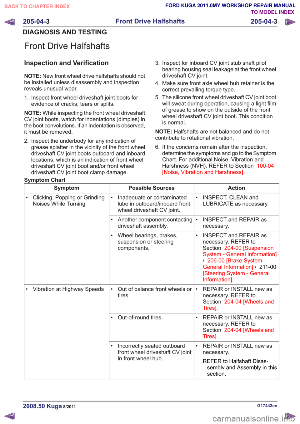
Front Drive Halfshafts
Inspection and Verification
NOTE:New front wheel drive halfshafts should not
be installed unless disassembly and inspection
reveals unusual wear.
1. Inspect front wheel driveshaft joint boots for evidence of cracks, tears or splits.
NOTE: While inspecting the front wheel driveshaft
CV joint boots, watch for indentations (dimples) in
the boot convolutions. If an indentation is observed,
it must be removed.
2. Inspect the underbody for any indication of grease splatter in the vicinity of the front wheel
driveshaft CV joint boots outboard and inboard
locations, which is an indication of front wheel
driveshaft CV joint boot and/or front wheel
driveshaft CV joint boot clamp damage. 3. Inspect for inboard CV joint stub shaft pilot
bearing housing seal leakage at the front wheel
driveshaft CV joint.
4. Make sure front axle wheel hub retainer is the correct prevailing torque type.
5. The silicone front wheel driveshaft CV joint boot will sweat during operation, causing a light film
of grease to show on the outside of the front
wheel driveshaft CV joint boot. This condition
is normal.
NOTE: Halfshafts are not balanced and do not
contribute to rotational vibration.
6. If the concerns remain after the inspection, determine the symptoms and go to the Symptom
Chart. For additional Noise, Vibration and
Harshness (NVH). REFER to Section 100-04
[Noise, Vibration and Harshness] .
Symptom Chart
Action
Possible Sources
Symptom
• INSPECT, CLEAN andLUBRICATE as necessary.
• Inadequate or contaminated
lube in outboard/inboard front
wheel driveshaft CV joint.
• Clicking, Popping or Grinding
Noises While Turning
• INSPECT and REPAIR asnecessary.
• Another component contacting
driveshaft assembly.
• INSPECT and REPAIR asnecessary. REFER to
Section 204-00 [Suspension
System - General Information]
/ 206-00 [Brake System -
General Information] /211-00
[Steering System - General
Information] .
• Wheel bearings, brakes,
suspension or steering
components.
• REPAIR or INSTALL new asnecessary. REFER to
Section 204-04 [Wheels and
Tires] .
• Out of balance front wheels or
tires.
• Vibration at Highway Speeds
• REPAIR or INSTALL new asnecessary. REFER to
Section 204-04 [Wheels and
Tires] .
• Out-of-round tires.
• REPAIR or INSTALL new asnecessary.
REFER to Halfshaft Disas-
semblv and Assembly in this
section.
• Incorrectly seated outboard
front wheel driveshaft CV joint
in front wheel hub.
G17442en2008.50 Kuga8/2011
205-04- 3
Front Drive Halfshafts
205-04- 3
DIAGNOSIS AND TESTING
TO MODEL INDEX
BACK TO CHAPTER INDEX
FORD KUGA 2011.0MY WORKSHOP REPAIR MANUAL