Page 1223 of 2057
6.
E99208
7.Torque: 115Nm
E101643
8.Refer to: Wheel Bearing and Wheel Hub (204-02
Rear Suspension, Removal and Installation).
9. Refer to: Spring(204-02 Rear Suspension,
Removal and Installation).
G1000235en2008.50 Kuga8/2011
204-02- 21
Rear Suspension
204-02- 21
REMOVAL AND INSTALLATION
TO MODEL INDEX
BACK TO CHAPTER INDEX
FORD KUGA 2011.0MY WORKSHOP REPAIR MANUAL
Page 1224 of 2057
Wheel Knuckle — LHD 4WD/RHD 4WD
Removal
1.Refer to: Spring(204-02 Rear Suspension,
Removal and Installation).
2. Refer to: Wheel Bearing and Wheel Hub (204-02
Rear Suspension, Removal and Installation).
3.
E101643
4.
E99208
5.
E93214
6.
E93206
Installation
1. Fabricate a spacer.
E69209
226
40
2. Torque: 120Nm1.
2.NOTE: Only tighten the bolt finger tight at
this stage.
E932621
2
G1000760en2008.50 Kuga8/2011
204-02- 22
Rear Suspension
204-02- 22
REMOVAL AND INSTALLATION
TO MODEL INDEX
BACK TO CHAPTER INDEX
FORD KUGA 2011.0MY WORKSHOP REPAIR MANUAL
Page 1226 of 2057
6.
E99208
7.Torque: 115Nm
E101643
8.Refer to: Wheel Bearing and Wheel Hub (204-02
Rear Suspension, Removal and Installation).
9. Refer to: Spring(204-02 Rear Suspension,
Removal and Installation).
G1000760en2008.50 Kuga8/2011
204-02- 24
Rear Suspension
204-02- 24
REMOVAL AND INSTALLATION
TO MODEL INDEX
BACK TO CHAPTER INDEX
FORD KUGA 2011.0MY WORKSHOP REPAIR MANUAL
Page 1227 of 2057
Spring(15 621 0)
Special Tool(s)204-167
Compressor, Coil Spring
14042
204-215
Adapter for 204-167
15111
Removal
NOTE:Removal steps in this procedure may
contain installation details. 1.
Refer to: Wheel and Tire (204-04 Wheels and
Tires, Removal and Installation).
2. CAUTION: Make sure that the ball joint ball does not rotate.
Torque: 70Nm
E98878
3.Install the Special Tool(s): 204-167, 204-215
E98877
1
2
204-167
204-215
Installation
1.To install, reverse the removal procedure.
G1000236en2008.50 Kuga8/2011
204-02- 25
Rear Suspension
204-02- 25
REMOVAL AND INSTALLATION
TO MODEL INDEX
BACK TO CHAPTER INDEX
FORD KUGA 2011.0MY WORKSHOP REPAIR MANUAL
Page 1235 of 2057

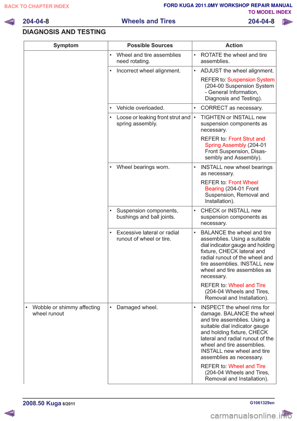
Action
Possible Sources
Symptom
• ROTATE the wheel and tireassemblies.
• Wheel and tire assemblies
need rotating.
• ADJUST the wheel alignment.REFER to: Suspension System
(204-00 Suspension System
- General Information,
Diagnosis and Testing).
• Incorrect wheel alignment.
• CORRECT as necessary.
• Vehicle overloaded.
• TIGHTEN or INSTALL newsuspension components as
necessary.
REFER to: Front Strut and
Spring Assembly (204-01
Front Suspension, Disas-
sembly and Assembly).
• Loose or leaking front strut and
spring assembly.
• INSTALL new wheel bearingsas necessary.
REFER to: Front Wheel
Bearing (204-01 Front
Suspension, Removal and
Installation).
• Wheel bearings worn.
• CHECK or INSTALL newsuspension components as
necessary.
• Suspension components,
bushings and ball joints.
• BALANCE the wheel and tireassemblies. Using a suitable
dial indicator gauge and holding
fixture, CHECK lateral and
radial runout of the wheel and
tire assemblies. INSTALL new
wheel and tire assemblies as
necessary.
REFER to: Wheel and Tire
(204-04 Wheels and Tires,
Removal and Installation).
• Excessive lateral or radial
runout of wheel or tire.
• INSPECT the wheel rims fordamage. BALANCE the wheel
and tire assemblies. Using a
suitable dial indicator gauge
and holding fixture, CHECK
lateral and radial runout of the
wheel and tire assemblies.
INSTALL new wheel and tire
assemblies as necessary.
REFER to: Wheel and Tire
(204-04 Wheels and Tires,
Removal and Installation).
• Damaged wheel.
• Wobble or shimmy affecting
wheel runout
G1061329en2008.50 Kuga8/2011
204-04- 8
Wheels and Tires
204-04- 8
DIAGNOSIS AND TESTING
TO MODEL INDEX
BACK TO CHAPTER INDEX
FORD KUGA 2011.0MY WORKSHOP REPAIR MANUAL
Page 1254 of 2057

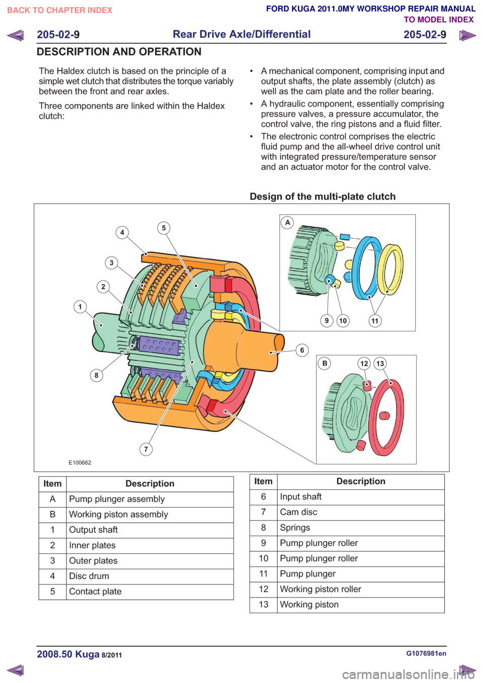
The Haldex clutch is based on the principle of a
simple wet clutch that distributes the torque variably
between the front and rear axles.
Three components are linked within the Haldex
clutch:• A mechanical component, comprising input and
output shafts, the plate assembly (clutch) as
well as the cam plate and the roller bearing.
• A hydraulic component, essentially comprising pressure valves, a pressure accumulator, the
control valve, the ring pistons and a fluid filter.
• The electronic control comprises the electric fluid pump and the all-wheel drive control unit
with integrated pressure/temperature sensor
and an actuator motor for the control valve.
Design of the multi-plate clutch
7
4
3
2
8
1
6
10911
13
A
B12
5
E100662
Description
Item
Pump plunger assembly
A
Working piston assembly
B
Output shaft
1
Inner plates
2
Outer plates
3
Disc drum
4
Contact plate
5Description
Item
Input shaft
6
Cam disc
7
Springs
8
Pump plunger roller
9
Pump plunger roller
10
Pump plunger
11
Working piston roller
12
Working piston
13
G1076981en2008.50 Kuga8/2011
205-02- 9
Rear Drive Axle/Differential
205-02- 9
DESCRIPTION AND OPERATION
TO MODEL INDEX
BACK TO CHAPTER INDEX
FORD KUGA 2011.0MY WORKSHOP REPAIR MANUAL
Page 1257 of 2057

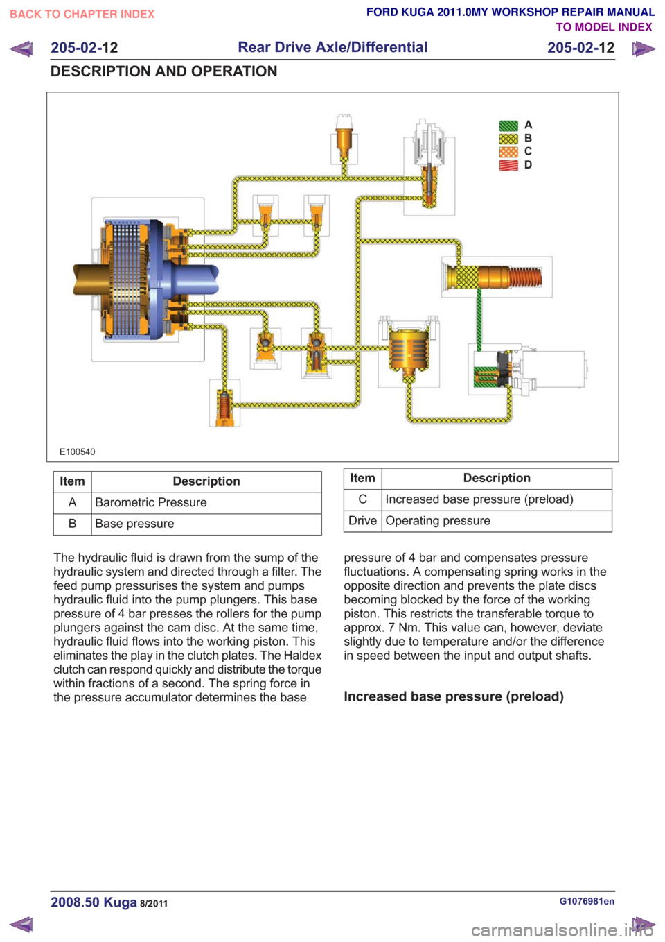
E100540
Description
Item
Barometric Pressure
A
Base pressure
BDescription
Item
Increased base pressure (preload)
C
Operating pressure
Drive
The hydraulic fluid is drawn from the sump of the
hydraulic system and directed through a filter. The
feed pump pressurises the system and pumps
hydraulic fluid into the pump plungers. This base
pressure of 4 bar presses the rollers for the pump
plungers against the cam disc. At the same time,
hydraulic fluid flows into the working piston. This
eliminates the play in the clutch plates. The Haldex
clutch can respond quickly and distribute the torque
within fractions of a second. The spring force in
the pressure accumulator determines the base pressure of 4 bar and compensates pressure
fluctuations. A compensating spring works in the
opposite direction and prevents the plate discs
becoming blocked by the force of the working
piston. This restricts the transferable torque to
approx. 7 Nm. This value can, however, deviate
slightly due to temperature and/or the difference
in speed between the input and output shafts.
Increased base pressure (preload)
G1076981en2008.50 Kuga8/2011
205-02-
12
Rear Drive Axle/Differential
205-02- 12
DESCRIPTION AND OPERATION
TO MODEL INDEX
BACK TO CHAPTER INDEX
FORD KUGA 2011.0MY WORKSHOP REPAIR MANUAL
Page 1299 of 2057

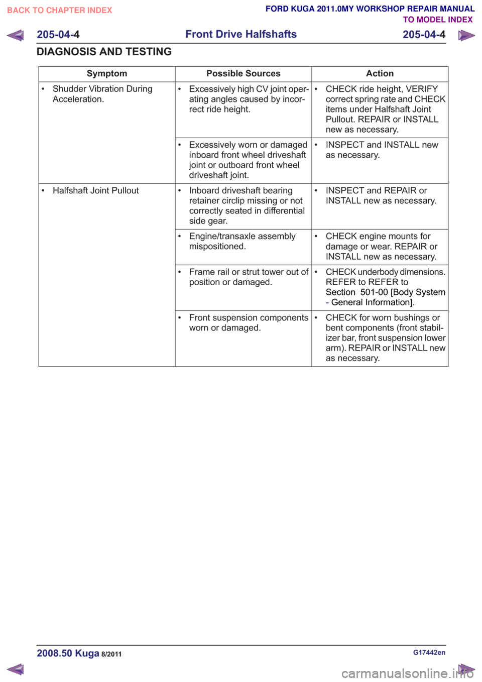
Action
Possible Sources
Symptom
• CHECK ride height, VERIFYcorrect spring rate and CHECK
items under Halfshaft Joint
Pullout. REPAIR or INSTALL
new as necessary.
• Excessively high CV joint oper-
ating angles caused by incor-
rect ride height.
• Shudder Vibration During
Acceleration.
• INSPECT and INSTALL newas necessary.
• Excessively worn or damaged
inboard front wheel driveshaft
joint or outboard front wheel
driveshaft joint.
• INSPECT and REPAIR orINSTALL new as necessary.
• Inboard driveshaft bearing
retainer circlip missing or not
correctly seated in differential
side gear.
• Halfshaft Joint Pullout
• CHECK engine mounts fordamage or wear. REPAIR or
INSTALL new as necessary.
• Engine/transaxle assembly
mispositioned.
• CHECK underbody dimensions.REFER to REFER to
Section 501-00 [Body System
-General Information] .
• Frame rail or strut tower out of
position or damaged.
• CHECK for worn bushings orbent components (front stabil-
izer bar, front suspension lower
arm). REPAIR or INSTALL new
as necessary.
• Front suspension components
worn or damaged.
G17442en2008.50 Kuga8/2011
205-04- 4
Front Drive Halfshafts
205-04- 4
DIAGNOSIS AND TESTING
TO MODEL INDEX
BACK TO CHAPTER INDEX
FORD KUGA 2011.0MY WORKSHOP REPAIR MANUAL